EP1745738A2 - Procédé et dispositif de mesure d'aberrations de fronts d'onde - Google Patents
Procédé et dispositif de mesure d'aberrations de fronts d'onde Download PDFInfo
- Publication number
- EP1745738A2 EP1745738A2 EP06076671A EP06076671A EP1745738A2 EP 1745738 A2 EP1745738 A2 EP 1745738A2 EP 06076671 A EP06076671 A EP 06076671A EP 06076671 A EP06076671 A EP 06076671A EP 1745738 A2 EP1745738 A2 EP 1745738A2
- Authority
- EP
- European Patent Office
- Prior art keywords
- wavefront
- aberrations
- portions
- eye
- imaging device
- Prior art date
- Legal status (The legal status is an assumption and is not a legal conclusion. Google has not performed a legal analysis and makes no representation as to the accuracy of the status listed.)
- Withdrawn
Links
Images


Classifications
-
- A—HUMAN NECESSITIES
- A61—MEDICAL OR VETERINARY SCIENCE; HYGIENE
- A61B—DIAGNOSIS; SURGERY; IDENTIFICATION
- A61B3/00—Apparatus for testing the eyes; Instruments for examining the eyes
- A61B3/10—Objective types, i.e. instruments for examining the eyes independent of the patients' perceptions or reactions
- A61B3/103—Objective types, i.e. instruments for examining the eyes independent of the patients' perceptions or reactions for determining refraction, e.g. refractometers, skiascopes
-
- G—PHYSICS
- G01—MEASURING; TESTING
- G01J—MEASUREMENT OF INTENSITY, VELOCITY, SPECTRAL CONTENT, POLARISATION, PHASE OR PULSE CHARACTERISTICS OF INFRARED, VISIBLE OR ULTRAVIOLET LIGHT; COLORIMETRY; RADIATION PYROMETRY
- G01J9/00—Measuring optical phase difference; Determining degree of coherence; Measuring optical wavelength
-
- A—HUMAN NECESSITIES
- A61—MEDICAL OR VETERINARY SCIENCE; HYGIENE
- A61B—DIAGNOSIS; SURGERY; IDENTIFICATION
- A61B3/00—Apparatus for testing the eyes; Instruments for examining the eyes
- A61B3/10—Objective types, i.e. instruments for examining the eyes independent of the patients' perceptions or reactions
- A61B3/1015—Objective types, i.e. instruments for examining the eyes independent of the patients' perceptions or reactions for wavefront analysis
-
- G—PHYSICS
- G01—MEASURING; TESTING
- G01J—MEASUREMENT OF INTENSITY, VELOCITY, SPECTRAL CONTENT, POLARISATION, PHASE OR PULSE CHARACTERISTICS OF INFRARED, VISIBLE OR ULTRAVIOLET LIGHT; COLORIMETRY; RADIATION PYROMETRY
- G01J1/00—Photometry, e.g. photographic exposure meter
- G01J1/02—Details
- G01J1/04—Optical or mechanical part supplementary adjustable parts
- G01J1/0407—Optical elements not provided otherwise, e.g. manifolds, windows, holograms, gratings
- G01J1/0414—Optical elements not provided otherwise, e.g. manifolds, windows, holograms, gratings using plane or convex mirrors, parallel phase plates, or plane beam-splitters
Definitions
- the present invention relates generally to optical instruments and, more particularly, to a method and apparatus for measuring wavefront aberrations.
- the present invention is particularly useful, but not exclusively so, for measuring the optical wavefront in ophthalmic applications, e.g., measurement of aberrations of the eye, in corrective devices such as lenses (e.g., contact, spectacle, and intraocular), and for evaluating the ocular aberrations before during and after refractive surgery to improve vision.
- the human eye is an optical system which employs a lens to focus light rays representing images onto the retina within the eye.
- the sharpness of the images produced on the retina is a factor in determining the visual acuity of the eye.
- Imperfections within the lens and other components and material within the eye may cause the light rays to deviate from a desired path. These deviations, referred to as aberrations, result in blurred images and decreased visual acuity.
- a method and apparatus for measuring aberrations is desirable to aid in the correction of such problems.
- One method of detecting aberrations introduced by an eye involves determining the aberrations of light rays exiting from within the eye.
- a beam of light directed into the eye as a point on the retina is reflected or scattered back out of the eye as a wavefront.
- the wavefront represents the direction of light rays exiting from the eye.
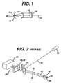
- FIG. 1 is a schematic view of a wavefront 10 generated by reflecting a laser beam 12 off of the retina 20 of an eye 16.
- the laser beam 12 focuses to a small spot 14 on the retina 20.
- the retina 20, acting as a diffuse reflector, reflects the laser beam 12, resulting in a point source wavefront 10.
- the wavefront 10 from a point source leaving a perfect eye would be represented by a spherical or planar wavefront 22.
- aberrations introduced by the eye 16 as the wavefront passes out of the eye result in an imperfect wavefront, as illustrated by the wavefront 10.
- the wavefront 10 represents aberrations which lead to defocus, astigmatism, spherical aberrations, coma, and other irregularities. Measuring and correcting these aberrations allow the eye 16 to approach its full potential, i.e., the limits of visual resolution.
- FIG. 2 is an illustration of a prior art apparatus for measuring the wavefront 10 as illustrated in FIG. 1.
- corrective lens can be produced and/or corrective procedures performed to improve vision.
- a laser 22 generates the laser beam 12 which is routed to the eye 16 by a beam splitter 25.
- the laser beam 12 forms a spot 14 on the retina 20 of the eye 16.
- the retina reflects the light from the spot 14 to create a point source wavefront 10 which becomes aberrated as it passes through the lens and other components and material within the eye 16.
- the wavefront 10 passes through the beam splitter 25 toward a wavefront sensor 26.
- the apparatus described in Figure 2 is commonly described as single-pass wavefront measurement system.
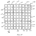
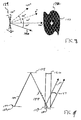
- Typical prior art wavefront sensors 26 include either an aberroscope 30 and an imaging plane 28, as illustrated in FIG. 3, or a Hartmann-Shack sensor 40 and an imaging plane 28, as illustrated in FIG. 4.
- the wavefront sensor 26 samples the wavefront 10 by passing the wavefront 10 through the aberroscope 30 or the Hartmann-Shack sensor 40, resulting in the wavefront 10 producing an array of spots on an imaging plane 28.
- the imaging plane 28 is a charge coupled device (CCD) camera.
- Each spot on the imaging plane 28 represents a portion of the wavefront 10, with smaller portions enabling the aberrations to be determined with greater precision.
- Foldover may result from a grid size 32 or lenslet sub-aperture spacing 42 which is too small, a high degree of aberration, or a combination of these conditions.
- the grid size 32 or lenslet sub-aperture spacing 42 must be balanced to achieve good spatial resolution while enabling the measurement of large aberrations. Accordingly, the ability to measure a high degree of aberration comes at the expense of spatial resolution and vice versa.
- the present invention discloses an apparatus and method for determining the aberrations of a wavefront with a high degree of accuracy.
- the apparatus includes a plurality of mirrors for reflecting selected portions of the wavefront, an imaging device for capturing information related to the selected portions, and a processor for controlling the plurality of mirrors and interpreting the captured information to compute the aberrations.
- the method includes reflecting selected portions of a wavefront onto an imaging device, capturing information related to the selected portions, and processing the captured information to derive the aberrations.
- the apparatus and method of the present invention are capable of measuring a wide range of aberrations with a high degree of spatial resolution.
- the wavefront originates as a point source within a focusing optical system (e.g. the eye).
- the point source is generated by directing a beam of radiation (e.g., a laser) through the focusing optical system and scattering or reflecting the beam.
- a beam splitter disposed in the path of the laser beam directs the laser beam through the focusing optical system.
- the focusing optical system has an interior portion functioning as a diffuse reflector for reflecting or scattering the beam.
- the wavefront resulting from the point source passes through the focusing optical system and the beam splitter to the wavefront sensor of the present invention.
- the wavefront sensor measures distortions of the wavefront as an estimate of aberrations introduced by the focusing optical system. Aberrations are then computed by a processor coupled to the wavefront sensor.
- FIG. 5 Illustrated in FIG. 5 is a preferred embodiment of a wavefront measuring device 100 in accordance with the present invention.
- a radiation source 110 generates a beam 112.
- the beam 112 passes through an optional beam splitter 114 unaltered.
- Another beam splitter 116 redirects the beam 112 toward an optical system 115, e.g., an eye 118.
- the beam 112 enters the eye 118 through the cornea 120 where it is reflected by the retina 124 to produce a point source image wavefront 126 that travels back out of the eye 118.
- the wavefront 126 is affected by defects within the eye 118 which cause the aberrations.
- the affected wavefront 126 passes through the beam splitter 116 toward a reflection device 128.
- Individual mirror regions 130 within the reflection device 128 selectively reflect portions of the wavefront 126 toward an imaging device 132, via a redirecting mirror 134, which captures information related to the wavefront 126.
- a processor 136 is used to control the reflection device 130 and to process the captured information.
- the radiation source 110 is a device capable of generating a focused beam of photons, and is preferably a laser.
- Alternative radiation sources 110 include a laser diode, super-luminescent diode, or essentially any suitable radiation device. Additionally, the radiation source 110 may include a spacial filter for correcting noise associated with the radiation source 110.
- the optional beam splitter 114 is a device capable of selectively passing and directing beams within the wavefront measuring device 100.
- the optional beam splitter 114 is configured to pass light generated by the radiation source 110 and to reflect light from the fixation target 117. This configuration allows light from the fixation target 117 to be placed in the same path as light from the radiation source 110 that is heading toward the eye 118.
- the fixation target 117 is an optional component which provides a focusing point for the person whose eye 118 is being scanned, thereby controlling eye movements and accommodation (focusing).
- the optional beam splitter 114 can be removed if the fixation target 117 is not used.
- the optional beam splitter 114 is a polarizing beam splitter which selectively passes or reflects light based on the polarization of the light.
- the other beam splitter 116 is also capable of selectively passing and directing beams.
- the beam splitter 116 is configured to reflect the beam 112 and light from the fixation target 117 toward the optical system 115, e.g., the eye 118, and to pass the light projecting from the optical system 115 unaltered.
- the beam splitter 116 is also a polarizing beam splitter as discussed above.
- the illustrated optical system 115 is the eye 118.
- the optical system may include a reflective surface and a contact lens or eyeglass, an eye and a contact lens or eyeglass, a telescope, a microscope, or other type of optical system.
- the beam 112 from the radiation source 110 is kept much smaller than the diffraction limited pupil aperture (approx. 2 mm) in order to form a spot 122 on the retina 124.
- a focusing lens may also be used in the path of the beam 112 to account for defocus and/or astigmatism of the eye.
- the retina 124 acting as a diffuse reflector, effectively becomes the source for light leaving the eye 118, thereby creating the wavefront 126.
- One or more optical devices are positioned between the eye 118 and the reflection device 128.
- the lenses 125 transfer the point source image wavefront 126 between the eye 118 and the reflection device 128 such that the propagation directions of the waves which make up the wavefront 126 are preserved as they are passed from the eye 118 to the reflection device 128.
- Optical devices such as the lenses 125 used in the present invention are well known to those in the art.
- the reflection device 128 has a plurality of mirrors 129 which form or can be grouped to form mirror regions 130 (see FIG. 5 and 5A).
- Each mirror region 130 is capable of reflecting a portion of the wavefront 126 for measurement of that portion independent of the other portions (see FIG 5B).
- each mirror region 130 may be oriented in at least two positions. In a first position 133 (FIG. 5B), a mirror region 130 will reflect a portion 140 of the wavefront 126 incident on the mirror region 130 in a direction to be received by the imaging device 132 and, in a second position 135, the mirror regions 130 will reflect the portions of the wavefront 126 in a direction away from the imaging device 132.
- Each mirror region 130 may be formed of a single mirror 129, or multiple mirrors 129 which are preferably adjacent to one another as illustrated in FIG. 5A.
- each mirror region 130 may include a single mirror 129, an array of 3 mirrors by 3 mirrors as illustrated in FIG. 5A, an array of 100 mirrors by 100 mirrors, or any other suitable grouping. While the present embodiment contemplates that each mirror region 130 would have the same configuration of mirrors, such in not believed necessary.
- FIG. 6 illustrates the reflection of a portion 140 of the wavefront 126 by a mirror region 130 within a reflection device 128 toward an imaging device 132 to determine an aberration.
- the mirror region 130 has a single mirror 129.
- a mirror 129 such as mirror 131 is in the first position 133 (see FIG. 5B)
- the wavefront portion 140 is directed toward an imaging plane 142 of the imaging device 132 as a reflected wavefront portion 144.
- the other mirrors 129 such as the mirror 137 in the second position 135 (see FIG. 5B) reflect the portion of the wavefront 126 incident thereon away from imaging plane 142, such as to area 139.
- each of the mirrors 129 or group of mirrors 130 are in turn positioned to reflect the respective portion of the wavefront incident thereon towards the imaging device 132, and then repositioned to reflect away as another mirror 129 is positioned to reflect towards the imaging device 132.
- a mirror region 130 has more than one mirror 129, then preferably, all mirrors 129 of each mirror region 130 are positioned as a unit.
- Aberrations within the wavefront portion 140 displace the reflected wavefront portion 144 from an aberration free path 146 by an amount proportional to the local slope of the wavefront portion 140 corresponding to the mirror 131.
- the propagation direction of the wavefront portion 140 can be computed using a known method such as an inverse tangential function, i.e., the ratio of the length of the side opposite the angle of the wavefront portion 140 to the length of the side adjacent to the angle.
- the aberrations of the wavefront portion 140 can then be calculated using known methods.
- each mirror region 130 is individually oriented to direct a corresponding portion of the wavefront 126 toward the imaging device 132 where information related to that portion is captured by the imaging device 132.
- more than one of the mirror regions 130 may be oriented to direct respective portions of the wavefront 126 toward the imaging device 132 substantially simultaneously. If more than one of the mirror regions 130 direct simultaneously respective portions of the wavefront 126 toward the imaging device 132, such mirror regions 130 should be separated by another region of mirrors which reflect away from the imaging device 132 to prevent foldover between the imaged regions. For example, referring to FIG.
- the two mirror regions 130A and 130C will be separated by one or more mirror regions 130 such as a third mirror region 130B which will be oriented to reflect a respective portion of the wavefront 126 away from the imaging device 132.
- the speed required to capture all of the wavefront 126 and the spatial resolution of the system can be adjusted.
- DMD TM Digital Micromirror Device
- DMD TM Digital Micromirror Device
- U.S. Patent No. 5,096,279 to Hombeck et al. entitled “Spatial Light Modulator and Method”
- U.S. Patent No. 4,954,789 to Sampsell entitled “Spatial Light Modulator,” both of which are incorporated herein by reference.
- FIG. 7 depicts a portion of a Digital Micromirror Device TM (DMDTM) 150.
- DMDTM Digital Micromirror Device
- a DMDTM includes an array of hundreds or thousands of tiny tiltable mirrors 129, each of which is capable of reflecting a portion of the wavefront 126.
- FIG. 7 depicts two individual mirrors 129 within the DMDTM 150.
- each mirror 129 is attached to one or more hinges 152 mounted on support posts, and spaced by means of a fluidic (air or liquid) gap over underlying control circuitry on a CMOS substrate 154.
- the control circuitry provides electrostatic forces, which cause each mirror 129 to selectively tilt.
- data is loaded to memory cells of the DMDTM 150 and, in accordance with this data, individual mirrors 129 are tilted so as to either reflect light towards or away from the imaging device 132 via the redirecting mirror 134 as seen in FIG. 5.
- Suitable DMDTM devices include SXGA and SVGA DMDTM devices available from Texas Instruments.
- FIG. 8 depicts in detail the reflection of the wavefront portion 140 (FIG. 6) by a mirror 129 of a DMDTM.
- the individual mirror 129 has three positions (i.e., -10°, 0°, +10°).
- the wavefront portion 140 In the +10° position, representing the first position 133 of FIG. 5B, the wavefront portion 140 is directed toward the imaging plane 142.
- the imaging plane 142 includes a plurality of cells 143 capable of detecting energy from the wavefront portion 140.
- each mirror of a DMDTM has three positions, only two are needed in the present invention.
- the wavefront portions 140 are directed toward the imaging device 132 via a redirecting mirror 134.
- the redirecting mirror 134 is optically positioned (not necessarily physically positioned) between the reflection device 128 and the imaging device 132 to reflect the wavefront portions 140 from the mirror regions 130 to the imaging device 132. This facilitates the placement of the imaging device 132 in relation to the plurality of mirrors 128.
- the wavefront portions could pass directly from the reflection device 128 to the imaging device 132, thereby eliminating the need for the redirecting mirror 134.
- FIG. 9 depicts in detail the operation of redirecting mirror 134 as seen in FIG. 5.
- the reflection of a wavefront portion 144 is isolated from the entire wavefront 126 by the mirror region 130 within the reflection device 128.
- the reflection of the wavefront portion 144 is reflected off of a redirecting mirror 134 onto the imaging plane 142 of the imaging device 132.
- the unmeasured portions 147 of the wavefront 126 are directed away from the imaging plane 142.
- the redirecting mirror 134 facilitates the placement of the imaging device 132 in relation to the reflection device 128 by adding flexibility.
- the flexibility is due to the ability to position the imaging device 132 in a location other than in the direct line of sight the reflection device 128.
- the imaging device 132 is capable of precisely detecting the location of energy incident to an imaging plane 133.
- the imaging device 132 is a charge coupled device (CCD) camera.
- a charge coupled camera is a device capable of converting energy incident to an imaging plane 133 into a digital representation.
- Charge coupled devices are well known and a suitable device for use with the present invention would be readily apparent to those skilled in the art.
- the processor 136 controls the orientation of the mirror regions 130.
- the processor 136 receives information from the imaging device 132 and analyzes the information to compute the aberrations.
- the information may be stored in a storage register prior to processing by processor 136 or may be processed immediately.
- the processor 136 orients the individual mirror regions 130 (all the mirrors 129 of the mirror region 130) to reflect towards the imaging device 128 at different times for computing the aberrations of the wavefront 126.
- the processor 136 substantially simultaneously orients two or more mirror regions toward the imaging device 132 to compute the aberrations of the wavefront 126.
- the individual mirror regions 130 are separated by a buffer mirror region reflecting away from the imaging device 132 to prevent foldover between portions of the wavefront 126 corresponding to the individual mirror regions 130 as previously discussed. It is apparent to those skilled in the art that the control of the plurality of mirrors 128, the receipt of information from the imaging device 132, and the processing of information may be performed by a single processor or divided among a plurality of processors.
- the aberration correction device 138 is coupled to the processor 136.
- information calculated by the processor 136 may be stored on a hard drive, diskette, server, compact disc, digital versatile disc, or essentially any device capable of storing information.
- the stored information is then passed to an aberration correction device 138.
- the aberration correction device 138 includes a known lens grinder, contact lens manufacturing system, surgical laser system, or other optical system correction device.
- a laser can be optically positioned relative to the beam splitter 116 to direct a laser cutting beam toward the cornea 120 of the eye 118, in a manner well known in the art, for the purpose of performing ophthalmic surgery.
- the present invention has been described in terms of measuring wavefront aberrations introduced by a human eye.
- the present invention can be used to measure aberrations created by other optical systems, e.g. eyeglasses, telescopes, binoculars, monoculars, contact lenses, non-human eyes, or combination of these systems.
Landscapes
- Physics & Mathematics (AREA)
- Health & Medical Sciences (AREA)
- Life Sciences & Earth Sciences (AREA)
- Spectroscopy & Molecular Physics (AREA)
- General Physics & Mathematics (AREA)
- Medical Informatics (AREA)
- General Health & Medical Sciences (AREA)
- Heart & Thoracic Surgery (AREA)
- Engineering & Computer Science (AREA)
- Molecular Biology (AREA)
- Surgery (AREA)
- Animal Behavior & Ethology (AREA)
- Biomedical Technology (AREA)
- Public Health (AREA)
- Veterinary Medicine (AREA)
- Ophthalmology & Optometry (AREA)
- Biophysics (AREA)
- Eye Examination Apparatus (AREA)
- Testing Of Optical Devices Or Fibers (AREA)
Applications Claiming Priority (2)
| Application Number | Priority Date | Filing Date | Title |
|---|---|---|---|
| US09/677,191 US6616279B1 (en) | 2000-10-02 | 2000-10-02 | Method and apparatus for measuring wavefront aberrations |
| EP01975284A EP1326525B1 (fr) | 2000-10-02 | 2001-09-21 | Appareil de mesure des aberrations de front d'ondes |
Related Parent Applications (1)
| Application Number | Title | Priority Date | Filing Date |
|---|---|---|---|
| EP01975284A Division EP1326525B1 (fr) | 2000-10-02 | 2001-09-21 | Appareil de mesure des aberrations de front d'ondes |
Publications (2)
| Publication Number | Publication Date |
|---|---|
| EP1745738A2 true EP1745738A2 (fr) | 2007-01-24 |
| EP1745738A3 EP1745738A3 (fr) | 2007-08-29 |
Family
ID=24717687
Family Applications (2)
| Application Number | Title | Priority Date | Filing Date |
|---|---|---|---|
| EP01975284A Expired - Lifetime EP1326525B1 (fr) | 2000-10-02 | 2001-09-21 | Appareil de mesure des aberrations de front d'ondes |
| EP06076671A Withdrawn EP1745738A3 (fr) | 2000-10-02 | 2001-09-21 | Procédé et dispositif de mesure d'aberrations de fronts d'onde |
Family Applications Before (1)
| Application Number | Title | Priority Date | Filing Date |
|---|---|---|---|
| EP01975284A Expired - Lifetime EP1326525B1 (fr) | 2000-10-02 | 2001-09-21 | Appareil de mesure des aberrations de front d'ondes |
Country Status (11)
| Country | Link |
|---|---|
| US (2) | US6616279B1 (fr) |
| EP (2) | EP1326525B1 (fr) |
| JP (1) | JP2004516457A (fr) |
| KR (1) | KR20030065486A (fr) |
| CN (2) | CN1757374A (fr) |
| AU (2) | AU9462301A (fr) |
| BR (1) | BRPI0114406B8 (fr) |
| CA (2) | CA2424169C (fr) |
| DE (1) | DE60130231D1 (fr) |
| TW (1) | TW529927B (fr) |
| WO (1) | WO2002028272A1 (fr) |
Cited By (2)
| Publication number | Priority date | Publication date | Assignee | Title |
|---|---|---|---|---|
| WO2014074598A1 (fr) * | 2012-11-07 | 2014-05-15 | Clarity Medical Systems, Inc. | Appareil et procédé pour le fonctionnement d'un capteur de fronts d'onde séquentiel en temps réel à large plage de dioptries |
| US9585553B2 (en) | 2006-01-20 | 2017-03-07 | Clarity Medical Systems Inc. | Apparatus and method for operating a real time large diopter range sequential wavefront sensor |
Families Citing this family (72)
| Publication number | Priority date | Publication date | Assignee | Title |
|---|---|---|---|---|
| US6619799B1 (en) | 1999-07-02 | 2003-09-16 | E-Vision, Llc | Optical lens system with electro-active lens having alterably different focal lengths |
| US6871951B2 (en) | 2000-06-23 | 2005-03-29 | E-Vision, Llc | Electro-optic lens with integrated components |
| US6857741B2 (en) | 2002-01-16 | 2005-02-22 | E-Vision, Llc | Electro-active multi-focal spectacle lens |
| US6986579B2 (en) * | 1999-07-02 | 2006-01-17 | E-Vision, Llc | Method of manufacturing an electro-active lens |
| US7023594B2 (en) | 2000-06-23 | 2006-04-04 | E-Vision, Llc | Electro-optic lens with integrated components |
| US7775660B2 (en) | 1999-07-02 | 2010-08-17 | E-Vision Llc | Electro-active ophthalmic lens having an optical power blending region |
| US6851805B2 (en) * | 1999-07-02 | 2005-02-08 | E-Vision, Llc | Stabilized electro-active contact lens |
| US7290876B2 (en) | 1999-07-02 | 2007-11-06 | E-Vision, Llc | Method and system for electro-active spectacle lens design |
| US7988286B2 (en) | 1999-07-02 | 2011-08-02 | E-Vision Llc | Static progressive surface region in optical communication with a dynamic optic |
| US7604349B2 (en) | 1999-07-02 | 2009-10-20 | E-Vision, Llc | Static progressive surface region in optical communication with a dynamic optic |
| US7404636B2 (en) | 1999-07-02 | 2008-07-29 | E-Vision, Llc | Electro-active spectacle employing modal liquid crystal lenses |
| US7290875B2 (en) | 2004-11-02 | 2007-11-06 | Blum Ronald D | Electro-active spectacles and method of fabricating same |
| US7264354B2 (en) * | 1999-07-02 | 2007-09-04 | E-Vision, Llc | Method and apparatus for correcting vision using an electro-active phoropter |
| US6685317B2 (en) | 2000-06-13 | 2004-02-03 | Massie Research Laboratories, Inc. | Digital eye camera |
| DE10290005B4 (de) * | 2001-01-03 | 2016-03-10 | Imedos Systems Ug (Haftungsbeschränkt) | Vorrichtung und Verfahren zur Bildgebung, Stimulierung, Messung und Therapie insbesondere am Auge |
| EP1433020A1 (fr) * | 2001-10-05 | 2004-06-30 | E-Vision, LLC | Lentille electro-active hybride |
| US6712466B2 (en) | 2001-10-25 | 2004-03-30 | Ophthonix, Inc. | Eyeglass manufacturing method using variable index layer |
| US7034949B2 (en) | 2001-12-10 | 2006-04-25 | Ophthonix, Inc. | Systems and methods for wavefront measurement |
| US6781681B2 (en) | 2001-12-10 | 2004-08-24 | Ophthonix, Inc. | System and method for wavefront measurement |
| US7249851B2 (en) * | 2001-12-11 | 2007-07-31 | Kabushiki Kaisha Topcon | Eye characteristic measuring apparatus |
| US6761454B2 (en) | 2002-02-13 | 2004-07-13 | Ophthonix, Inc. | Apparatus and method for determining objective refraction using wavefront sensing |
| US20050174535A1 (en) | 2003-02-13 | 2005-08-11 | Lai Shui T. | Apparatus and method for determining subjective responses using objective characterization of vision based on wavefront sensing |
| AU2003283058B2 (en) * | 2002-11-20 | 2009-11-05 | Clearmark Technologies Pty Ltd | A corneal topographer |
| AU2002952772A0 (en) * | 2002-11-20 | 2002-12-05 | Clearmark Technologies Pty Ltd | A corneal topographer |
| AR045370A1 (es) | 2003-08-15 | 2005-10-26 | E Vision Llc | Sistema de lente electro-activo |
| US8915588B2 (en) | 2004-11-02 | 2014-12-23 | E-Vision Smart Optics, Inc. | Eyewear including a heads up display |
| US8778022B2 (en) | 2004-11-02 | 2014-07-15 | E-Vision Smart Optics Inc. | Electro-active intraocular lenses |
| MX2007005198A (es) | 2004-11-02 | 2007-06-20 | E Vision Llc | Anteojos electro-activos y metodos para fabricarlos. |
| US9801709B2 (en) | 2004-11-02 | 2017-10-31 | E-Vision Smart Optics, Inc. | Electro-active intraocular lenses |
| DE102004063838A1 (de) * | 2004-12-23 | 2006-07-06 | Seereal Technologies Gmbh | Verfahren und Einrichtung zum Berechnen computer generierter Videohologramme |
| US7452074B2 (en) | 2005-09-27 | 2008-11-18 | Transitions Optical, Inc. | Optical elements and method of making the same using liquid crystal materials |
| US8356900B2 (en) | 2006-01-20 | 2013-01-22 | Clarity Medical Systems, Inc. | Large diopter range real time sequential wavefront sensor |
| US8100530B2 (en) * | 2006-01-20 | 2012-01-24 | Clarity Medical Systems, Inc. | Optimizing vision correction procedures |
| US8820929B2 (en) | 2006-01-20 | 2014-09-02 | Clarity Medical Systems, Inc. | Real-time measurement/display/record/playback of wavefront data for use in vision correction procedures |
| US9101292B2 (en) | 2006-01-20 | 2015-08-11 | Clarity Medical Systems, Inc. | Apparatus and method for operating a real time large dipoter range sequential wavefront sensor |
| US7445335B2 (en) * | 2006-01-20 | 2008-11-04 | Clarity Medical Systems, Inc. | Sequential wavefront sensor |
| US8777413B2 (en) | 2006-01-20 | 2014-07-15 | Clarity Medical Systems, Inc. | Ophthalmic wavefront sensor operating in parallel sampling and lock-in detection mode |
| US20080273166A1 (en) | 2007-05-04 | 2008-11-06 | William Kokonaski | Electronic eyeglass frame |
| US7656509B2 (en) | 2006-05-24 | 2010-02-02 | Pixeloptics, Inc. | Optical rangefinder for an electro-active lens |
| JP2009541793A (ja) | 2006-06-23 | 2009-11-26 | ピクセルオプティクス, インコーポレイテッド | 電気活性眼鏡レンズ用の電子アダプタ |
| GB0616974D0 (en) | 2006-08-29 | 2006-10-04 | Univ Heriot Watt | Optical characteristic mapping instrument |
| AR064985A1 (es) | 2007-01-22 | 2009-05-06 | E Vision Llc | Lente electroactivo flexible |
| MX2009008829A (es) | 2007-02-23 | 2011-10-28 | Pixeloptics Inc | Apertura dinamica oftalmica. |
| US7883207B2 (en) | 2007-12-14 | 2011-02-08 | Pixeloptics, Inc. | Refractive-diffractive multifocal lens |
| CA2679977A1 (fr) | 2007-03-07 | 2008-09-18 | Pixeloptics, Inc. | Lentille multifocale possedant une region de puissance optique progressive et une discontinuite |
| US20080273169A1 (en) | 2007-03-29 | 2008-11-06 | Blum Ronald D | Multifocal Lens Having a Progressive Optical Power Region and a Discontinuity |
| US10613355B2 (en) | 2007-05-04 | 2020-04-07 | E-Vision, Llc | Moisture-resistant eye wear |
| US12572035B2 (en) | 2007-05-04 | 2026-03-10 | E-Vision Optics, Llc | Moisture-resistant eye wear |
| US11061252B2 (en) | 2007-05-04 | 2021-07-13 | E-Vision, Llc | Hinge for electronic spectacles |
| US8317321B2 (en) | 2007-07-03 | 2012-11-27 | Pixeloptics, Inc. | Multifocal lens with a diffractive optical power region |
| BRPI0908992A2 (pt) | 2008-03-18 | 2015-11-24 | Pixeloptics Inc | dispositivo ótico eletro-ativo avançado |
| US8154804B2 (en) | 2008-03-25 | 2012-04-10 | E-Vision Smart Optics, Inc. | Electro-optic lenses for correction of higher order aberrations |
| RU2566919C2 (ru) | 2010-02-12 | 2015-10-27 | Джонсон Энд Джонсон Вижн Кэа, Инк. | Устройство и способ получения клинических офтальмологических оптических аберраций высшего порядка |
| CN102844651B (zh) * | 2010-04-05 | 2015-07-01 | 株式会社尼康 | 波前像差测定装置 |
| US12436411B2 (en) | 2010-07-02 | 2025-10-07 | E-Vision Optics, Llc | Moisture-resistant eye wear |
| US12510773B2 (en) | 2011-02-11 | 2025-12-30 | E-Vision Optics, Llc | Moisture-resistant eye wear |
| US20130063699A1 (en) * | 2011-09-09 | 2013-03-14 | Welch Allyn, Inc. | Ocular Error Detection |
| DE102011113953A1 (de) * | 2011-09-16 | 2013-03-21 | Carl Zeiss Meditec Ag | Verfahren zur automatisierten Optimierung der Berechnung einer zu implantierenden Intraokularlinse |
| CA3167661A1 (fr) | 2012-01-06 | 2013-07-11 | E-Vision Smart Optics, Inc. | Station d'accueil de lunettes et module electronique |
| TWI588560B (zh) | 2012-04-05 | 2017-06-21 | 布萊恩荷登視覺協會 | 用於屈光不正之鏡片、裝置、方法及系統 |
| EP2846679A1 (fr) | 2012-04-30 | 2015-03-18 | Clarity Medical Systems, Inc. | Capteur de front d'onde ophtalmique fonctionnant en mode échantillonnage parallèle et en mode détection synchrone |
| CN102706464B (zh) * | 2012-05-23 | 2014-08-20 | 中国科学院光电技术研究所 | 一种相位差法波前传感器 |
| KR101327147B1 (ko) * | 2012-09-03 | 2013-11-20 | 주식회사 케이씨텍 | 화학 기계적 연마 장치의 캐리어 헤드 및 그 조립 방법 |
| US9201250B2 (en) | 2012-10-17 | 2015-12-01 | Brien Holden Vision Institute | Lenses, devices, methods and systems for refractive error |
| CN102860817A (zh) * | 2012-10-12 | 2013-01-09 | 中国科学院光电技术研究所 | 一种基于双波前校正器的激光扫描共焦检眼镜装置 |
| SG11201502115RA (en) | 2012-10-17 | 2015-05-28 | Holden Brien Vision Inst | Lenses, devices, methods and systems for refractive error |
| TW201439511A (zh) * | 2013-04-02 | 2014-10-16 | Hon Hai Prec Ind Co Ltd | 大動態測量範圍的波前測量系統及其測量方法 |
| CN103335824B (zh) * | 2013-07-04 | 2016-01-13 | 中国科学院长春光学精密机械与物理研究所 | 大口径空间光学系统外场波前像差检测方法 |
| CN104274152B (zh) * | 2014-08-04 | 2016-09-14 | 上海嫦娥光学仪器科技有限公司 | 一种医疗验光仪及其验光方法 |
| US10599006B2 (en) | 2016-04-12 | 2020-03-24 | E-Vision Smart Optics, Inc. | Electro-active lenses with raised resistive bridges |
| ES2861520T3 (es) | 2016-04-12 | 2021-10-06 | E Vision Smart Optics Inc | Lentes electroactivas con puentes resistivos elevados |
| CN117451322B (zh) * | 2023-10-27 | 2024-11-08 | 天津大学 | 一种基于相位偏折的离轴多反波前测量方法 |
Family Cites Families (11)
| Publication number | Priority date | Publication date | Assignee | Title |
|---|---|---|---|---|
| DE3422144A1 (de) * | 1984-06-14 | 1985-12-19 | Josef Prof. Dr. 6900 Heidelberg Bille | Geraet zur darstellung flaechenhafter bereiche des menschlichen auges |
| US5096279A (en) | 1984-08-31 | 1992-03-17 | Texas Instruments Incorporated | Spatial light modulator and method |
| US4954789A (en) | 1989-09-28 | 1990-09-04 | Texas Instruments Incorporated | Spatial light modulator |
| US5062702A (en) * | 1990-03-16 | 1991-11-05 | Intelligent Surgical Lasers, Inc. | Device for mapping corneal topography |
| US5624437A (en) | 1995-03-28 | 1997-04-29 | Freeman; Jerre M. | High resolution, high speed, programmable laser beam modulating apparatus for microsurgery |
| US6271914B1 (en) * | 1996-11-25 | 2001-08-07 | Autonomous Technologies Corporation | Objective measurement and correction of optical systems using wavefront analysis |
| US5777719A (en) * | 1996-12-23 | 1998-07-07 | University Of Rochester | Method and apparatus for improving vision and the resolution of retinal images |
| DK1032809T3 (da) * | 1997-11-21 | 2007-05-14 | Alcon Inc | Objektiv måling og korrektion af optiske systemer ved anvendelse af bölgefrontanalyse |
| US6547395B1 (en) * | 1998-02-06 | 2003-04-15 | Wavefront Sciences, Inc. | Methods of measuring moving objects and reducing exposure during wavefront measurements |
| PT1105037E (pt) | 1998-08-19 | 2002-11-29 | Autonomous Technologies Corp | Aparelho e metodo para medir defeitos de visao de um olho humano |
| US6199986B1 (en) * | 1999-10-21 | 2001-03-13 | University Of Rochester | Rapid, automatic measurement of the eye's wave aberration |
-
2000
- 2000-10-02 US US09/677,191 patent/US6616279B1/en not_active Expired - Lifetime
-
2001
- 2001-09-21 EP EP01975284A patent/EP1326525B1/fr not_active Expired - Lifetime
- 2001-09-21 WO PCT/US2001/029541 patent/WO2002028272A1/fr not_active Ceased
- 2001-09-21 CN CNA2005101097429A patent/CN1757374A/zh active Pending
- 2001-09-21 BR BRPI0114406A patent/BRPI0114406B8/pt not_active IP Right Cessation
- 2001-09-21 EP EP06076671A patent/EP1745738A3/fr not_active Withdrawn
- 2001-09-21 AU AU9462301A patent/AU9462301A/xx active Pending
- 2001-09-21 CA CA2424169A patent/CA2424169C/fr not_active Expired - Lifetime
- 2001-09-21 CN CNB018199135A patent/CN100337581C/zh not_active Expired - Fee Related
- 2001-09-21 CA CA2681960A patent/CA2681960C/fr not_active Expired - Lifetime
- 2001-09-21 DE DE60130231T patent/DE60130231D1/de not_active Expired - Lifetime
- 2001-09-21 JP JP2002531903A patent/JP2004516457A/ja active Pending
- 2001-09-21 AU AU2001294623A patent/AU2001294623B2/en not_active Ceased
- 2001-09-21 KR KR10-2003-7004705A patent/KR20030065486A/ko not_active Ceased
- 2001-11-02 TW TW090127215A patent/TW529927B/zh not_active IP Right Cessation
-
2003
- 2003-06-26 US US10/606,389 patent/US6880933B2/en not_active Expired - Lifetime
Cited By (3)
| Publication number | Priority date | Publication date | Assignee | Title |
|---|---|---|---|---|
| US9585553B2 (en) | 2006-01-20 | 2017-03-07 | Clarity Medical Systems Inc. | Apparatus and method for operating a real time large diopter range sequential wavefront sensor |
| WO2014074598A1 (fr) * | 2012-11-07 | 2014-05-15 | Clarity Medical Systems, Inc. | Appareil et procédé pour le fonctionnement d'un capteur de fronts d'onde séquentiel en temps réel à large plage de dioptries |
| AU2013341289B2 (en) * | 2012-11-07 | 2015-09-17 | Clarity Medical Systems, Inc. | Apparatus and method for operating a real time large diopter range sequential wavefront sensor |
Also Published As
| Publication number | Publication date |
|---|---|
| BR0114406A (pt) | 2004-04-20 |
| CA2681960A1 (fr) | 2002-04-11 |
| JP2004516457A (ja) | 2004-06-03 |
| AU2001294623B2 (en) | 2005-06-09 |
| AU9462301A (en) | 2002-04-15 |
| KR20030065486A (ko) | 2003-08-06 |
| US20040004696A1 (en) | 2004-01-08 |
| US6880933B2 (en) | 2005-04-19 |
| BRPI0114406B8 (pt) | 2021-06-22 |
| CA2424169A1 (fr) | 2002-04-11 |
| US6616279B1 (en) | 2003-09-09 |
| CN1757374A (zh) | 2006-04-12 |
| BR0114406B1 (pt) | 2012-02-07 |
| CN1477940A (zh) | 2004-02-25 |
| CA2424169C (fr) | 2010-08-17 |
| EP1326525A1 (fr) | 2003-07-16 |
| TW529927B (en) | 2003-05-01 |
| WO2002028272A1 (fr) | 2002-04-11 |
| CA2681960C (fr) | 2011-04-19 |
| CN100337581C (zh) | 2007-09-19 |
| EP1745738A3 (fr) | 2007-08-29 |
| EP1326525B1 (fr) | 2007-08-29 |
| DE60130231D1 (de) | 2007-10-11 |
Similar Documents
| Publication | Publication Date | Title |
|---|---|---|
| US6616279B1 (en) | Method and apparatus for measuring wavefront aberrations | |
| AU2001294623A1 (en) | Method and apparatus for measuring wavefront aberrations | |
| JP4249016B2 (ja) | 眼用波面測定装置 | |
| TW509560B (en) | Method and apparatus for measuring optical aberrations of the human eye | |
| CA2445289C (fr) | Compensation de la defocalisation et de l'astigmatisme dans un systeme de mesure des aberrations du front d'onde | |
| AU2002313824A1 (en) | Ophthalmic wavefront measuring devices | |
| AU2002305262A1 (en) | Defocus and astigmatism compensation in a wavefront aberration measurement system | |
| EP1395799B1 (fr) | Procede et appareil de mesure des aberrations de front d'ondes | |
| AU2002314771A1 (en) | Method and apparatus for measuring wavefront aberrations | |
| WO2002035995A2 (fr) | Procede de mesure de front d'onde et appareil adaptable a une gamme de diametres de pupille | |
| HK1064148B (en) | Method and apparatus for measuring wavefront aberrations | |
| HK1077184A (en) | Ophthalmic waverfront measuring devices | |
| HK1065933B (en) | Ophthalmic wavefront measuring devices |
Legal Events
| Date | Code | Title | Description |
|---|---|---|---|
| PUAI | Public reference made under article 153(3) epc to a published international application that has entered the european phase |
Free format text: ORIGINAL CODE: 0009012 |
|
| AC | Divisional application: reference to earlier application |
Ref document number: 1326525 Country of ref document: EP Kind code of ref document: P |
|
| AK | Designated contracting states |
Kind code of ref document: A2 Designated state(s): DE FR GB IE IT |
|
| PUAL | Search report despatched |
Free format text: ORIGINAL CODE: 0009013 |
|
| AK | Designated contracting states |
Kind code of ref document: A3 Designated state(s): DE FR GB IE IT |
|
| 17P | Request for examination filed |
Effective date: 20080208 |
|
| AKX | Designation fees paid |
Designated state(s): DE FR GB IE IT |
|
| 17Q | First examination report despatched |
Effective date: 20080411 |
|
| STAA | Information on the status of an ep patent application or granted ep patent |
Free format text: STATUS: THE APPLICATION IS DEEMED TO BE WITHDRAWN |
|
| 18D | Application deemed to be withdrawn |
Effective date: 20080822 |