EP1745814A2 - Système d'injection sans aiguille - Google Patents
Système d'injection sans aiguille Download PDFInfo
- Publication number
- EP1745814A2 EP1745814A2 EP06021355A EP06021355A EP1745814A2 EP 1745814 A2 EP1745814 A2 EP 1745814A2 EP 06021355 A EP06021355 A EP 06021355A EP 06021355 A EP06021355 A EP 06021355A EP 1745814 A2 EP1745814 A2 EP 1745814A2
- Authority
- EP
- European Patent Office
- Prior art keywords
- injection device
- needle
- fluid
- gas
- housing
- Prior art date
- Legal status (The legal status is an assumption and is not a legal conclusion. Google has not performed a legal analysis and makes no representation as to the accuracy of the status listed.)
- Withdrawn
Links
Images


Classifications
-
- A—HUMAN NECESSITIES
- A61—MEDICAL OR VETERINARY SCIENCE; HYGIENE
- A61M—DEVICES FOR INTRODUCING MEDIA INTO, OR ONTO, THE BODY; DEVICES FOR TRANSDUCING BODY MEDIA OR FOR TAKING MEDIA FROM THE BODY; DEVICES FOR PRODUCING OR ENDING SLEEP OR STUPOR
- A61M5/00—Devices for bringing media into the body in a subcutaneous, intra-vascular or intramuscular way; Accessories therefor, e.g. filling or cleaning devices, arm-rests
- A61M5/178—Syringes
- A61M5/30—Syringes for injection by jet action, without needle, e.g. for use with replaceable ampoules or carpules
-
- A—HUMAN NECESSITIES
- A61—MEDICAL OR VETERINARY SCIENCE; HYGIENE
- A61M—DEVICES FOR INTRODUCING MEDIA INTO, OR ONTO, THE BODY; DEVICES FOR TRANSDUCING BODY MEDIA OR FOR TAKING MEDIA FROM THE BODY; DEVICES FOR PRODUCING OR ENDING SLEEP OR STUPOR
- A61M5/00—Devices for bringing media into the body in a subcutaneous, intra-vascular or intramuscular way; Accessories therefor, e.g. filling or cleaning devices, arm-rests
- A61M5/178—Syringes
- A61M5/20—Automatic syringes, e.g. with automatically actuated piston rod, with automatic needle injection, filling automatically
- A61M5/204—Automatic syringes, e.g. with automatically actuated piston rod, with automatic needle injection, filling automatically connected to external reservoirs for multiple refilling
Definitions
- Needle-free injection systems provide an alternative to standard fluid delivery systems, which typically use a needle adapted to penetrate the outer surface of a target.
- needle-free injection systems are designed to eject the fluid from a fluid chamber with sufficient pressure to allow the fluid to penetrate the target to the desired degree.
- common applications for needle-free injection systems include delivering intradermal, subcutaneous and intramuscular injections into or through a recipient's skin. For each of these applications, the fluid must be ejected from the system with sufficient pressure to allow the fluid to penetrate the tough exterior dermal layers of the recipient's skin.
- the invention provides an improved needle-free injection device.
- the injection device includes a user-grippable housing and a syringe assembly movably secured to the housing.
- the syringe assembly is configured to expel injectable fluid out of a nozzle upon application of pressurized gas to the syringe assembly.
- the injection device also includes a pressurized gas delivery mechanism disposed within the housing and configured to selectively apply pressurized gas to the syringe assembly.
- the pressurized gas delivery mechanism is at least partly actuated by pressing the nozzle onto an injection site so that the syringe assembly moves relative to the housing.
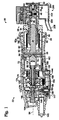
- Fig. 1 depicts a needle-free injection system 20 according to the invention, including an injection device 22.
- Fig. 1 shows injection device 22 in a first position, which will be referred to as the "primed” or “priming” position. Typically, the device is also placed in the position shown in Fig. 1 for storage and/or shipping.
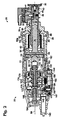
- Fig. 2 depicts device 22 in a position which will be referred to as the "primed” or “priming” position;
- Fig. 3 depicts device 22 in a position which will be referred to as the "fired” or “firing” position.
- Fig. 4 is an exploded view depicting various components that may be used to construct injection device 22.
- injection device 22 is configured to inject a dose of a drug or other fluid into a subject animal. This is accomplished by using pressurized gas to expel fluid from the injection device.
- the pressurized gas may be supplied from a tank, cartridge or other source, and typically is delivered through device 22 and vented via operation of various valve structures.
- System 20 may include a fluid supply 24 that may be coupled with injection device 22 in order to supply the injection device with fluid, such as drugs, vaccines or other injectable fluids.
- injection device 22 may include an outer housing 26, which typically is adapted to be comfortably held in a user's hand.
- the depicted housing is formed from injection-molded plastic, though various other materials and fabrication methods may be employed as desired.
- Injection device 22 typically includes a fluid expulsion mechanism, such as syringe assembly 28, that is configured to draw in and forcibly expel drugs or other fluids.
- syringe assembly 28 may be disposed at least partially within housing 26 toward a forward end of the housing.
- Syringe assembly 28 includes a nozzle 30, which is affixed to an end of a fluid cylinder 32 and sealed thereon with an o-ring 34.
- a plunger 36 is slidably disposed within fluid cylinder 32, thereby defining a variable-volume fluid reservoir 38. When plunger 36 is advanced (i.e., moved to the right in Figs. 1-3), fluid is expelled out of fluid reservoir 38 through a discharge outlet 40 provided in nozzle 30.
- plunger 36 i.e., moving the plunger to the left in Figs. 1-3
- fluid reservoir 38 typically is coupled with fluid supply 24.
- syringe assembly 28 is presented as an illustrative example only, and that other variable-volume devices may be employed.
- a squeezable bulb or elastomeric bladder may be used to expel fluid from injection device 22.
- outlet 40 and inlet 42 typically are provided with check valves to prevent backflow.
- Various types of valves may be used, though ball-type check valves have proved useful in the depicted embodiment.
- an outlet check ball 44 is disposed within an outlet check ball chamber 46.
- Outlet check ball 44 is held against a valve seat 48 as plunger 36 is retracted, to prevent fluid or contaminants from being drawn into fluid reservoir 38 through discharge outlet 40.
- a spring (not shown) may also be provided to urge the check ball to the left into the closed position.
- check ball 44 moves forward, away from engagement with seat 48, allowing fluid to pass around the check ball and out of nozzle 30 through outlet 40.
- Inlet 42 may also include a similar ball-type check valve 52, including a check ball (not shown) urged upward into a closed position against a valve seat.
- check valve 52 opens, allowing fluid from fluid supply 24 to be drawn through the check ball valve into fluid reservoir 38.
- a piston 60 may be secured to plunger 36.
- piston 60 is slidably disposed within a piston cylinder 62, and creates a substantially sealed interface with an interior wall 62 a of the piston cylinder.
- a poppet valve 64 opens, as shown in Fig. 3, pressurized gas from a gas reservoir 66 is allowed to escape past a gas bulkhead 68 through a bulkhead opening 70.
- Gas reservoir 66 is contained within a gas cylinder 72, which is fixedly secured relative to bulkhead 68 and piston cylinder 62.
- piston chamber 74 The area between bulkhead 68 and piston 60 created by the advancement of piston 60 will be referred to as piston chamber 74 (Fig. 3).
- a return spring 76 may be provided to urge piston 60 back toward bulkhead 68 upon venting of pressurized gas within piston chamber 74 and gas reservoir 66.
- Syringe assembly 28 may be configured with an adjustment capability to allow variation of the maximum amount of fluid that may be drawn into and expelled from fluid reservoir 38.
- the outer circumference of fluid cylinder 32 may include threads 80 configured to interface with corresponding threads on piston cylinder 62. Rotation of the fluid cylinder then varies the plunger's permitted range of motion, by adjusting the maximum amount by which plunger 36 may be withdrawn from fluid cylinder 32 before being blocked by bulkhead 68. This adjusts the maximum volume of fluid reservoir 38.
- a locking nut 84 may also be provided to retain fluid cylinder 32 in place relative to piston cylinder 62 once a desired volume has been selected.
- Indicia 85 may be provided on the outer surface of the fluid cylinder 32, or in another suitable location, to indicate the selected volume and/or the relative position of fluid cylinder 32 and piston cylinder 62.
- piston cylinder 62 typically is fixedly secured to gas bulkhead 68 and gas cylinder 72.
- a slidable valve structure 90 is fixedly secured to gas cylinder 72.
- Piston cylinder 62, gas cylinder 72 and slidable valve structure 90 collectively form a reciprocating structure 92 which moves back and forth relative to housing 26 along axis 94.
- Syringe assembly 28 is secured to the forward end of reciprocating structure 92, and thus also moves relative to housing 26.
- the forward end of reciprocating structure 92 is held within an aperture in housing 26, such that at least part of syringe assembly 28 sticks out of the forward end of housing 26.
- a wiper seal 96 may be provided within the aperture to contact the reciprocating structure (e.g., the outer surface of piston cylinder 62).
- slidable valve structure 90 is slidably supported within a valve body 100 that is fixedly secured within housing 26.
- reciprocating structure 92 is progressively pushed into housing 26 from the position shown in Fig. 1, to the position shown in Fig. 3. Normally, this occurs as a result of pressing nozzle 30 against an injection site while manually gripping housing 26.
- Spring 102 is compressed as reciprocating structure 92 moves in a rearward direction relative to housing 26. Upon removal of the compressing force, spring 102 urges reciprocating structure 92 back toward the position shown in Fig. 1.
- An adjustment bolt 104 or like device may be provided to adjust the degree to which reciprocating structure 92 may be pushed into housing 26. Specifically, as seen at the rear or left end of Fig. 3, the head of bolt 104 abuts the rear portion of the interior of housing 26 to prevent further rearward movement of reciprocating structure 92 relative to housing 26. Rotation of bolt 104 thus adjusts the available range of rearward travel of reciprocating structure 92.
- slidable valve structure 90 may include an inner valve sleeve 110 and an outer valve sleeve 112.
- outer valve sleeve 112 includes a first set of holes 114 which fluidly communicate with a bore passage 116 defined through the center of inner valve sleeve 110. Bore passage 116 fluidly couples with a poppet reservoir 118 defined in part by poppet 120.
- poppet 120 is slidably movable back and forth on the end of slidable valve structure 90. When poppet 120 is in its forward-most position, as shown in Figs. 1 and 2, poppet 120 seats into a valve seat in bulkhead 68, thus sealing off gas reservoir 66 from piston chamber 74. Fore-and-aft movement of poppet 120 typically is controlled by gas pressure existing in poppet reservoir 118 and gas reservoir 66.
- Outer valve sleeve 112 may include another set of holes 130, which fluidly communicate with a cylindrical passage 132. As indicated, passage 132 may be defined between the inner and outer valve sleeves. Cylindrical passage 132 fluidly couples with gas reservoir 66 via holes 134. The external surface of outer valve sleeve 112 may include a single, small groove 135 to provide a gas path between one of holes 130 and one of holes 114. This gas path provides a means of escape for exhaust gas at the conclusion of an injection sequence.
- a gas fitting 140 may be provided into housing 26, to enable the injection device to be supplied with compressed air or some other pressurized gas via a gas hose (not shown).
- the delivery of pressurized gas through the device typically is controlled via a supply valve assembly 142, which is actuated via operation of a trigger 144.
- supply valve assembly 142 may include a valve 146 biased into a closed position by a spring (not shown), a supply valve plunger 148 secured to supply valve 146, and a supply conduit 150 through which pressurized gas is provided upon opening of the valve.
- Trigger 144 is pivotally movable relative to housing 26 via a hinge 147 provided toward its rear end. Pushing the forward end of trigger 144 inward (or upward as depicted) causes valve plunger 148 to move upward. Upward movement of valve plunger 148 moves supply valve 146 upward into an open position, allowing pressurized gas to pass beyond supply valve 146 and be delivered to other parts of device 22 via a supply conduit 150.
- Valve body 100 includes a forward section 170, a rear section 172, and two intermediate sections 174 and 176.
- a spring 102 extends between and urges against forward section 170 and the rear end of gas cylinder 72.
- Three U-cup seals 180, 182 and 184 are provided between the pieces of the valve body.
- the area of intermediate section 176 between seals 182 and 184 provides a supply chamber 186 that is fluidly coupled with supply conduit 150 of supply valve assembly 142.
- the area of rear section 172 to the rear of seal 184 vents to atmosphere, as does the area of intermediate section 174 forward of seal 180.
- valve structure 90 moves slidable valve structure 90 backward and forward relative to valve body 100 (e.g., by pushing reciprocating structure 92 into housing 26) controls pressurization and venting of the various passages in slidable valve structure 90.
- valve structure 90 is positioned so that holes 114 in outer valve sleeve 112 are aligned slightly to the rear of seal 184, allowing bore passage 116 and poppet reservoir 118 to vent to atmosphere.
- holes 130 are aligned slightly to the front of seal 180, allowing cylindrical passage 132 and gas reservoir 66 to vent to atmosphere.
- holes 114 and/or holes 130 are at times aligned with supply chamber 186, such that the respective passages and reservoirs are equalized in pressure relative to the supply chamber. Accordingly, in such a state of alignment, opening supply valve 146 would pressurize the respective passages/reservoirs.
- injection device 22 may also include a dye marker 200.
- Dye marker 200 includes a dye reservoir 202 and a dye outlet 204.
- a pressure inlet 206 is coupled with a pressure source via a hose 208.
- Dye marker 200 is configured to apply a metered amount of marking dye to an injection site upon application of air pressure through hose 208.
- the pressure source is provided by the residual air pressure in gas reservoir 66 and piston chamber 74 as those areas are vented.
- hose 208 may be coupled to an exhaust port in housing 26 to fluidly couple dye marker 200 with venting passages within injection device 22.
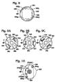
- FIGs. 11-15 depict a needle-free injection system 1020 according to another embodiment of the invention.
- Injection system 1020 includes an injection device 1022.
- Fig. 11 shows injection device 1022 in a first position. Typically, the device is placed in the position shown in Fig. 11 for storage and/or shipping, and thus, this position may be referred to as the "storage" position.
- Fig. 12 depicts device 1022 in a position which will be referred to as the "primed,” or “priming” position.
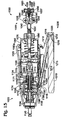
- Fig. 13 depicts device 1022 in a position which will be referred to as the "fired" or “firing” position.
- Fig. 14 depicts device 1022 in the storage position shown in Fig. 11, but rotated 90 degrees along the horizontal axis to show a top sectional view.
- Fig. 15 depicts device 1022 in the fired position shown in Fig. 13, but rotated 90 degrees along the horizontal axis to show a top sectional view.
- injection device 1022 is configured to inject a dose of a drug or other fluid into a subject animal. This is accomplished by using pressurized gas to expel fluid from the injection device.
- the pressurized gas may be supplied from a tank, cartridge or other source, and typically is delivered through device 1022 and vented via operation of various valve structures.
- System 1020 may include a fluid supply (not shown) that may be coupled with injection device 1022 in order to supply the injection device with fluid, such as drugs, vaccines or other injectable fluids.
- injection device 1022 may include an outer housing 1026, which typically is adapted to be comfortably held in a user's hand.
- the depicted housing is formed from injection-molded plastic, though various other materials and fabrication methods may be employed as desired.
- Injection device 1022 typically includes a fluid expulsion mechanism, such as syringe assembly 1028, that is configured to draw in and forcibly expel drugs or other fluids.
- syringe assembly 1028 may be disposed at least partially within housing 1026 toward a forward end of the housing.
- Syringe assembly 1028 includes a disposable nozzle assembly 1030.
- Detachable nozzle assembly 1030 includes a disposable end cap 1031 and a disposable nozzle 1033.
- End cap 1031 is detachably connected to a retaining structure 1035, and may be sealed thereon by an o-ring 1037.
- Nozzle 1033 may be detachably seated into retaining structure 1035, and defines discharge outlet 1040.
- O-ring 1034 may provide a seal between disposable nozzle 1033 and fluid cylinder 1032.
- End cap 1031, nozzle 1033, and retaining structure 1035 may be formed out of any suitable material or materials including, for example, plastic or metal.
- end cap 1031 and nozzle 1033 may be formed of plastic, while retaining structure 1035 may be formed of metal.
- a plunger 1036 is slidably disposed within fluid cylinder 1032, thereby defining a variable-volume fluid reservoir 1038.
- plunger 1036 When plunger 1036 is advanced (i.e., moved to the right in Figs. 11-14), fluid is expelled out of fluid reservoir 1038 via fluid path 1039 and through a discharge outlet 1040 provided in nozzle 1030.
- Retraction of plunger 1036 i.e., moving the plunger to the left in Figs. 11-15) draws fluid into fluid reservoir 1038 through inlet 1042, which typically is coupled with a fluid supply via connecting assembly 1025.
- the connection between inlet 1042 and fluid path 1039 may be sealed by an o-ring 1043.
- syringe assembly 1028 is presented as an illustrative example only, and that other variable-volume devices may be employed.
- a squeezable bulb or elastomeric bladder may be used to expel fluid from injection device 1022.
- outlet 1040 and inlet 1042 typically are provided with check valves to prevent backflow.
- valves Various types may be used, including ball-type check valves.
- an outlet check ball 1044 is disposed within an outlet check ball chamber 1046.
- Outlet check ball 1044 is held against a valve seat 1048 as plunger 1036 is retracted, to prevent fluid or contaminants from being drawn into fluid reservoir 1038 through discharge outlet 1040.
- a spring 1045 may also be provided to urge the check ball towards valve seat 1048 and into the closed position. Spring 1045 may be retained in place by a retaining structure 1047.
- Retaining structure 1047 may, for example, be formed of plastic or any other suitable material.
- Inlet 1042 may also include a similar ball-type check valve including a check ball 1052 urged upward into a closed position against a valve seat 1051. Again, a spring 1053 may be provided to urge check ball 1052 into valve seat 1051 and into the closed position.
- check valve 1052 opens, allowing fluid from fluid supply 1024 to be drawn through the check ball valve into fluid reservoir 1038.
- a piston 1060 may be secured to plunger 1036.
- piston 1060 is slidably disposed within a piston cylinder 1062, and creates a substantially sealed interface with an interior wall 1062 a of the piston cylinder.
- a poppet valve 1064 opens, as shown in Fig. 13, pressurized gas from a gas reservoir 1066 is allowed to escape past a gas bulkhead 1068 through a bulkhead opening 1070.
- Gas reservoir 1066 is contained within a gas cylinder 1072, which is fixedly secured relative to bulkhead 1068 and piston cylinder 1062.
- piston 1060 a of piston 1060 Upon the opening of poppet valve 1064, the pressurized gas exerts upon operative surface 1060 a of piston 1060, causing piston 1060 and plunger 1036 to advance forward and expel fluid from syringe assembly 1028 through discharge outlet 1040.
- piston chamber 1074 The area between bulkhead 1068 and piston 1060 created by the advancement of piston 1060 will be referred to as piston chamber 1074 (Fig. 13).
- a return spring 1076 may be provided to urge piston 1060 back toward bulkhead 1068 upon venting of pressurized gas within piston chamber 1074 and gas reservoir 1066.
- Syringe assembly 1028 may be configured with an adjustment capability to allow variation of the maximum amount of fluid that may be drawn into and expelled from fluid reservoir 1038.
- the outer circumference of fluid cylinder 1032 may include threads 1080 configured to interface with corresponding threads on piston cylinder 1062. Rotation of the fluid cylinder then varies the plunger's permitted range of motion, by adjusting the maximum amount by which plunger 1036 may be withdrawn from fluid cylinder 1032 before being blocked by bulkhead 1068. This adjusts the maximum volume of fluid reservoir 1038.
- a locking nut 1084 may also be provided to retain fluid cylinder 1032 in place relative to piston cylinder 1062 once a desired volume has been selected. While not shown, as with the embodiment described with respect to Figs. 1-3, indicia may be provided on the outer surface of the fluid cylinder 1032, or in another suitable location, to indicate the selected volume and/or the relative position of fluid cylinder 1032 and piston cylinder 1062.
- piston cylinder 1062 typically is fixedly secured to gas bulkhead 1068 and gas cylinder 1072.
- a slidable valve structure 1090 is fixedly secured to gas cylinder 1072.
- Piston cylinder 1062, gas cylinder 1072 and slidable valve structure 1090 collectively form a reciprocating structure 1092 which moves back and forth relative to housing 1026 along axis 1094.
- Syringe assembly 1028 is secured to the forward end of reciprocating structure 1092, and thus also moves relative to housing 1026.
- the forward end of reciprocating structure 1092 is held within an aperture in housing 1026, such that at least part of syringe assembly 1028 sticks out of the forward end of housing 1026.
- a wiper seal 1096 may be provided within the aperture to contact the reciprocating structure (e.g., the outer surface of piston cylinder 1062).
- slidable valve structure 1090 is slidably supported within a valve body 1100 that is fixedly secured within housing 1026.
- reciprocating structure 1092 is progressively pushed into housing 1026 from the position shown in Fig. 11, to the position shown in Fig. 13. Normally, this occurs as a result of pressing nozzle 1030 against an injection site while manually gripping housing 1026.
- Spring 1102 is compressed as reciprocating structure 1092 moves in a rearward direction relative to housing 1026. Upon removal of the compressing force, spring 1102 urges reciprocating structure 1092 back toward the position shown in Fig. 11.
- An adjustment bolt 1104 or like device may be provided to adjust the degree to which reciprocating structure 1092 may be pushed into housing 1026. Specifically, as seen at the rear or left end of Fig. 13, the head of bolt 1104 abuts the rear portion of the interior of housing 1026 to prevent further rearward movement of reciprocating structure 1092 relative to housing 1026. Rotation of bolt 1104 thus adjusts the available range of rearward travel of reciprocating structure 1092.
- slidable valve structure 1090 may include an inner valve sleeve 1110 and an outer valve sleeve 1112.
- outer valve sleeve 1112 includes a first set of holes 1114 which fluidly communicate with a bore passage 1116 defined through the center of inner valve sleeve 1110. Bore passage 1116 fluidly couples with a poppet reservoir 1118 defined in part by poppet seat 1119.
- Poppet seat 1119 is adapted to retain a poppet 1120.
- poppet seat 1119 is slidably movable back and forth on the end of slidable valve structure 1090. When poppet seat 1119 is in its forward-most position, as shown in Fig.
- poppet 1120 seats into a valve seat in bulkhead 1068, thus sealing off gas reservoir 1066 from piston chamber 1074.
- Fore-and-aft movement of poppet seat 1119 typically is controlled by gas pressure existing in poppet reservoir 1118 and gas reservoir 1066.
- Outer valve sleeve 1112 may include another set of holes 1130, which fluidly communicate with a cylindrical passage 1132. As indicated, passage 1132 may be defined between the inner and outer valve sleeves. Cylindrical passage 1132 fluidly couples with gas reservoir 1066 via holes 1134. The external surface of the outer valve sleeve 1112 may include a single, small groove, 1135 (shown in Figs. 14 and 15) to provide a gas path between one of holes 130 and one of holes 114. This gas path provides a means of escape for exhaust gas at the conclusion of an injection sequence.
- a gas fitting 1140 may be provided into housing 1026, to enable the injection device to be supplied with compressed air or some other pressurized gas via a gas hose (not shown).
- the delivery of pressurized gas through the device typically is controlled via a supply valve assembly 1142, which is actuated via operation of a trigger 1144.
- supply valve assembly 1142 may include a valve 1146 biased into a closed position by a spring 1145, a supply valve plunger 1148 secured to supply valve 1146, and a supply conduit 1150 through which pressurized gas is provided upon opening of the valve.
- Trigger 1144 is pivotally movable relative to housing 1026 via a hinge 1147 provided toward its rear end. Pushing the forward end of trigger 1144 inward (or upward as depicted) causes valve plunger 1148 to move upward. Upward movement of valve plunger 1148 moves supply valve 1146 upward into an open position, allowing pressurized gas to pass beyond supply valve 1146 and be delivered to other parts of device 1022 via a supply conduit 1150.
- Valve body 1100 includes a forward section 1170, a rear section 1172, and an intermediate section 1174.
- a spring 1102 extends between and urges against a recessed region 1171 of forward section 1170 and the rear end of gas cylinder 1072.
- Three U-cup seals 1180, 1182 and 1184 are provided between the pieces of the valve body. The area of rear section 1172 between seals 1182 and 1184 provides a supply chamber 1186 that is fluidly coupled with supply conduit 1150 of supply valve assembly 1142.
- valve structure 1090 moves slidable valve structure 1090 backward and forward relative to valve body 1100 (e.g., by pushing reciprocating structure 1092 into housing 1026) controls pressurization and venting of the various passages in slidable valve structure 1090.
- valve structure 1090 is positioned so that holes 1114 in outer valve sleeve 1112 are aligned slightly to the rear of seal 1184, allowing bore passage 1116 and poppet reservoir 1118 to vent to atmosphere.
- holes 1130 are aligned slightly to the front of seal 1182, allowing cylindrical passage 1132 and gas reservoir 1066 to vent to atmosphere.
- holes 1114 and/or holes 1130 are at times aligned with supply chamber 1186, such that the respective passages and reservoirs are equalized in pressure relative to the supply chamber. Accordingly, in such a state of alignment, opening supply valve 1146 would pressurize the respective passages/reservoirs.
- injection device 1022 may also include a marking assembly 1200.
- Marking assembly 1200 is connected to outer housing 1026 of device 1022 by supporting structure 1210.
- supporting structure 1210 may terminate in a housing 1212, which is adapted to receive and secure a fluid reservoir 1214.
- fluid reservoir 1214 includes a fluid chamber 1215 in fluid communication with a nib 1218, which extends out of the fluid chamber.
- Nib 1218 typically acts as a wick, drawing fluid out of reservoir 1214.
- reservoir 1214 holds ink or some other fluid capable of leaving a detectable mark on the surface (i.e., skin, hide, or hair) of an injection recipient.
- fluid reservoir 1214 may take the form of a writing instrument, or marker 1219. Suitable markers include the Sharpie® writing instruments sold by Sanford Corp. (Bellwood, IL).
- housing 1212 defines a chamber 1216 near nib 1218 of marker 1202.
- Chamber 1216 includes an outlet 1220, surrounding nib 1218.
- Outlet 1220 may, for example, be conical in shape, extending from nib 1218 outwards, as shown, thereby creating a shaped venture channel.
- Air passage 1222 extends from chamber 1216 through supporting structure 1210 and into device 1022, where it communicates with supply conduit 1224.
- Supply conduit 1224 is adapted to communicate with holes 1130 in slidable valve structure 1090 when the slidable valve structure is moved from the fired position (shown in Fig. 14) to the storage position (shown in Fig. 15).
- At least a portion of the exhaust gas in gas reservoir 1066 and piston chamber 1074 may be vented into chamber 1216, such that the airflow through chamber 1216 is directed past nib 1218, drawing fluid from nib 1218 out of outlet 1220 and onto the surface of the injection recipient.
- injection device 22 will now be described with reference to Figs. 1-3. It should be appreciated that, unless otherwise indicated, injection device 1022 will operate in a substantially similar manner. Injection device 22 is prepared for initial use by coupling a hose (not shown) from a compressed air tank or other supply of pressurized gas to fitting 140. Injection device 22 is then fired one or more times, in the manner to be described below, in order to expel air from fluid reservoir 38 and draw a full metered dose of injectable fluid into the fluid reservoir. Operation of the injection device will be described assuming the device is initially in the position shown in Fig. 1.
- the operator grips outer housing 26, and presses trigger 144 inward, opening supply valve 146, which causes pressurized gas to flow through supply conduit 150 into supply chamber 186.
- holes 114 are aligned with supply chamber 186.
- Bore passage 116 is thus pressurized by the opening of supply valve 146, which causes poppet 120 to move forward and close the poppet valve, sealing off bulkhead 68 between gas reservoir 66 and piston chamber 74.
- Trigger 144 is depressed further, causing reciprocating structure 92 to be pushed somewhat into housing 26, moving device 22 from the storage position shown in Fig. 1 to the primed position shown in Fig. 2.
- holes 114 are still aligned with supply chamber 186, but the slidable valve assembly has moved far enough rearward so that holes 130 are now also aligned with supply chamber 186.
- gas reservoir 66 is pressurized (charged) via holes 130 and cylindrical passage 132.
- Poppet reservoir 118 remains pressurized in Fig. 2, such that poppet valve 64 is held closed and no gas escapes into piston chamber 74.
- Plunger 36 thus remains in its fully withdrawn position.
- Fig. 2 shows trigger 144 un-depressed, it should be appreciated that the trigger is held depressed long enough to allow air delivered through supply valve 146 to charge gas reservoir 66.
- poppet 120 may be sized so that it covers holes 134 when in its rearmost position. This closes off channel 132 to prevent unnecessary waste of pressurized gas, by preventing further delivery of gas into gas reservoir 66.
- Fig. 3 shows piston 60 in its fully advanced position, and reciprocating structure 92 in its rearmost position relative to housing 26.
- gas reservoir 66 and piston chamber 74 have not yet vented, and those areas remain at a substantial pressure differential above atmosphere. Piston 60 thus remains advanced.
- spring 102 urges reciprocating structure 92 forward relative to housing 26. This in turn causes slidable valve structure 90 to move relative to valve body 100.
- gas reservoir 66 and piston chamber 74 are vented when holes 130 and groove 135 of valve structure 90 pass forward beyond U-cup seal 180.
- spring 76 urges against piston 60, causing it to return from its advanced position to its retracted position against bulkhead 68, as seen in Figs.
- the exhaust gas may be used to actuate dye marker 200, by fluidly coupling the venting chamber and dye marker with hose 208.
- the exhaust gas may be directed past nib 1218, drawing marking fluid from nib 1218, out of outlet 1220, and onto the surface of the injection recipient.
- plunger 36 As piston 60 retracts, plunger 36 is retracted from its advanced position within fluid reservoir 38. The retreat of plunger 36 opens inlet check valve 52 and draws a new dose of fluid into fluid reservoir 38. The outlet check valve remains closed, due to its spring and the vacuum pressure created by the retraction of plunger 36. Eventually, the device returns to the position shown in Fig. 1 and is ready to deliver another injection of fluid in the manner just described.
Landscapes
- Health & Medical Sciences (AREA)
- Vascular Medicine (AREA)
- Engineering & Computer Science (AREA)
- Anesthesiology (AREA)
- Biomedical Technology (AREA)
- Heart & Thoracic Surgery (AREA)
- Hematology (AREA)
- Life Sciences & Earth Sciences (AREA)
- Animal Behavior & Ethology (AREA)
- General Health & Medical Sciences (AREA)
- Public Health (AREA)
- Veterinary Medicine (AREA)
- Infusion, Injection, And Reservoir Apparatuses (AREA)
Applications Claiming Priority (2)
| Application Number | Priority Date | Filing Date | Title |
|---|---|---|---|
| US10/458,345 US7156823B2 (en) | 2002-06-04 | 2003-06-09 | High workload needle-free injection system |
| EP04752509A EP1636090A4 (fr) | 2003-06-09 | 2004-05-12 | Systeme d'injection sans aiguille a haut rendement |
Related Parent Applications (1)
| Application Number | Title | Priority Date | Filing Date |
|---|---|---|---|
| EP04752509A Division EP1636090A4 (fr) | 2003-06-09 | 2004-05-12 | Systeme d'injection sans aiguille a haut rendement |
Publications (2)
| Publication Number | Publication Date |
|---|---|
| EP1745814A2 true EP1745814A2 (fr) | 2007-01-24 |
| EP1745814A3 EP1745814A3 (fr) | 2007-03-14 |
Family
ID=33551318
Family Applications (2)
| Application Number | Title | Priority Date | Filing Date |
|---|---|---|---|
| EP06021355A Withdrawn EP1745814A3 (fr) | 2003-06-09 | 2004-05-12 | Système d'injection sans aiguille |
| EP04752509A Withdrawn EP1636090A4 (fr) | 2003-06-09 | 2004-05-12 | Systeme d'injection sans aiguille a haut rendement |
Family Applications After (1)
| Application Number | Title | Priority Date | Filing Date |
|---|---|---|---|
| EP04752509A Withdrawn EP1636090A4 (fr) | 2003-06-09 | 2004-05-12 | Systeme d'injection sans aiguille a haut rendement |
Country Status (4)
| Country | Link |
|---|---|
| US (1) | US7156823B2 (fr) |
| EP (2) | EP1745814A3 (fr) |
| CA (1) | CA2531205C (fr) |
| WO (1) | WO2005000680A2 (fr) |
Families Citing this family (59)
| Publication number | Priority date | Publication date | Assignee | Title |
|---|---|---|---|---|
| GB0100756D0 (en) | 2001-01-11 | 2001-02-21 | Powderject Res Ltd | Needleless syringe |
| EP1635896A1 (fr) * | 2003-06-20 | 2006-03-22 | Allergan, Inc. | Injecteurs sans aiguille |
| GB2410188B (en) * | 2004-01-23 | 2006-01-25 | Medical House Plc | Injection device |
| GB2410190A (en) * | 2004-01-26 | 2005-07-27 | Medical House Plc | Disposable gas-powered needle-free injection device |
| GB2414409B (en) * | 2004-05-28 | 2009-11-18 | Cilag Ag Int | Injection device |
| GB2414406B (en) | 2004-05-28 | 2009-03-18 | Cilag Ag Int | Injection device |
| GB2414401B (en) | 2004-05-28 | 2009-06-17 | Cilag Ag Int | Injection device |
| GB2414404B (en) | 2004-05-28 | 2009-06-03 | Cilag Ag Int | Injection device |
| GB2414399B (en) * | 2004-05-28 | 2008-12-31 | Cilag Ag Int | Injection device |
| GB2414402B (en) * | 2004-05-28 | 2009-04-22 | Cilag Ag Int | Injection device |
| GB2414405B (en) * | 2004-05-28 | 2009-01-14 | Cilag Ag Int | Injection device |
| GB2414403B (en) * | 2004-05-28 | 2009-01-07 | Cilag Ag Int | Injection device |
| GB2414775B (en) * | 2004-05-28 | 2008-05-21 | Cilag Ag Int | Releasable coupling and injection device |
| US7717874B2 (en) * | 2004-05-28 | 2010-05-18 | Bioject, Inc. | Needle-free injection system |
| GB2414400B (en) * | 2004-05-28 | 2009-01-14 | Cilag Ag Int | Injection device |
| BRPI0515759B8 (pt) | 2004-12-01 | 2021-06-22 | Acushot Inc | dispositivo de injeção sem agulha e kit para utilização do mesmo |
| GB2424836B (en) * | 2005-04-06 | 2010-09-22 | Cilag Ag Int | Injection device (bayonet cap removal) |
| GB2425062B (en) * | 2005-04-06 | 2010-07-21 | Cilag Ag Int | Injection device |
| GB2424837B (en) * | 2005-04-06 | 2010-10-06 | Cilag Ag Int | Injection device |
| GB2424838B (en) * | 2005-04-06 | 2011-02-23 | Cilag Ag Int | Injection device (adaptable drive) |
| GB2427826B (en) | 2005-04-06 | 2010-08-25 | Cilag Ag Int | Injection device comprising a locking mechanism associated with integrally formed biasing means |
| GB2424835B (en) * | 2005-04-06 | 2010-06-09 | Cilag Ag Int | Injection device (modified trigger) |
| DE602005018480D1 (de) * | 2005-08-30 | 2010-02-04 | Cilag Gmbh Int | Nadelvorrichtung für eine vorgefüllte Spritze |
| US20110098656A1 (en) | 2005-09-27 | 2011-04-28 | Burnell Rosie L | Auto-injection device with needle protecting cap having outer and inner sleeves |
| GB0601309D0 (en) * | 2006-01-23 | 2006-03-01 | Medical House The Plc | Injection device |
| US20070173770A1 (en) | 2006-01-23 | 2007-07-26 | The Medical House Plc | Injection device |
| GB2438591B (en) * | 2006-06-01 | 2011-07-13 | Cilag Gmbh Int | Injection device |
| GB2438590B (en) | 2006-06-01 | 2011-02-09 | Cilag Gmbh Int | Injection device |
| GB2438593B (en) | 2006-06-01 | 2011-03-30 | Cilag Gmbh Int | Injection device (cap removal feature) |
| AU2007257173B2 (en) * | 2006-06-07 | 2013-03-14 | Acushot Inc. | Charging mechanism for a needle-free injector |
| US7942845B2 (en) * | 2006-09-19 | 2011-05-17 | Bioject, Inc. | Needle-free injector and process for providing serial injections |
| US7547293B2 (en) * | 2006-10-06 | 2009-06-16 | Bioject, Inc. | Triggering mechanism for needle-free injector |
| US7637889B2 (en) * | 2006-11-15 | 2009-12-29 | Glynntech, Inc. | Drug delivery device with sliding valve and methodology |
| US8382713B2 (en) * | 2006-12-11 | 2013-02-26 | Kenergy Scientific, Inc. | Drug delivery device and methodology |
| GB0625169D0 (en) | 2006-12-18 | 2007-01-24 | Medical House Plc The | Improved autoinjector |
| US7744563B2 (en) * | 2007-02-23 | 2010-06-29 | Bioject, Inc. | Needle-free injection devices and drug delivery systems therefor |
| GB0704351D0 (en) * | 2007-03-07 | 2007-04-11 | Medical House Plc The | Improved autoinjector |
| GB0708758D0 (en) | 2007-05-04 | 2007-06-13 | Powderject Res Ltd | Particle cassettes and process thereof |
| US8617099B2 (en) * | 2007-11-26 | 2013-12-31 | Bioject Inc. | Injection device plunger auto-disable |
| US20090137949A1 (en) * | 2007-11-26 | 2009-05-28 | Bioject Inc. | Needle-free injection device with nozzle auto-disable |
| GB2461086B (en) * | 2008-06-19 | 2012-12-05 | Cilag Gmbh Int | Injection device |
| GB2461084B (en) * | 2008-06-19 | 2012-09-26 | Cilag Gmbh Int | Fluid transfer assembly |
| GB2461087B (en) * | 2008-06-19 | 2012-09-26 | Cilag Gmbh Int | Injection device |
| GB2461088B (en) * | 2008-06-19 | 2012-09-26 | Cilag Gmbh Int | Injection device |
| GB2461085B (en) | 2008-06-19 | 2012-08-29 | Cilag Gmbh Int | Injection device |
| GB2461089B (en) * | 2008-06-19 | 2012-09-19 | Cilag Gmbh Int | Injection device |
| WO2010033882A2 (fr) * | 2008-09-18 | 2010-03-25 | Becton, Dickinson And Company | Injecteur médical avec activation par manchon coulissant |
| EP2193817A1 (fr) * | 2008-12-02 | 2010-06-09 | Sanofi-Aventis Deutschland GmbH | Ensemble de commande adapté pour un dispositif d'administration de médicaments et dispositif d'administration de médicaments |
| GB2469672B (en) | 2009-04-23 | 2013-09-25 | Medical House Ltd | Improved autoinjector |
| WO2010135840A1 (fr) * | 2009-05-28 | 2010-12-02 | Medical International Technologies (Mit Canada) Inc. | Accessoires d'injecteur sans aiguille |
| CN102178990B (zh) * | 2010-01-08 | 2013-10-09 | 江苏丞宇米特医疗科技有限公司 | 无针注射器 |
| TWI417120B (zh) * | 2011-05-27 | 2013-12-01 | Leader Machine Co Ltd | A drug delivery device with built - in quantitative pusher |
| DE102011119056A1 (de) * | 2011-11-16 | 2014-02-27 | Lts Lohmann Therapie-Systeme Ag | Zylinder-Kolben-Einheit mit Berstventil |
| US9808579B2 (en) | 2013-05-08 | 2017-11-07 | Elwha Llc | Needleless injector systems, and related methods and components |
| GB2517896B (en) | 2013-06-11 | 2015-07-08 | Cilag Gmbh Int | Injection device |
| GB2515039B (en) | 2013-06-11 | 2015-05-27 | Cilag Gmbh Int | Injection Device |
| GB2515032A (en) | 2013-06-11 | 2014-12-17 | Cilag Gmbh Int | Guide for an injection device |
| GB2515038A (en) | 2013-06-11 | 2014-12-17 | Cilag Gmbh Int | Injection device |
| JP2023540567A (ja) * | 2020-09-09 | 2023-09-25 | ザ トラスティーズ オブ ザ ユニバーシティ オブ ペンシルバニア | 無針注射器、関連付けられた再装填可能かつ廃棄可能なノズル及び注射方法 |
Family Cites Families (52)
| Publication number | Priority date | Publication date | Assignee | Title |
|---|---|---|---|---|
| DE895129C (de) | 1944-04-07 | 1953-10-29 | Ulrich Dr-Ing Huetter | Windkraftanlage zur Erzeugung von elektrischem Strom |
| US2680439A (en) | 1948-09-08 | 1954-06-08 | Arnold K Sutermeister | High-pressure injection device |
| US2653604A (en) | 1950-12-19 | 1953-09-29 | Jr George N Hein | Injection device |
| US3202151A (en) * | 1963-04-08 | 1965-08-24 | Scherer Corp R P | Multidose jet injector |
| US3859996A (en) | 1973-07-18 | 1975-01-14 | Mizzy Inc | Multi-dose injector |
| JPS51130094A (en) * | 1975-05-08 | 1976-11-12 | Asahi Chemical Ind | Twoostage pressure injector |
| USD277506S (en) | 1981-09-15 | 1985-02-05 | Bearn Mecanique Aviation S.A. | Needle-less injection instrument |
| US4596556A (en) | 1985-03-25 | 1986-06-24 | Bioject, Inc. | Hypodermic injection apparatus |
| US4739973A (en) | 1986-08-13 | 1988-04-26 | Herndon J Marvin | Chemical extraction of metals from ores |
| US6056716A (en) * | 1987-06-08 | 2000-05-02 | D'antonio Consultants International Inc. | Hypodermic fluid dispenser |
| US4940460A (en) | 1987-06-19 | 1990-07-10 | Bioject, Inc. | Patient-fillable and non-invasive hypodermic injection device assembly |
| US4941880A (en) | 1987-06-19 | 1990-07-17 | Bioject, Inc. | Pre-filled ampule and non-invasive hypodermic injection device assembly |
| US4790824A (en) | 1987-06-19 | 1988-12-13 | Bioject, Inc. | Non-invasive hypodermic injection device |
| BR8801952A (pt) | 1988-04-22 | 1989-11-14 | Sergio Landau | Capsula descartavel,nao re-utilizavel,contendo dose individual de vacina a ser injetada hipodermicamente,sem agulha,com aparelho injetor a pressao |
| AU6550990A (en) * | 1989-11-09 | 1991-05-16 | Bioject, Inc. | Needleless hypodermic injection device |
| US5064413A (en) | 1989-11-09 | 1991-11-12 | Bioject, Inc. | Needleless hypodermic injection device |
| US5312335A (en) | 1989-11-09 | 1994-05-17 | Bioject Inc. | Needleless hypodermic injection device |
| US5312577A (en) | 1992-05-08 | 1994-05-17 | Bioject Inc. | Method for manufacturing an ampule |
| US5383851A (en) | 1992-07-24 | 1995-01-24 | Bioject Inc. | Needleless hypodermic injection device |
| USD349958S (en) | 1992-07-24 | 1994-08-23 | Bioject Inc. | Needleless injector |
| US5746714A (en) | 1993-04-05 | 1998-05-05 | P.A.T.H. | Air powered needleless hypodermic injector |
| TW360548B (en) | 1993-04-08 | 1999-06-11 | Powderject Res Ltd | Products for therapeutic use |
| ATE197904T1 (de) | 1993-07-31 | 2000-12-15 | Weston Medical Ltd | Nadelloser injektor |
| GB9320798D0 (en) | 1993-10-08 | 1993-12-01 | Lucas Ind Plc | Fuel injection nozzle |
| WO1995024176A1 (fr) | 1994-03-07 | 1995-09-14 | Bioject, Inc. | Dispositif de remplissage d'ampoule |
| US5466220A (en) | 1994-03-08 | 1995-11-14 | Bioject, Inc. | Drug vial mixing and transfer device |
| FR2718357B1 (fr) | 1994-04-06 | 1997-10-03 | Defarges Alain Moreau | Perfectionnements apportés à un dispositif d'injection par jet sans aiguille. |
| DE29507987U1 (de) | 1995-05-15 | 1996-09-19 | Ferton Holding, Delemont | Ejektionsgerät zur Hochdruckejektion einer Flüssigkeit |
| US5893397A (en) | 1996-01-12 | 1999-04-13 | Bioject Inc. | Medication vial/syringe liquid-transfer apparatus |
| US5865795A (en) * | 1996-02-29 | 1999-02-02 | Medi-Ject Corporation | Safety mechanism for injection devices |
| US5782802A (en) | 1996-03-22 | 1998-07-21 | Vitajet Corporation | Multiple use needle-less hypodermic injection device for individual users |
| US5993412A (en) | 1997-05-19 | 1999-11-30 | Bioject, Inc. | Injection apparatus |
| USD399951S (en) | 1997-06-30 | 1998-10-20 | Bioject, Inc. | Injection apparatus |
| EP0888790A1 (fr) * | 1997-07-04 | 1999-01-07 | PowderJect Research Limited | Appareil d'apport de particules medicamenteuses |
| US6610042B2 (en) | 1997-12-05 | 2003-08-26 | Felton Medical, Inc. | Disposable unit-dose jet-injection syringe for pre-filled and/or transfilled liquid injectable medical drug or vaccine products and method thereof |
| US6506177B2 (en) | 1998-10-14 | 2003-01-14 | Sergio Landau | Needle-less injection system |
| US6096002A (en) | 1998-11-18 | 2000-08-01 | Bioject, Inc. | NGAS powered self-resetting needle-less hypodermic jet injection apparatus and method |
| US6264629B1 (en) | 1998-11-18 | 2001-07-24 | Bioject, Inc. | Single-use needle-less hypodermic jet injection apparatus and method |
| US6383168B1 (en) | 1998-12-08 | 2002-05-07 | Bioject Medical Technologies Inc. | Needleless syringe with prefilled cartridge |
| US6132395A (en) | 1998-12-08 | 2000-10-17 | Bioject, Inc. | Needleless syringe with prefilled cartridge |
| US6849060B1 (en) * | 1999-01-29 | 2005-02-01 | Powderject Research Limited | Particle delivery device |
| US6447351B1 (en) | 1999-06-17 | 2002-09-10 | Yamaha Hatsudoki Kabushiki Kaisha | Vapor system arrangement for marine engine |
| US6319224B1 (en) | 1999-08-20 | 2001-11-20 | Bioject Medical Technologies Inc. | Intradermal injection system for injecting DNA-based injectables into humans |
| ATE285806T1 (de) * | 1999-10-11 | 2005-01-15 | Felton International Inc | Universelle antiinfektionsschutzvorrichtung für nadellose injektoren |
| US7074210B2 (en) | 1999-10-11 | 2006-07-11 | Felton International, Inc. | Universal protector cap with auto-disable features for needle-free injectors |
| US7887506B1 (en) * | 1999-11-23 | 2011-02-15 | Pulse Needlefree Systems, Inc. | Safety mechanism to prevent accidental patient injection and methods of same |
| US6602222B1 (en) | 2000-10-13 | 2003-08-05 | Cambridge Biostability Ltd. | Disposable injection device |
| US6645170B2 (en) | 2001-03-05 | 2003-11-11 | Bioject Medical Technologies, Inc. | Simplified disposable needle-free injection apparatus and method |
| US6471669B2 (en) | 2001-03-05 | 2002-10-29 | Bioject Medical Technologies Inc. | Disposable needle-free injection apparatus and method |
| US6585685B2 (en) | 2001-06-08 | 2003-07-01 | Bioject Inc. | Jet injector apparatus and method |
| US6607510B2 (en) | 2001-11-09 | 2003-08-19 | Bioject Medical Technologies Inc. | Disposable needle-free injection apparatus and method |
| US6676630B2 (en) * | 2002-06-04 | 2004-01-13 | Bioject Medical Technologies, Inc. | Needle-free injection system |
-
2003
- 2003-06-09 US US10/458,345 patent/US7156823B2/en not_active Expired - Fee Related
-
2004
- 2004-05-12 WO PCT/US2004/015508 patent/WO2005000680A2/fr not_active Ceased
- 2004-05-12 EP EP06021355A patent/EP1745814A3/fr not_active Withdrawn
- 2004-05-12 EP EP04752509A patent/EP1636090A4/fr not_active Withdrawn
- 2004-05-12 CA CA2531205A patent/CA2531205C/fr not_active Expired - Fee Related
Also Published As
| Publication number | Publication date |
|---|---|
| EP1636090A2 (fr) | 2006-03-22 |
| CA2531205C (fr) | 2013-07-23 |
| CA2531205A1 (fr) | 2005-01-06 |
| WO2005000680A2 (fr) | 2005-01-06 |
| US20040111054A1 (en) | 2004-06-10 |
| EP1745814A3 (fr) | 2007-03-14 |
| EP1636090A4 (fr) | 2008-03-12 |
| WO2005000680A3 (fr) | 2006-02-02 |
| US7156823B2 (en) | 2007-01-02 |
Similar Documents
| Publication | Publication Date | Title |
|---|---|---|
| EP1745814A2 (fr) | Système d'injection sans aiguille | |
| US6676630B2 (en) | Needle-free injection system | |
| US6425897B2 (en) | Pistol for the pressing out of bone cement with an attachable cement syringe | |
| US8105272B2 (en) | Triggering mechanism for a needle-free injector | |
| US4007739A (en) | Fluid-operated hypodermic syringe | |
| CA1277196C (fr) | Actionneur de seringue tenu a la main | |
| US2821981A (en) | Multi-shot inoculant injector instrument with adjustable ejection pressure control | |
| US4717384A (en) | Pneumatic hypodermic syringe pole | |
| US7942845B2 (en) | Needle-free injector and process for providing serial injections | |
| US20070043319A1 (en) | Needlless injectors | |
| JP3493469B2 (ja) | 液体の材料を送出する器具、粘性質又は半粘性質の材料用の分配用器具及び液体の製品を分配する器具 | |
| US7238167B2 (en) | Needle-free injection system | |
| EP0915726A1 (fr) | Pistolet a eau a remplissage commande par le vide | |
| US20020016127A1 (en) | Water gun having pump with internal passageway | |
| WO2006073394A1 (fr) | Systeme d’injection sans aiguille | |
| US2687724A (en) | Inoculant injector instrument | |
| US20200261933A1 (en) | Paint sprayer | |
| AU2007261483A1 (en) | Steady stream water gun | |
| WO2000030704A1 (fr) | Dispositif d'injection multidose par jet ameliore sans aiguille | |
| TW202507180A (zh) | 閥致動器 | |
| CA2021567C (fr) | Injecteur et seringue uniservice | |
| AU8302898A (en) | An applicator | |
| MXPA99001336A (en) | Vacuum actuated replenishing water gun |
Legal Events
| Date | Code | Title | Description |
|---|---|---|---|
| PUAI | Public reference made under article 153(3) epc to a published international application that has entered the european phase |
Free format text: ORIGINAL CODE: 0009012 |
|
| 17P | Request for examination filed |
Effective date: 20061011 |
|
| AC | Divisional application: reference to earlier application |
Ref document number: 1636090 Country of ref document: EP Kind code of ref document: P |
|
| AK | Designated contracting states |
Kind code of ref document: A2 Designated state(s): AT BE BG CH CY CZ DE DK EE ES FI FR GB GR HU IE IT LI LU MC NL PL PT RO SE SI SK TR |
|
| PUAL | Search report despatched |
Free format text: ORIGINAL CODE: 0009013 |
|
| AK | Designated contracting states |
Kind code of ref document: A3 Designated state(s): AT BE BG CH CY CZ DE DK EE ES FI FR GB GR HU IE IT LI LU MC NL PL PT RO SE SI SK TR |
|
| RIN1 | Information on inventor provided before grant (corrected) |
Inventor name: LANDAU, SERGIO Inventor name: WILLIAMSON, DANIEL E. |
|
| 17Q | First examination report despatched |
Effective date: 20070524 |
|
| AKX | Designation fees paid |
Designated state(s): AT BE BG CH CY CZ DE DK EE ES FI FR GB GR HU IE IT LI LU MC NL PL PT RO SE SI SK TR |
|
| STAA | Information on the status of an ep patent application or granted ep patent |
Free format text: STATUS: THE APPLICATION IS DEEMED TO BE WITHDRAWN |
|
| 18D | Application deemed to be withdrawn |
Effective date: 20130702 |