EP1745892A2 - Werkzeug zur Befestigung von Klemmen an einer Tragfläche - Google Patents
Werkzeug zur Befestigung von Klemmen an einer Tragfläche Download PDFInfo
- Publication number
- EP1745892A2 EP1745892A2 EP06253708A EP06253708A EP1745892A2 EP 1745892 A2 EP1745892 A2 EP 1745892A2 EP 06253708 A EP06253708 A EP 06253708A EP 06253708 A EP06253708 A EP 06253708A EP 1745892 A2 EP1745892 A2 EP 1745892A2
- Authority
- EP
- European Patent Office
- Prior art keywords
- clamp
- ramming
- tool
- sleeve shaped
- opening
- Prior art date
- Legal status (The legal status is an assumption and is not a legal conclusion. Google has not performed a legal analysis and makes no representation as to the accuracy of the status listed.)
- Granted
Links
Images

Classifications
-
- B—PERFORMING OPERATIONS; TRANSPORTING
- B25—HAND TOOLS; PORTABLE POWER-DRIVEN TOOLS; MANIPULATORS
- B25C—HAND-HELD NAILING OR STAPLING TOOLS; MANUALLY OPERATED PORTABLE STAPLING TOOLS
- B25C1/00—Hand-held nailing tools; Nail feeding devices
- B25C1/02—Hand-held nailing tools; Nail feeding devices operated by manual power
Definitions
- the present invention relates to a tool intended to be used for clamping electrical cables to a supporting surface, such as a wall, by means of clamps.
- the tool comprises a sleeve shaped, hollow body provided with an opening extending through the tool, the opening having a shape allowing retention of a clamp at least during the initial phase of attachment of a clamp to the supporting surface.
- the invention comprises further a ramming body, intended to drive or force the clamp into the supporting surface.
- the ramming body has a length, and one end of the ramming body is preferably configured for providing a proper support for the clamp.
- a tool comprising a sleeve shaped body provided with a slidably arranged ramming piston.
- the entire tool which normally is used by professional electricians for attaching electrical cables to a supporting surface, is in general made of metal, generally steel.
- the clamp receiving end of the tool is provided with a magnet element.
- the ramming piston When attaching a cable to the supporting surface, the ramming piston is moved to a retracted position, and a clamp is inserted into the opening where it is retained by means of the magnet.
- the electrician uses a hammer to hit the ramming piston at its opposite end and the retaining part of the clamp is forced into the supporting surface, while the clamp loop is curved around the cable, attaching the cable to the wall.
- a tool for attaching a clamp for attaching an electric cable to a supporting surface comprising a sleeve shaped, hollow body with an internal shape configured to retain a clamp at least during an initial phase of clamp attachment to the supporting surface, and an ramming body slidably arranged in the hollow body, the ramming body being intended to hit or ram the clamp into the supporting surface, the ramming body further having a length which is larger than the length of the sleeve shaped hollow body and wherein one end of the ramming body preferably being configured to form a proper supporting surface for the clamp, characterized in that said one end of the ramming body is provided with an attached clamp driver intended to cooperate with a corresponding ramming surface on the clamp, and wherein at least an inner wall
- Such a tool may be cheap to manufacture, whilst producing optimal transfer of force from the clamp driver to the clamp, the tool functioning satisfactory for a short period and thereupon to be disposed of.
- Such a tool may form part of a help-yourself-kit for hobby electrician, together with pre-packed boxes of twenty to fifty clamps.
- the tool may in such case be in an unassembled state, whereby the purchaser assembles the tool himself.
- the tool is for such purpose made up in a simple manner, making it possible in an easy manner for a purchaser to assemble the kit.
- At least one end of the sleeve formed body is provided with a wall which extends outwards beyond the remaining three walls to form a support surface for the clamp during the last phase of the clamping process.
- edges are arranged in conjunction with the extended wall end, the edges being arranged along the sides of the extended wall, extending vertically up from the extended wall, forming a channel wherein the clamp and the outer part of the ramming piston will be guided.
- the outwards extending wall end preferably has a length which at least partly corresponds to the thickness of the cable to be attached to the supporting surface, whereby the clamp is guided at least partly during the initial phase of the attachment process.
- the tongue or surface projecting into the opening of the sleeve shaped body may preferably be pivoted about an axis of rotation, the axis of rotation being positioned closer to the clamp holding end than the free end of said area or tongue.
- said area or tongue may be arranged on a side wall being perpendicular with respect to the extended end wall of the sleeve shaped body.
- the ramming body may further have a larger cross sectional area at the end intended to support the clamp than the remaining part of the ramming body.
- a side surface of the ramming body may be provided with an elongate recess which is intended to cooperate with a knob or lip configured to project down into the recess, the length of the recess restricting the ramming body from being withdrawn into the opening beyond a point where the clamp supporting surface of the ramming piston is in contact with said surface or tongue.
- the lip extending into the elongate recess may preferably be arranged at the end of an arm which is flexibly arranged on the sleeve formed body, configured so that the ramming body may be snapped on to the sleeve shaped body.
- the sleeve shaped body and the ramming body may preferably be made of a plastic material, while the clamp driver attached to the front end of the ramming body may be made of metal.
- a help-yourself-kit tool is provided, making it easy for usual consumers to attach a couple of meter of electrical cables on to a supporting surface.
- the tool may be included in pre-packed clamp packages without having any significant effect on the sale price.
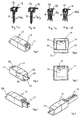
- FIGS 1a-1d show different embodiments of a clamp 10a-10d for which the tool according to the invention is designed for.
- the clamps 10a and 10b are so called TP-clamps, provided with a single nail 11 and a head 12, the head 12 being configured to enclose an electric cable (not shown), the head 12 being provided with an aperture 13.
- Figure 1c and 1d show to different embodiments of a clamp for gypsum or plaster walls, comprising three legs 11, a head 12 with an aperture 13 corresponding to the one for the TP-clamp.
- the purpose of the aperture 13 will be described below in relation to the ram and the ramming pin.
- Figure 2 shows a sleeve shaped housing 14 in perspective with an assembled ramming unit 15.
- the ramming unit 15 is slidably arranged inside an opening 16 extending through the sleeve shaped housing between two extreme positions (see Figures 6 and 7).
- Figure 3 shows a corresponding view in perspective, where the ramming unit 15 is in its second extreme position in the sleeve shaped housing 14, ready for insertion of a clamp (not shown) in the central opening 16.
- the configuration of the sleeve shaped housing 14 and the ramming unit 15, together with the function of the tool, will be described in further details below, referring to the Figures 4-17.
- Figures 4 and 5 show two views of the sleeve shaped housing 14, seen from either side of the housing 14.
- the sleeve shaped housing 14 is at its rear end at the upper side, provided with an elastic lip 18, the outer end of which being provided with a downwards into the opening 16 projecting knob 19.
- the knob 19 is intended to cooperate with a slot in the ramming unit 15 in order to establish the two extreme positions of the ramming unit 15.
- one wall on the sleeve shaped housing 14 extends beyond the remaining three walls, forming a projection 21.
- the projection 21 is provided with two upwards projecting edges 22.
- the length of the projection 21 may preferably be less than the thickness of the electrical wire intended to be fixed to a wall, while the height of the edges 22 may preferably be slightly higher than the thickness of the clamp 10.
- one side wall of the sleeve shaped housing 14 may also be provided with a surface or a tongue 25 intended to project into the opening 16. The tongue 25 will be described in further details below, referring inter alia to Figures 10 and 13.
- Figure 8 shows an assembled tool comprising a sleeve shaped housing 14 and the ramming unit 15.
- one end of the ramming unit 15 is intended to rest against a clamp 10, said end being provided with an attached clamp driver 24 made of metal.
- the purpose of the clamp driver 14 is to rest against the central aperture 13 in the clamp head in order to secure that the ramming force produced by the ramming unit 15 is transferred directly from the ramming unit 15 to the clamp 10 in controlled manner so that the head 12 of the clamp 10 is not unintentionally deformed.
- Figure 9 shows a view of the end of the tool 14 intended to rest against a clamp 10.
- the ramming unit 15 is provided with a ramming clamp driver 24.
- the clamp driver 24 is arranged on the surface of the ramming unit 15 sliding along the extended surface wall 21.
- Figure 10 shows a vertical section through a sleeve shaped housing 14, also showing the opening 16 extending centrally through the housing 16, the extended wall section 21 and the upwards extending side edges 22.
- one of the walls of the sleeve shaped housing 14 is provided with a surface or a tongue 25, which at the end adjacent to the extended surface 21, is pivotably hinged about an axis 26.
- the tongue 25 is intended to partly pivot about the axis 26, so that the tongue 25 partly will swing into the opening 16 extending through the housing 14. In such position, extending into the opening 16 of the housing 14, the tongue 25 will rest against the ramming unit 15.
- the purpose of the tongue 25 is to retain the clamp 10 in the opening 16, so that the clamp does not unintentionally drop out of its seating. Such effect is achieved due to the tongue 25, causing a reduction in the free cross sectional area of the opening 14, whereby the clamp is "wedged" in the opening.
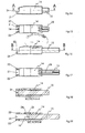
- Figures 11-13 show side views of three of the four sides of the sleeve shaped housing 14.
- the side which is not shown, is the bottom side of the sleeve shaped housing 14.
- the rotational axis 26 of the tongue 25 may preferably be arranged at the outer surface of a wall of the sleeve shaped housing 14.
- the axis 26 may for example be in a form of weakening or attenuation; or may be in form of a partly slot 27 in the wall material.
- Figures 14 and 16 show a side view of the tool according to the invention, where Figure 14 shows the tool with the ramming unit 15 in one extreme position, while Figure 16 shows the same view where the ramming unit 15 is retracted to its opposite extreme position.
- Figures 15 and 17 show a corresponding top view of the tool where the two extreme positions of the ramming piston 15 are illustrated.
- the ramming unit 15 may be moved so far that the tip of the clamp driver 25 just protrude outside the extended wall 21.
- the ramming unit 15 may be retracted so far into the opening 16, that the end of the ramming piston 15 is positioned in the area of the free end of the tongue 25.
- Such features are also illustrated in Figure 19, showing a section seen along the line B-B in Figure 16.
- one side surface of the ramming unit 15 is provided with an elongated slot 28.
- the length and position of the slot 28 in the ramming unit 15 are such that they restrict the total possible distance of movement of the ramming unit 15 inside the opening 16 of the sleeve shaped housing 14.
- the slot 28 cooperates with the knob 19 arranged on the flexible, movable tip 18.
- the ramming unit 15 may preferably have a larger cross sectional area at the end where the clamp driver 24 are arranged, that the remaining part of the ramming unit, the transition between the two different cross sectional areas being even.
- the part of the ramming unit 15 having an increased cross sectional area may extent approximately to the nearest end of the elongated slot 28, preferably a small distance beyond the nearest end.
- two parallel side walls of the sleeve shaped housing 14, at the ramming end 17 of the housing be provided with two constrictions, so that the end of the ramming unit having a reduced cross sectional is resting against said constrictions.
- the tool according to the present invention functions as follows:
Landscapes
- Engineering & Computer Science (AREA)
- Mechanical Engineering (AREA)
- Installation Of Indoor Wiring (AREA)
- Clamps And Clips (AREA)
Applications Claiming Priority (1)
| Application Number | Priority Date | Filing Date | Title |
|---|---|---|---|
| NO20053522A NO323432B1 (no) | 2005-07-18 | 2005-07-18 | Dor for festing av klammer |
Publications (3)
| Publication Number | Publication Date |
|---|---|
| EP1745892A2 true EP1745892A2 (de) | 2007-01-24 |
| EP1745892A3 EP1745892A3 (de) | 2010-06-02 |
| EP1745892B1 EP1745892B1 (de) | 2017-08-30 |
Family
ID=35295504
Family Applications (1)
| Application Number | Title | Priority Date | Filing Date |
|---|---|---|---|
| EP06253708.9A Active EP1745892B1 (de) | 2005-07-18 | 2006-07-14 | Werkzeug zur Befestigung von Klemmen an einer Tragfläche |
Country Status (2)
| Country | Link |
|---|---|
| EP (1) | EP1745892B1 (de) |
| NO (1) | NO323432B1 (de) |
Cited By (1)
| Publication number | Priority date | Publication date | Assignee | Title |
|---|---|---|---|---|
| EP2792453A3 (de) * | 2013-04-17 | 2015-05-27 | Thor Gunnar Pettersen | Mehrfachbehälterspannwerkzeug |
Family Cites Families (6)
| Publication number | Priority date | Publication date | Assignee | Title |
|---|---|---|---|---|
| US2973520A (en) * | 1959-06-16 | 1961-03-07 | Star Prec Devices Inc | Small diameter stud adapter |
| CH388872A (de) * | 1961-10-27 | 1965-02-28 | Beer Hans Dr | Handwerkzeug zum Bereithalten und Eintreiben von zugespitzten Einschlagorganen |
| US3783919A (en) * | 1972-04-25 | 1974-01-08 | Spector G | Glazier{40 s point holder |
| US4062483A (en) * | 1976-04-09 | 1977-12-13 | Brigante Paul J | Window shade hanging device |
| US5934139A (en) * | 1998-05-01 | 1999-08-10 | Tucker; Kevin N. | Bi-directional impact tool |
| DE19938923C2 (de) * | 1999-08-17 | 2001-07-12 | Hubert Chrometz | Vorrichtung zum Einschlagen von Nägeln |
-
2005
- 2005-07-18 NO NO20053522A patent/NO323432B1/no unknown
-
2006
- 2006-07-14 EP EP06253708.9A patent/EP1745892B1/de active Active
Non-Patent Citations (1)
| Title |
|---|
| None |
Cited By (3)
| Publication number | Priority date | Publication date | Assignee | Title |
|---|---|---|---|---|
| EP2792453A3 (de) * | 2013-04-17 | 2015-05-27 | Thor Gunnar Pettersen | Mehrfachbehälterspannwerkzeug |
| EP3345727A1 (de) * | 2013-04-17 | 2018-07-11 | Thor Gunnar Pettersen | Multi-magazin-spannwerkzeug |
| EP3560659A1 (de) * | 2013-04-17 | 2019-10-30 | Thor Gunnar Pettersen | Multi-magazin-spannwerkzeug |
Also Published As
| Publication number | Publication date |
|---|---|
| EP1745892B1 (de) | 2017-08-30 |
| NO20053522L (no) | 2007-01-19 |
| NO323432B1 (no) | 2007-04-30 |
| NO20053522D0 (no) | 2005-07-18 |
| EP1745892A3 (de) | 2010-06-02 |
Similar Documents
| Publication | Publication Date | Title |
|---|---|---|
| CA2444284C (en) | Outlet box for concrete walls | |
| JP4307356B2 (ja) | 自動停止装置付スライドファスナー用スライダー | |
| EP1741518A3 (de) | Nagelmaschine | |
| EP1925404A3 (de) | Werkzeugmaschine | |
| KR20070116879A (ko) | 클립을 장착한 줄자와 이 줄자의 조립방법 | |
| EP1052068A3 (de) | Einfacher kraftgetriebener Hefter | |
| TWI303160B (en) | Slide fastener slider with automatic locking device | |
| KR100298804B1 (ko) | 자동 로크기구를 갖는 슬라이드 파스너 슬라이더 | |
| EP1745892A2 (de) | Werkzeug zur Befestigung von Klemmen an einer Tragfläche | |
| US7549549B1 (en) | Universal low voltage box bracket | |
| KR100766620B1 (ko) | 가구용 힌지의 힌지 암을 고정하기 위한 고정판 | |
| EP2650989A2 (de) | Von Befestigungselement unterstützter Aufhänger | |
| US20030047649A1 (en) | Support element for suspending elongate objects from a ceiling | |
| KR101348290B1 (ko) | 테이프 부착기 | |
| USD529826S1 (en) | Multipurpose tool facilitating formation of accurate bends in electrical conduit | |
| JP4423796B2 (ja) | ステープラー | |
| WO2008096937A1 (en) | The support device of elastic body for orthodontics | |
| JP3664970B2 (ja) | 電動工具 | |
| JP3753268B2 (ja) | メータ用指針引き抜き治具 | |
| GB2060359A (en) | Handle mounting device | |
| JPH08126169A (ja) | ワイヤハーネス用クランプ | |
| ITBO20000288A1 (it) | Giunto per il collegamento rapido e reversibile di due parti di un mobile poste tra loro a squadro . | |
| JP3859993B2 (ja) | 配設体 | |
| KR100619262B1 (ko) | 전방 뽑기부를 가지는 해머와 해머 헤드, 및 표면으로부터 못을 뽑는 방법 | |
| JP2019073940A (ja) | 押さえ具 |
Legal Events
| Date | Code | Title | Description |
|---|---|---|---|
| PUAI | Public reference made under article 153(3) epc to a published international application that has entered the european phase |
Free format text: ORIGINAL CODE: 0009012 |
|
| AK | Designated contracting states |
Kind code of ref document: A2 Designated state(s): AT BE BG CH CY CZ DE DK EE ES FI FR GB GR HU IE IS IT LI LT LU LV MC NL PL PT RO SE SI SK TR |
|
| AX | Request for extension of the european patent |
Extension state: AL BA HR MK YU |
|
| PUAL | Search report despatched |
Free format text: ORIGINAL CODE: 0009013 |
|
| AK | Designated contracting states |
Kind code of ref document: A3 Designated state(s): AT BE BG CH CY CZ DE DK EE ES FI FR GB GR HU IE IS IT LI LT LU LV MC NL PL PT RO SE SI SK TR |
|
| AX | Request for extension of the european patent |
Extension state: AL BA HR MK RS |
|
| 17P | Request for examination filed |
Effective date: 20101119 |
|
| AKX | Designation fees paid |
Designated state(s): AT BE BG CH CY CZ DE DK EE ES FI FR GB GR HU IE IS IT LI LT LU LV MC NL PL PT RO SE SI SK TR |
|
| 17Q | First examination report despatched |
Effective date: 20110223 |
|
| GRAP | Despatch of communication of intention to grant a patent |
Free format text: ORIGINAL CODE: EPIDOSNIGR1 |
|
| STAA | Information on the status of an ep patent application or granted ep patent |
Free format text: STATUS: GRANT OF PATENT IS INTENDED |
|
| INTG | Intention to grant announced |
Effective date: 20170203 |
|
| GRAS | Grant fee paid |
Free format text: ORIGINAL CODE: EPIDOSNIGR3 |
|
| GRAA | (expected) grant |
Free format text: ORIGINAL CODE: 0009210 |
|
| STAA | Information on the status of an ep patent application or granted ep patent |
Free format text: STATUS: THE PATENT HAS BEEN GRANTED |
|
| AK | Designated contracting states |
Kind code of ref document: B1 Designated state(s): AT BE BG CH CY CZ DE DK EE ES FI FR GB GR HU IE IS IT LI LT LU LV MC NL PL PT RO SE SI SK TR |
|
| REG | Reference to a national code |
Ref country code: GB Ref legal event code: FG4D |
|
| REG | Reference to a national code |
Ref country code: CH Ref legal event code: EP |
|
| REG | Reference to a national code |
Ref country code: AT Ref legal event code: REF Ref document number: 923074 Country of ref document: AT Kind code of ref document: T Effective date: 20170915 |
|
| REG | Reference to a national code |
Ref country code: IE Ref legal event code: FG4D |
|
| REG | Reference to a national code |
Ref country code: DE Ref legal event code: R096 Ref document number: 602006053453 Country of ref document: DE |
|
| REG | Reference to a national code |
Ref country code: SE Ref legal event code: TRGR |
|
| REG | Reference to a national code |
Ref country code: NL Ref legal event code: MP Effective date: 20170830 |
|
| REG | Reference to a national code |
Ref country code: LT Ref legal event code: MG4D |
|
| REG | Reference to a national code |
Ref country code: AT Ref legal event code: MK05 Ref document number: 923074 Country of ref document: AT Kind code of ref document: T Effective date: 20170830 |
|
| PG25 | Lapsed in a contracting state [announced via postgrant information from national office to epo] |
Ref country code: AT Free format text: LAPSE BECAUSE OF FAILURE TO SUBMIT A TRANSLATION OF THE DESCRIPTION OR TO PAY THE FEE WITHIN THE PRESCRIBED TIME-LIMIT Effective date: 20170830 Ref country code: LT Free format text: LAPSE BECAUSE OF FAILURE TO SUBMIT A TRANSLATION OF THE DESCRIPTION OR TO PAY THE FEE WITHIN THE PRESCRIBED TIME-LIMIT Effective date: 20170830 |
|
| PG25 | Lapsed in a contracting state [announced via postgrant information from national office to epo] |
Ref country code: BG Free format text: LAPSE BECAUSE OF FAILURE TO SUBMIT A TRANSLATION OF THE DESCRIPTION OR TO PAY THE FEE WITHIN THE PRESCRIBED TIME-LIMIT Effective date: 20171130 Ref country code: GR Free format text: LAPSE BECAUSE OF FAILURE TO SUBMIT A TRANSLATION OF THE DESCRIPTION OR TO PAY THE FEE WITHIN THE PRESCRIBED TIME-LIMIT Effective date: 20171201 Ref country code: IS Free format text: LAPSE BECAUSE OF FAILURE TO SUBMIT A TRANSLATION OF THE DESCRIPTION OR TO PAY THE FEE WITHIN THE PRESCRIBED TIME-LIMIT Effective date: 20171230 Ref country code: ES Free format text: LAPSE BECAUSE OF FAILURE TO SUBMIT A TRANSLATION OF THE DESCRIPTION OR TO PAY THE FEE WITHIN THE PRESCRIBED TIME-LIMIT Effective date: 20170830 Ref country code: LV Free format text: LAPSE BECAUSE OF FAILURE TO SUBMIT A TRANSLATION OF THE DESCRIPTION OR TO PAY THE FEE WITHIN THE PRESCRIBED TIME-LIMIT Effective date: 20170830 |
|
| PG25 | Lapsed in a contracting state [announced via postgrant information from national office to epo] |
Ref country code: NL Free format text: LAPSE BECAUSE OF FAILURE TO SUBMIT A TRANSLATION OF THE DESCRIPTION OR TO PAY THE FEE WITHIN THE PRESCRIBED TIME-LIMIT Effective date: 20170830 |
|
| PG25 | Lapsed in a contracting state [announced via postgrant information from national office to epo] |
Ref country code: CZ Free format text: LAPSE BECAUSE OF FAILURE TO SUBMIT A TRANSLATION OF THE DESCRIPTION OR TO PAY THE FEE WITHIN THE PRESCRIBED TIME-LIMIT Effective date: 20170830 Ref country code: PL Free format text: LAPSE BECAUSE OF FAILURE TO SUBMIT A TRANSLATION OF THE DESCRIPTION OR TO PAY THE FEE WITHIN THE PRESCRIBED TIME-LIMIT Effective date: 20170830 Ref country code: DK Free format text: LAPSE BECAUSE OF FAILURE TO SUBMIT A TRANSLATION OF THE DESCRIPTION OR TO PAY THE FEE WITHIN THE PRESCRIBED TIME-LIMIT Effective date: 20170830 Ref country code: RO Free format text: LAPSE BECAUSE OF FAILURE TO SUBMIT A TRANSLATION OF THE DESCRIPTION OR TO PAY THE FEE WITHIN THE PRESCRIBED TIME-LIMIT Effective date: 20170830 |
|
| PG25 | Lapsed in a contracting state [announced via postgrant information from national office to epo] |
Ref country code: IT Free format text: LAPSE BECAUSE OF FAILURE TO SUBMIT A TRANSLATION OF THE DESCRIPTION OR TO PAY THE FEE WITHIN THE PRESCRIBED TIME-LIMIT Effective date: 20170830 Ref country code: EE Free format text: LAPSE BECAUSE OF FAILURE TO SUBMIT A TRANSLATION OF THE DESCRIPTION OR TO PAY THE FEE WITHIN THE PRESCRIBED TIME-LIMIT Effective date: 20170830 Ref country code: SK Free format text: LAPSE BECAUSE OF FAILURE TO SUBMIT A TRANSLATION OF THE DESCRIPTION OR TO PAY THE FEE WITHIN THE PRESCRIBED TIME-LIMIT Effective date: 20170830 |
|
| REG | Reference to a national code |
Ref country code: DE Ref legal event code: R097 Ref document number: 602006053453 Country of ref document: DE |
|
| PLBE | No opposition filed within time limit |
Free format text: ORIGINAL CODE: 0009261 |
|
| STAA | Information on the status of an ep patent application or granted ep patent |
Free format text: STATUS: NO OPPOSITION FILED WITHIN TIME LIMIT |
|
| 26N | No opposition filed |
Effective date: 20180531 |
|
| PG25 | Lapsed in a contracting state [announced via postgrant information from national office to epo] |
Ref country code: SI Free format text: LAPSE BECAUSE OF FAILURE TO SUBMIT A TRANSLATION OF THE DESCRIPTION OR TO PAY THE FEE WITHIN THE PRESCRIBED TIME-LIMIT Effective date: 20170830 |
|
| REG | Reference to a national code |
Ref country code: DE Ref legal event code: R119 Ref document number: 602006053453 Country of ref document: DE |
|
| REG | Reference to a national code |
Ref country code: CH Ref legal event code: PL |
|
| GBPC | Gb: european patent ceased through non-payment of renewal fee |
Effective date: 20180714 |
|
| PG25 | Lapsed in a contracting state [announced via postgrant information from national office to epo] |
Ref country code: LU Free format text: LAPSE BECAUSE OF NON-PAYMENT OF DUE FEES Effective date: 20180714 Ref country code: MC Free format text: LAPSE BECAUSE OF FAILURE TO SUBMIT A TRANSLATION OF THE DESCRIPTION OR TO PAY THE FEE WITHIN THE PRESCRIBED TIME-LIMIT Effective date: 20170830 |
|
| REG | Reference to a national code |
Ref country code: BE Ref legal event code: MM Effective date: 20180731 |
|
| REG | Reference to a national code |
Ref country code: IE Ref legal event code: MM4A |
|
| PG25 | Lapsed in a contracting state [announced via postgrant information from national office to epo] |
Ref country code: CH Free format text: LAPSE BECAUSE OF NON-PAYMENT OF DUE FEES Effective date: 20180731 Ref country code: GB Free format text: LAPSE BECAUSE OF NON-PAYMENT OF DUE FEES Effective date: 20180714 Ref country code: FR Free format text: LAPSE BECAUSE OF NON-PAYMENT OF DUE FEES Effective date: 20180731 Ref country code: LI Free format text: LAPSE BECAUSE OF NON-PAYMENT OF DUE FEES Effective date: 20180731 Ref country code: IE Free format text: LAPSE BECAUSE OF NON-PAYMENT OF DUE FEES Effective date: 20180714 Ref country code: DE Free format text: LAPSE BECAUSE OF NON-PAYMENT OF DUE FEES Effective date: 20190201 |
|
| PG25 | Lapsed in a contracting state [announced via postgrant information from national office to epo] |
Ref country code: BE Free format text: LAPSE BECAUSE OF NON-PAYMENT OF DUE FEES Effective date: 20180731 |
|
| PG25 | Lapsed in a contracting state [announced via postgrant information from national office to epo] |
Ref country code: TR Free format text: LAPSE BECAUSE OF FAILURE TO SUBMIT A TRANSLATION OF THE DESCRIPTION OR TO PAY THE FEE WITHIN THE PRESCRIBED TIME-LIMIT Effective date: 20170830 |
|
| PG25 | Lapsed in a contracting state [announced via postgrant information from national office to epo] |
Ref country code: PT Free format text: LAPSE BECAUSE OF FAILURE TO SUBMIT A TRANSLATION OF THE DESCRIPTION OR TO PAY THE FEE WITHIN THE PRESCRIBED TIME-LIMIT Effective date: 20170830 Ref country code: HU Free format text: LAPSE BECAUSE OF FAILURE TO SUBMIT A TRANSLATION OF THE DESCRIPTION OR TO PAY THE FEE WITHIN THE PRESCRIBED TIME-LIMIT; INVALID AB INITIO Effective date: 20060714 |
|
| PG25 | Lapsed in a contracting state [announced via postgrant information from national office to epo] |
Ref country code: CY Free format text: LAPSE BECAUSE OF FAILURE TO SUBMIT A TRANSLATION OF THE DESCRIPTION OR TO PAY THE FEE WITHIN THE PRESCRIBED TIME-LIMIT Effective date: 20170830 |
|
| P01 | Opt-out of the competence of the unified patent court (upc) registered |
Effective date: 20230330 |
|
| PGFP | Annual fee paid to national office [announced via postgrant information from national office to epo] |
Ref country code: FI Payment date: 20250620 Year of fee payment: 20 |
|
| PGFP | Annual fee paid to national office [announced via postgrant information from national office to epo] |
Ref country code: SE Payment date: 20250619 Year of fee payment: 20 |