EP1746005A1 - Procédé et dispositif pour informer le conducteur d'un véhicule automobile - Google Patents
Procédé et dispositif pour informer le conducteur d'un véhicule automobile Download PDFInfo
- Publication number
- EP1746005A1 EP1746005A1 EP06115653A EP06115653A EP1746005A1 EP 1746005 A1 EP1746005 A1 EP 1746005A1 EP 06115653 A EP06115653 A EP 06115653A EP 06115653 A EP06115653 A EP 06115653A EP 1746005 A1 EP1746005 A1 EP 1746005A1
- Authority
- EP
- European Patent Office
- Prior art keywords
- distance
- driver
- value
- distance value
- delay
- Prior art date
- Legal status (The legal status is an assumption and is not a legal conclusion. Google has not performed a legal analysis and makes no representation as to the accuracy of the status listed.)
- Withdrawn
Links
Images
Classifications
-
- B—PERFORMING OPERATIONS; TRANSPORTING
- B60—VEHICLES IN GENERAL
- B60W—CONJOINT CONTROL OF VEHICLE SUB-UNITS OF DIFFERENT TYPE OR DIFFERENT FUNCTION; CONTROL SYSTEMS SPECIALLY ADAPTED FOR HYBRID VEHICLES; ROAD VEHICLE DRIVE CONTROL SYSTEMS FOR PURPOSES NOT RELATED TO THE CONTROL OF A PARTICULAR SUB-UNIT
- B60W30/00—Purposes of road vehicle drive control systems not related to the control of a particular sub-unit, e.g. of systems using conjoint control of vehicle sub-units
- B60W30/14—Adaptive cruise control
- B60W30/16—Control of distance between vehicles, e.g. keeping a distance to preceding vehicle
-
- B—PERFORMING OPERATIONS; TRANSPORTING
- B60—VEHICLES IN GENERAL
- B60W—CONJOINT CONTROL OF VEHICLE SUB-UNITS OF DIFFERENT TYPE OR DIFFERENT FUNCTION; CONTROL SYSTEMS SPECIALLY ADAPTED FOR HYBRID VEHICLES; ROAD VEHICLE DRIVE CONTROL SYSTEMS FOR PURPOSES NOT RELATED TO THE CONTROL OF A PARTICULAR SUB-UNIT
- B60W50/00—Details of control systems for road vehicle drive control not related to the control of a particular sub-unit, e.g. process diagnostic or vehicle driver interfaces
- B60W50/08—Interaction between the driver and the control system
- B60W50/14—Means for informing the driver, warning the driver or prompting a driver intervention
Definitions
- the present invention relates to a method and a device for informing the driver of a motor vehicle, which is equipped with a distance sensing device and an adaptive distance and speed controller, in which a takeover request is activated, which notifies the driver that a critical approach to a target object takes place ,
- An adaptive cruise control takeover request is issued to prompt the driver in a situation beyond the control of the system to manually take control of the vehicle.
- the English translation of Adaptive Cruise Control is adaptive cruise control, abbreviated ACC.
- ACC adaptive cruise control
- the delay is determined which is necessary to reduce the relative speed to an on-vehicle vehicle before a collision would occur with that vehicle. If the system can not reach the specified delay, a takeover request must be issued.
- application parameters are essentially the minimum distance between own vehicle and other vehicle, outside of which the relative speed is to be reduced, and an acceleration offset, which adds to the maximum possible delay of the system is the threshold for the Takeover request available.
- From the DE 102 31 687 A1 is also known such a method and a corresponding device.
- a distance to the other vehicle is defined, below which a takeover request is issued.
- the invention is therefore based on the object to provide an improved method and a corresponding device thereto.
- a takeover request is to be presented which warns based on the driver's sensations precisely in the situations in which intervention by the driver beyond ordinary driving tasks with ACC becomes necessary.
- Common driving tasks include the steering of the vehicle, turn signals, observation of other traffic and so on.
- the invention is characterized by the following method steps: a distance value for a distance between the motor vehicle and a target object is determined, a first route value for a driver reaction time is determined, a second distance value for a deceleration is determined, an expected distance value is determined from the distance value and the distance values, the prospective distance value is compared with a threshold value, and if the prospective distance value falls below the threshold value, the transfer request device is activated.
- a distance value for a distance between the motor vehicle and a target object can be determined, in the adaptive distance and speed controller of the device is a first distance value for a driver reaction time, a second distance value for a delay, from the distance value and the distance values a probable distance value can be determined and the probable distance value can be compared to a threshold value, and the transfer request device of the device can be activated if the distance value falls below the threshold value.
- the gist of the invention is based on activating the takeover request in response to a driver response time and a delay. It is then warned if to avoid a collision by the driver braking with a delay, also referred to as a minimum delay, must be initiated. It also takes into account that the driver needs a response time to begin this braking.
- the reaction time of the driver as well as the minimum deceleration to be achieved by the driver are provided here as application parameters.
- the driver expects a takeover request if the current driving situation requires immediate intervention by the driver. If the system detects a situation that can not be mastered by the system but in which intervention by the driver is sufficient at a later point in time, then no takeover request is yet to be issued.
- the intervention of the driver may be by initiating a braking or done by an evasive maneuver. Since the ACC system can not detect whether an evasive maneuver is possible and an evasive maneuver can be initiated later in critical situations than a braking maneuver, a warning should be given due to a necessary braking. A typical braking process is defined. If this defined braking process is not sufficient to avoid a collision, a warning should be issued. This ensures that driver intervention beyond an ordinary level is required. This means that the driver has to pay full attention to the traffic again.
- the delay depends on the speed of the vehicle.
- the deceleration remains constant during the braking process.
- the speed that is used during the time of detection is taken as a basis. At higher speeds, braked more.
- a time-dependent braking process is defined instead of braking with a constant deceleration. As time goes on, the negative acceleration gets bigger. The reaction time can be integrated in this case in this process.
- the braking course is dependent both on the speed of the own vehicle and time-dependent.
- a threshold and thus a safety distance is adjustable.
- a warning is already issued if the defined braking process is not sufficient to reduce the relative speed within a safety distance to the vehicle in front.
- the current relative speed and acceleration can also be assumed, and a maximum possible change in the acceleration of the other vehicle can be defined. This in turn results in the uncertainty range of the position of the other vehicle within which the vehicle may be located in the future. Entering this area leads to a warning.
- the driver takeover request can be adapted to different behavioral requirements with a few parameters.
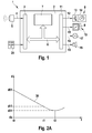
- FIG. 1 shows a device 1 with a distance and speed controller 2, which has an input circuit 3.
- a distance sensing device such as a radar or Lidarsensor 5
- the radar or lidar sensor 5 emits radar or laser radiation, which is reflected in part on objects. Reflected radiation is received by the radar or lidar sensor 5. In the case of a radar sensor, the radar radiation may have FMCW modulation or pulse modulation.
- the radar or Lidarsensor 5 generates output signals from measured received signals, which are supplied to the distance and speed controller 2 as input signals. These signals include magnitudes d of the objects as well as relative velocities Vrel of the objects with respect to the distance and speed controlled vehicle.
- the objects are also referred to as target objects or third-party vehicles. These quantities are supplied to the input circuit 3 and forwarded to a processing device 7 by means of a data exchange system 6, which may be, for example, a CAN bus.
- This processing device 7 may be, for example, a microprocessor or a signal processor in which variables and control variables are formed from the variables measured by the sensor 5.
- the processing device 7 determines from the relative position of the objects detected by the sensor 5 as well as their distance d and their relative speed Vrel at least one target object, which is of particular relevance for the distance and speed control, since this target object influences the output variables in a particular degree.
- the processing device 7 generates control signals for a deceleration device 8 of the vehicle, control signals for a performance-determining actuator 9 of a vehicle drive unit 10, which can be configured, for example, as a throttle actuator 9 or as a fuel injection pump 9, and signals for activating or deactivating a takeover request for the driver of the vehicle ,
- These output signals generated by the processing device 7 are output to an output circuit 11 by means of the data exchange system 6.
- a delay signal is output via an electrically conductive connection 12 to the delay device 8 of the vehicle.
- This delay signal is usually supplied to a brake drive device 13 which actuates brakes 14 of the vehicle in accordance with the deceleration signal.
- an acceleration signal which is the power-determining actuator 9 of the vehicle drive unit 10 is supplied.
- the vehicle drive unit 10 is influenced in a corresponding manner according to the controller output variables.
- a takeover request signal can be output to an electrically conductive connection 16 via the output circuit 11, which is supplied to an optical takeover request device 17.
- This optical takeover requesting device 17 consists, for example, of a light source in the driver's field of vision or of a plain text display which is mounted in the driver's field of vision and visually signals to the driver that the delay capability is insufficient to permit a critical approach of the own vehicle to a target object prevent.
- the output circuit 11 may output a further strobe request signal via an electrically conductive connection 18 to an acoustic handover requestor 19.
- This acoustic takeover request device 19 can be, for example, a buzzer or a ringtone in the vehicle interior, or it can be a voice output device that prompts the driver for a delay intervention.
- values for a desired driving speed can be entered by the driver and a comfort program can be set which permits sporty or relaxed driving.
- the distance and speed controller 2 is often designed as a comfort system and the deceleration dynamics that the distance and speed controller 2 can control is often limited to 2 to 3 m / sec 2 . It is assumed that the delay capability of the system is limited to a maximum of 3 m / sec 2 .
- a second deceleration capability is motor vehicle and driver dependent. It is determined experimentally and corresponds to a braking behavior of an average driver. It is therefore also referred to as medium delay. This can be designed as a constant or time-dependent.
- the absolute value of a mean deceleration is above the absolute value of 3 m / sec 2 and below the absolute value of full braking.
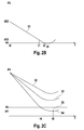
- FIG. 2A shows a graph with a graph 30, in which the distance between two vehicles is plotted over time.
- a first period of time defined by times t0 and t1 describes a reaction time of the driver. During this period, the other vehicle and the own vehicle approach each other by a distance d01-d11.
- a second period of time defined by times t1 and t3, describes an average deceleration in which the vehicle decelerates smoothly. At time t3, the two vehicles are closest, then they move away from each other again. The time t3 determines a culmination point.
- FIG. 2B shows a graph with a graph 31, in which the distance between two vehicles over time for a critical approach is plotted.
- the first time period defined by times t0 and t1
- the second period of time defined by times t1 and t3, also describes the average deceleration in which the vehicle decelerates smoothly.
- the time t3 describes a culmination point.
- the first two summands describe the distance between the two vehicles after the reaction time
- the third and the fourth summand describe the distance traveled during braking.
- a warning is issued when a safe distance is undershot, in particular when a collision can not be avoided if dmin is less than or equal to zero.
- the adjustable safety distance then forms the threshold, which must not be less than or should.
- the safety distance ds can also be set to zero.
- the approximation of the two vehicles is described by means of the two defined values, namely the reaction time treak and the mean delay ⁇ FZG, also referred to as application parameters.
- FIG. 2C shows a graph with graphs 32, 33 and 34.
- a constant ds is entered on the ordinate, which defines a safety distance.
- the graph 34 describes the distance between two vehicles, which are expected to approach a future time t4 to a safety distance of ds. Because the safety distance from ds is to be maintained, a warning is issued. A maximum approximation is given at a culmination point 35 at time t5 with a distance of dK.
Landscapes
- Engineering & Computer Science (AREA)
- Automation & Control Theory (AREA)
- Transportation (AREA)
- Mechanical Engineering (AREA)
- Human Computer Interaction (AREA)
- Control Of Driving Devices And Active Controlling Of Vehicle (AREA)
- Traffic Control Systems (AREA)
Applications Claiming Priority (1)
| Application Number | Priority Date | Filing Date | Title |
|---|---|---|---|
| DE102005033522A DE102005033522A1 (de) | 2005-07-18 | 2005-07-18 | Verfahren und Vorrichtung zur Benachrichtigung des Fahrers eines Kraftfahrzeugs |
Publications (1)
| Publication Number | Publication Date |
|---|---|
| EP1746005A1 true EP1746005A1 (fr) | 2007-01-24 |
Family
ID=36869854
Family Applications (1)
| Application Number | Title | Priority Date | Filing Date |
|---|---|---|---|
| EP06115653A Withdrawn EP1746005A1 (fr) | 2005-07-18 | 2006-06-19 | Procédé et dispositif pour informer le conducteur d'un véhicule automobile |
Country Status (2)
| Country | Link |
|---|---|
| EP (1) | EP1746005A1 (fr) |
| DE (1) | DE102005033522A1 (fr) |
Families Citing this family (1)
| Publication number | Priority date | Publication date | Assignee | Title |
|---|---|---|---|---|
| DE102013225906A1 (de) * | 2013-12-13 | 2015-06-18 | Volkswagen Aktiengesellschaft | Kraftfahrzeug mit Kollisionswarnung |
Citations (6)
| Publication number | Priority date | Publication date | Assignee | Title |
|---|---|---|---|---|
| US5014200A (en) * | 1990-02-20 | 1991-05-07 | General Motors Corporation | Adaptive cruise system |
| US5684473A (en) * | 1994-03-25 | 1997-11-04 | Nippondenso Co., Ltd. | Measuring apparatus for detecting distance between vehicles and related warning system |
| DE10015299A1 (de) | 2000-03-28 | 2001-10-04 | Bosch Gmbh Robert | Verfahren und Vorrichtung zur Auslösung einer Übernahmeaufforderung für ACC-gesteuerte Fahrzeuge |
| FR2841518A1 (fr) * | 2002-06-27 | 2004-01-02 | Peugeot Citroen Automobiles Sa | Procede et systeme d'aide a la conduite d'un vehicule automobile |
| DE10231687A1 (de) | 2002-07-10 | 2004-01-22 | Robert Bosch Gmbh | Verfahren und Vorrichtung zur Benachtichtigung des Fahrers eines Kraftfahrzeugs |
| DE10335689A1 (de) * | 2002-08-01 | 2004-02-26 | Visteon Global Technologies, Inc., Dearborn | Fahreralarmsystem für Fahrzeuge mit adaptivem Geschwindigkeitsregelsystem |
-
2005
- 2005-07-18 DE DE102005033522A patent/DE102005033522A1/de not_active Withdrawn
-
2006
- 2006-06-19 EP EP06115653A patent/EP1746005A1/fr not_active Withdrawn
Patent Citations (6)
| Publication number | Priority date | Publication date | Assignee | Title |
|---|---|---|---|---|
| US5014200A (en) * | 1990-02-20 | 1991-05-07 | General Motors Corporation | Adaptive cruise system |
| US5684473A (en) * | 1994-03-25 | 1997-11-04 | Nippondenso Co., Ltd. | Measuring apparatus for detecting distance between vehicles and related warning system |
| DE10015299A1 (de) | 2000-03-28 | 2001-10-04 | Bosch Gmbh Robert | Verfahren und Vorrichtung zur Auslösung einer Übernahmeaufforderung für ACC-gesteuerte Fahrzeuge |
| FR2841518A1 (fr) * | 2002-06-27 | 2004-01-02 | Peugeot Citroen Automobiles Sa | Procede et systeme d'aide a la conduite d'un vehicule automobile |
| DE10231687A1 (de) | 2002-07-10 | 2004-01-22 | Robert Bosch Gmbh | Verfahren und Vorrichtung zur Benachtichtigung des Fahrers eines Kraftfahrzeugs |
| DE10335689A1 (de) * | 2002-08-01 | 2004-02-26 | Visteon Global Technologies, Inc., Dearborn | Fahreralarmsystem für Fahrzeuge mit adaptivem Geschwindigkeitsregelsystem |
Also Published As
| Publication number | Publication date |
|---|---|
| DE102005033522A1 (de) | 2007-01-25 |
Similar Documents
| Publication | Publication Date | Title |
|---|---|---|
| EP3153376B1 (fr) | Procédé et dispositif pour déterminer le temps de réaction adaptatif du conducteur d'un véhicule automobile | |
| DE112016002750B4 (de) | Fahrzeugsteuerungsvorrichtung und fahrzeugsteuerungsverfahren | |
| EP1521686B1 (fr) | Procede et dispositif permettant d'informer le conducteur d'un vehicule automobile | |
| DE102004008888B4 (de) | Fahrzeug-Steuersystem | |
| DE102009010006B4 (de) | Verfahren und Vorrichtung zum teilautonomen oder autonomen Fahren eines Kraftfahrzeugs | |
| EP1900589B1 (fr) | Système d'assistance à la conduite doté d'une fonction d'avertissement | |
| DE19514654B4 (de) | Kollisionsalarmsystem für ein Kraftfahrzeug | |
| DE102007039039B4 (de) | Ansteuerung von Sicherheitsmitteln eines Kraftfahrzeugs | |
| DE102016101194A1 (de) | Fahrzeugbremssteuervorrichtung | |
| DE102010049351A1 (de) | Verfahren zum Betreiben einer Bremsassistenzvorrichtung und Bremsassistenzvorrichtung für ein Fahrzeug | |
| DE102015122603A1 (de) | Fortschrittliches Fahrerassistenzsystem für Fahrzeuge | |
| EP3625092B1 (fr) | Procédé de détermination d'un freinage d'urgence autonome, procédé d'exécution du freinage d'urgence, et dispositif de commande pour un système de dynamique de translation | |
| DE102013102087A1 (de) | Verfahren zum Betrieb eines Fahrerassistenzsystems eines Fahrzeugs | |
| DE102015001971A1 (de) | Verfahren und Überwachungsvorrichtung zur Überwachung von Fahrerassistenzsystemen | |
| DE102010008208A1 (de) | Verfahren zur Verhinderung von Kollisionen oder Verminderung einer Kollisionsstärke eines Fahrzeugs | |
| EP3475131B1 (fr) | Système de freinage d'urgence pour un véhicule ainsi que procédé de commande du système de freinage d'urgence | |
| EP1665198B1 (fr) | Procede et dispositif d'emission d'une alerte | |
| DE102019108502A1 (de) | Verfahren und Steuervorrichtung zur Steuerung eines selbsttätigen Notbremssystems | |
| DE102005014803A1 (de) | Verfahren und Vorrichtung zum Steuern eines Kollisionsvermeidungssystems | |
| EP2054281B1 (fr) | Commande de moyens de sécurité d'un véhicule automobile | |
| WO2006087282A1 (fr) | Procede pour detecter un processus de depassement imminent | |
| DE102012202481A1 (de) | Verfahren für ein Assistenzsystem eines Fahrzeugs | |
| DE102019122249B4 (de) | Verfahren zum Ermitteln eines Fahrspurwechsels, Fahrassistenzsystem und Fahrzeug | |
| EP1426906A1 (fr) | Strategie d' alerte pendant l'identification de voie de circulation par un véhicule | |
| EP1746005A1 (fr) | Procédé et dispositif pour informer le conducteur d'un véhicule automobile |
Legal Events
| Date | Code | Title | Description |
|---|---|---|---|
| PUAI | Public reference made under article 153(3) epc to a published international application that has entered the european phase |
Free format text: ORIGINAL CODE: 0009012 |
|
| AK | Designated contracting states |
Kind code of ref document: A1 Designated state(s): AT BE BG CH CY CZ DE DK EE ES FI FR GB GR HU IE IS IT LI LT LU LV MC NL PL PT RO SE SI SK TR |
|
| AX | Request for extension of the european patent |
Extension state: AL BA HR MK YU |
|
| 17P | Request for examination filed |
Effective date: 20070724 |
|
| AKX | Designation fees paid |
Designated state(s): DE FR GB IT |
|
| 17Q | First examination report despatched |
Effective date: 20070919 |
|
| STAA | Information on the status of an ep patent application or granted ep patent |
Free format text: STATUS: THE APPLICATION IS DEEMED TO BE WITHDRAWN |
|
| 18D | Application deemed to be withdrawn |
Effective date: 20080401 |