EP1746234A2 - Ferrure pour cloison repliable et coulissante - Google Patents
Ferrure pour cloison repliable et coulissante Download PDFInfo
- Publication number
- EP1746234A2 EP1746234A2 EP06011157A EP06011157A EP1746234A2 EP 1746234 A2 EP1746234 A2 EP 1746234A2 EP 06011157 A EP06011157 A EP 06011157A EP 06011157 A EP06011157 A EP 06011157A EP 1746234 A2 EP1746234 A2 EP 1746234A2
- Authority
- EP
- European Patent Office
- Prior art keywords
- fitting
- frame
- individual elements
- sliding wall
- folding
- Prior art date
- Legal status (The legal status is an assumption and is not a legal conclusion. Google has not performed a legal analysis and makes no representation as to the accuracy of the status listed.)
- Withdrawn
Links
- 239000011521 glass Substances 0.000 description 7
- 238000007789 sealing Methods 0.000 description 3
- XAGFODPZIPBFFR-UHFFFAOYSA-N aluminium Chemical compound [Al] XAGFODPZIPBFFR-UHFFFAOYSA-N 0.000 description 2
- 229910052782 aluminium Inorganic materials 0.000 description 2
- 238000009434 installation Methods 0.000 description 2
- 239000003570 air Substances 0.000 description 1
- 238000005266 casting Methods 0.000 description 1
- 238000003780 insertion Methods 0.000 description 1
- 230000037431 insertion Effects 0.000 description 1
- 239000000463 material Substances 0.000 description 1
- 239000000779 smoke Substances 0.000 description 1
- XLYOFNOQVPJJNP-UHFFFAOYSA-N water Substances O XLYOFNOQVPJJNP-UHFFFAOYSA-N 0.000 description 1
Images


Classifications
-
- E—FIXED CONSTRUCTIONS
- E05—LOCKS; KEYS; WINDOW OR DOOR FITTINGS; SAFES
- E05D—HINGES OR SUSPENSION DEVICES FOR DOORS, WINDOWS OR WINGS
- E05D15/00—Suspension arrangements for wings
- E05D15/26—Suspension arrangements for wings for folding wings
- E05D15/262—Suspension arrangements for wings for folding wings folding vertically
-
- E—FIXED CONSTRUCTIONS
- E05—LOCKS; KEYS; WINDOW OR DOOR FITTINGS; SAFES
- E05Y—INDEXING SCHEME ASSOCIATED WITH SUBCLASSES E05D AND E05F, RELATING TO CONSTRUCTION ELEMENTS, ELECTRIC CONTROL, POWER SUPPLY, POWER SIGNAL OR TRANSMISSION, USER INTERFACES, MOUNTING OR COUPLING, DETAILS, ACCESSORIES, AUXILIARY OPERATIONS NOT OTHERWISE PROVIDED FOR, APPLICATION THEREOF
- E05Y2800/00—Details, accessories and auxiliary operations not otherwise provided for
- E05Y2800/26—Form or shape
-
- E—FIXED CONSTRUCTIONS
- E05—LOCKS; KEYS; WINDOW OR DOOR FITTINGS; SAFES
- E05Y—INDEXING SCHEME ASSOCIATED WITH SUBCLASSES E05D AND E05F, RELATING TO CONSTRUCTION ELEMENTS, ELECTRIC CONTROL, POWER SUPPLY, POWER SIGNAL OR TRANSMISSION, USER INTERFACES, MOUNTING OR COUPLING, DETAILS, ACCESSORIES, AUXILIARY OPERATIONS NOT OTHERWISE PROVIDED FOR, APPLICATION THEREOF
- E05Y2900/00—Application of doors, windows, wings or fittings thereof
- E05Y2900/10—Application of doors, windows, wings or fittings thereof for buildings or parts thereof
- E05Y2900/13—Type of wing
- E05Y2900/132—Doors
Definitions
- the invention relates to a folding sliding wall consisting of at least one individual element and / or a plurality of individual elements, which may be hinged together by hinges, and in a frame consisting of at least one bottom rail and a ceiling rail, is arranged, wherein the single element or the connected individual elements can be moved laterally in the frame and each individual element consists of a frame with a filling and the frame of the individual elements are coupled via fittings with carriage in the bottom rail and / or ceiling rail.
- Folding sliding wall is understood to mean designs such as horizontal sliding wall, sliding rotary element and sliding elements in the area of the individual elements relative to one another or to the vertical frame, the enumeration not being conclusive.
- folding sliding walls are known in various designs and for different purposes.
- a conservatory is provided with a folding sliding wall whose individual elements consist of a wooden and / or aluminum frame with an inserted glass pane as a filling.
- Another embodiment provides for dividing a large room by a folding sliding wall into two smaller rooms. This is done in the frame a single element, for example, a wooden board or a plasterboard used as a filling to prevent viewing.
- the support of the individual elements takes place on the arranged in the bottom rail carriage.
- the carriage preferably on the vertical center axis on a hole into which a bolt is inserted, which is connected to a fitting.
- a known fitting overlaps and engages under a hinge projecting from the frame.
- the known fitting is C-shaped and extends the hinges for insertion of a continuous retaining pin.
- One end of the C - shaped fitting is shaped so that it can receive the bolt arranged in the carriage. This shape is modeled, for example, a quarter circle.
- the C - shaped, known fitting is attached to the hinges, which are frictionally connected to the carriages in the bottom rail and the ceiling rail. This requires, inter alia, longer retaining pins which take into account the entire length of the C-shaped fitting. Because the C - shaped fitting outside On the frame, that is attached to the visible side, the usual, symmetrical overall view changes. Further, the above-mentioned shape of the fitting end, the seal is interrupted at the end faces of the frame, whereby an ingress of air, water, smoke, etc. in the respective space is made possible at this point.
- the known design of the fitting is therefore voluminous and heavy, since the weight of the individual elements are passed over the outwardly standing on the C - shaped fitting and of this on the bolt in the carriage. The weight thus causes in this embodiment, a moment to be taken into account.
- the invention is therefore based on the object to improve the known fitting so that the above-mentioned disadvantages are avoided, reduces the use of materials and the assembly is simplified.
- An embodiment of the fitting on the side opposite the pin to form a bent U-profile creates a guide element that can be displaced on a rail which is formed on the end faces of the frames of the individual elements or is mounted separately. Such an embodiment facilitates the installation of a folding sliding wall.
- the fitting is executed in a preferred embodiment as a casting.
- a training as a punched - bent part is also possible.
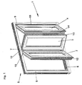
- a folding - sliding wall 1 which consists of three individual elements 2, 3, 4.
- the folding sliding wall 1 is surrounded by a frame 5, which is formed from a bottom rail 6, a ceiling rail 7, a left post 8 and a right post 9.
- the individual elements 2, 3, 4 are connected by hinges (not shown) hinged together.
- the end walls 12, 13 and 15 can move freely in space.
- FIG. 2 The arrangement and attachment of a fitting 16 according to the invention is shown in Figure 2, wherein a carriage 17 is arranged movable in a bottom rail 6.
- the carriage 17 and the fitting 16 are connected by a bolt 18 force and / or form-fitting manner.
- the individual elements 3, 4 are hinged together, for example, by a hinge 19.
- the fastening of the fitting 16 takes place for example by screws.
- FIG 3 is a sectional view of the cross section of the individual elements 3, 4 can be seen.
- the filling 20 consists for example of a double glass pane.
- the frame 21 is made of extruded aluminum profiles having a plurality of chambers with different cross sections.
- 15 sealing strips 22 are fixed in the edge or corner area, which consist of only one hollow chamber in the region of the fitting 16.
- the corners 23 of the fitting 16 are U-shaped and can thus be plugged and fastened on a special rail 24 of the frame 21.
- the attachment is done for example by screwing, but there is also the possibility of a clamp connection.
- the fitting 16 is, as shown in Figure 4, carried out in width so that at least one hollow chamber of the sealing strip 22 is completely formed on the end face 11. A gap is thus avoided. Furthermore, the fitting 16 is attached to the lowermost end 25 of the frame 21 and can transmit the weight of the one or more individual elements 2, 3, 4 directly to the carriage 17 and the bottom rail 6 via the bolt 18.
- the fitting 16 Due to the inventive design of the fitting 16 is made possible that the installation is performed by only person.
- the fitting 16 can be moved, for example, on the rail 24.
- the weight acts vertically downwards while in the known C - shaped design a moment occurs which makes it necessary to align the individual elements in several directions during assembly.
Landscapes
- Engineering & Computer Science (AREA)
- Mechanical Engineering (AREA)
- Extensible Doors And Revolving Doors (AREA)
- Support Devices For Sliding Doors (AREA)
Applications Claiming Priority (1)
| Application Number | Priority Date | Filing Date | Title |
|---|---|---|---|
| DE102005025821A DE102005025821A1 (de) | 2005-06-02 | 2005-06-02 | Beschlag für Falt-Schiebewand |
Publications (2)
| Publication Number | Publication Date |
|---|---|
| EP1746234A2 true EP1746234A2 (fr) | 2007-01-24 |
| EP1746234A3 EP1746234A3 (fr) | 2009-10-28 |
Family
ID=36851385
Family Applications (1)
| Application Number | Title | Priority Date | Filing Date |
|---|---|---|---|
| EP06011157A Withdrawn EP1746234A3 (fr) | 2005-06-02 | 2006-05-31 | Ferrure pour cloison repliable et coulissante |
Country Status (3)
| Country | Link |
|---|---|
| US (1) | US20070029057A1 (fr) |
| EP (1) | EP1746234A3 (fr) |
| DE (1) | DE102005025821A1 (fr) |
Cited By (2)
| Publication number | Priority date | Publication date | Assignee | Title |
|---|---|---|---|---|
| US11098514B2 (en) | 2018-12-20 | 2021-08-24 | Pgt Innovations, Inc. | Sliding door system with mono-track assemblies |
| US11098511B2 (en) | 2018-12-20 | 2021-08-24 | Pgt Innovations, Inc. | Sliding door system with dual track assemblies |
Families Citing this family (5)
| Publication number | Priority date | Publication date | Assignee | Title |
|---|---|---|---|---|
| DE102005007691B3 (de) * | 2005-02-18 | 2006-11-16 | Uhlmann Pac-Systeme Gmbh & Co Kg | Maschinengehäuse für eine Arbeitsmaschine |
| DE102005025817A1 (de) * | 2005-06-02 | 2007-01-04 | Sunflex Aluminiumsysteme Gmbh | Schwenk-Beschlag für Falt-Schiebewand |
| DE202013000348U1 (de) * | 2013-01-14 | 2014-05-08 | Frener & Reifer Gmbh/Srl | Drehlager für Schiebetür- oder Schiebefensteranordnungen |
| DE102017100644B4 (de) * | 2017-01-13 | 2018-08-30 | Solarlux Gmbh | Lösbare Scharnieranordnung mit Fehlbediensperre |
| US11339596B2 (en) | 2019-07-02 | 2022-05-24 | Solar Innovations Llc | Dual trolley for hinged panels and segmented tracks |
Citations (2)
| Publication number | Priority date | Publication date | Assignee | Title |
|---|---|---|---|---|
| DE19821870A1 (de) | 1998-05-15 | 1999-11-25 | Ernst Schneider | Glasfaltschiebewand |
| DE4038669C2 (de) | 1989-12-04 | 2000-03-30 | Ernst Schneider | Zum Öffnen eingerichtete Schiebe-Faltwand |
Family Cites Families (23)
| Publication number | Priority date | Publication date | Assignee | Title |
|---|---|---|---|---|
| US1294202A (en) * | 1910-11-17 | 1919-02-11 | Maurice C Turner | Telephone-booth. |
| US1360525A (en) * | 1917-03-30 | 1920-11-30 | Wilson J G Corp | Folding partition |
| US1528826A (en) * | 1923-11-13 | 1925-03-10 | Hansen Carsten | Gate |
| US1616768A (en) * | 1924-09-25 | 1927-02-08 | Pierce H Thomason | Wall partition |
| GB1110288A (en) * | 1965-11-19 | 1968-04-18 | Teleflex Prod Ltd | Improvements in or relating to sliding doors |
| US3600743A (en) * | 1969-10-17 | 1971-08-24 | David Allison Co Inc | Self-closing hinge |
| FR2386655A1 (fr) * | 1977-04-05 | 1978-11-03 | Lecoze Rene | Cloison demontable |
| US4438605A (en) * | 1981-10-19 | 1984-03-27 | Delucia Paul V | Continuous, moveable thermal barrier system |
| IT1180280B (it) * | 1984-08-01 | 1987-09-23 | Edwin Biasi | Cerniera a smontaggio rapido per serramenti a soffietto |
| DE3505219C1 (de) * | 1985-02-15 | 1986-05-15 | Günter 3563 Dautphetal Reichel | Duschwand |
| US5143137A (en) * | 1990-03-08 | 1992-09-01 | Rite-Hite Corporation | Overlapping seal for insulated folding door |
| US5099903A (en) * | 1991-03-19 | 1992-03-31 | Chen Chang Than | Foldable door |
| US5957185A (en) * | 1997-01-28 | 1999-09-28 | Robinson; Jeffry T. | Deployable and stackable accordion shutter system |
| AUPP566598A0 (en) * | 1998-09-04 | 1998-09-24 | Centor Products Pty Ltd | Folding door hardware with side-fixed hinging |
| US6296038B1 (en) * | 1999-12-27 | 2001-10-02 | Chang Than Chen | Sliding door panel retaining device |
| US6546681B1 (en) * | 2000-02-25 | 2003-04-15 | Wayne Trundle | Aluminum/plastic combination accordion storm shutter blade |
| CA2342564C (fr) * | 2000-04-03 | 2006-01-31 | Modernfold, Inc. | Systeme de dissimulation pour rails de murs mobiles |
| US20020159859A1 (en) * | 2000-08-30 | 2002-10-31 | Sisto Salvatore J. | Conical fastener assembly |
| US6470952B1 (en) * | 2001-06-06 | 2002-10-29 | John Cline | Bi-folding door |
| US6715530B2 (en) * | 2002-03-28 | 2004-04-06 | Modernfold, Inc. | Latch assembly system for operable wall panels |
| AUPS231102A0 (en) * | 2002-05-14 | 2002-06-13 | Centor Products Pty Ltd | Variable pivot mount for a folding panel |
| US7258153B2 (en) * | 2005-03-01 | 2007-08-21 | Chin-Fu Chen | Auto-reversible folding door |
| US20060248826A1 (en) * | 2005-05-05 | 2006-11-09 | Owens N D | Soffit assembly for moveable wall system and removal tool therefor |
-
2005
- 2005-06-02 DE DE102005025821A patent/DE102005025821A1/de not_active Withdrawn
-
2006
- 2006-05-31 EP EP06011157A patent/EP1746234A3/fr not_active Withdrawn
- 2006-06-01 US US11/444,978 patent/US20070029057A1/en not_active Abandoned
Patent Citations (2)
| Publication number | Priority date | Publication date | Assignee | Title |
|---|---|---|---|---|
| DE4038669C2 (de) | 1989-12-04 | 2000-03-30 | Ernst Schneider | Zum Öffnen eingerichtete Schiebe-Faltwand |
| DE19821870A1 (de) | 1998-05-15 | 1999-11-25 | Ernst Schneider | Glasfaltschiebewand |
Cited By (6)
| Publication number | Priority date | Publication date | Assignee | Title |
|---|---|---|---|---|
| US11098514B2 (en) | 2018-12-20 | 2021-08-24 | Pgt Innovations, Inc. | Sliding door system with mono-track assemblies |
| US11098511B2 (en) | 2018-12-20 | 2021-08-24 | Pgt Innovations, Inc. | Sliding door system with dual track assemblies |
| US11603694B2 (en) | 2018-12-20 | 2023-03-14 | Pgt Innovations, Inc. | Sliding door system with mono-track assemblies |
| US11702876B2 (en) | 2018-12-20 | 2023-07-18 | Pgt Innovations, Inc. | Sliding door system with mono-track assemblies |
| US11959321B2 (en) | 2018-12-20 | 2024-04-16 | Pgt Innovations, Inc. | Sliding door system with dual track assemblies |
| US12018523B2 (en) | 2018-12-20 | 2024-06-25 | Pgt Innovations, Llc | Sliding door assembly with locking pins |
Also Published As
| Publication number | Publication date |
|---|---|
| DE102005025821A1 (de) | 2007-01-04 |
| EP1746234A3 (fr) | 2009-10-28 |
| US20070029057A1 (en) | 2007-02-08 |
Similar Documents
| Publication | Publication Date | Title |
|---|---|---|
| DE69218618T2 (de) | Schwenkgelenksystem für bewegbare/verschiebbare flügel | |
| EP2264387A2 (fr) | Appareil de réfrigération et/ou de refroidissement | |
| AT399200B (de) | Aufhängung für einen rollvorhang | |
| CH675276A5 (fr) | ||
| EP1746234A2 (fr) | Ferrure pour cloison repliable et coulissante | |
| DE202013105871U1 (de) | Schiebetor und Baukastensystem für ein Schiebetor | |
| EP1070820A2 (fr) | Fenêtre | |
| CH714559B1 (de) | Bauelement zum Verschliessen einer Öffnung in einem Bauwerk, insbesondere Fensterelement. | |
| DE2606645A1 (de) | Verbindungsvorrichtung fuer verkleidungspaneele oder trennwandelemente | |
| DE19912900C1 (de) | Verkleidung für eine Wand- oder Dachfläche | |
| EP0114218A2 (fr) | Fenêtre ou porte à listels bordé de bois ou de matière plastique | |
| DE19744832A1 (de) | Anordnung für den Einbau eines Fensterrahmens | |
| DE19719113A1 (de) | Türsystem | |
| DE4325698C2 (de) | Nebentür | |
| EP1728955A2 (fr) | Ferrure pivotante pour cloison repliable et coulissante | |
| EP0792975B1 (fr) | Caisson profilé creux | |
| DE29504638U1 (de) | Fassadenelement in Form eines Fensters oder einer Tür | |
| DE102005025819B3 (de) | Falt-Schiebewand mit Dichtstreifen | |
| DE4241321A1 (fr) | ||
| DE2541040C3 (de) | Schaukasten | |
| EP1560998B1 (fr) | Paroi de separation | |
| EP3839191B1 (fr) | Porte coulissante et cadre de support de construction sèche dotée d'une porte coulissante | |
| DE4234435A1 (de) | Bausatz zur Bildung von Verglasungsrahmen für Fenster, Lichtbänder o. dgl. | |
| DE102009014579A1 (de) | Drehgelenk für Faltläden | |
| EP0213451A2 (fr) | Rail pour une construction de support d'un bardage de mur ou plafond |
Legal Events
| Date | Code | Title | Description |
|---|---|---|---|
| PUAI | Public reference made under article 153(3) epc to a published international application that has entered the european phase |
Free format text: ORIGINAL CODE: 0009012 |
|
| AK | Designated contracting states |
Kind code of ref document: A2 Designated state(s): AT BE BG CH CY CZ DE DK EE ES FI FR GB GR HU IE IS IT LI LT LU LV MC NL PL PT RO SE SI SK TR |
|
| AX | Request for extension of the european patent |
Extension state: AL BA HR MK YU |
|
| PUAL | Search report despatched |
Free format text: ORIGINAL CODE: 0009013 |
|
| AK | Designated contracting states |
Kind code of ref document: A3 Designated state(s): AT BE BG CH CY CZ DE DK EE ES FI FR GB GR HU IE IS IT LI LT LU LV MC NL PL PT RO SE SI SK TR |
|
| AX | Request for extension of the european patent |
Extension state: AL BA HR MK YU |
|
| STAA | Information on the status of an ep patent application or granted ep patent |
Free format text: STATUS: THE APPLICATION HAS BEEN WITHDRAWN |
|
| 18W | Application withdrawn |
Effective date: 20100226 |