EP1746254A2 - Dispositif et méthode de refroidissement d'une virole de turbine et de l'anneau externe d'une aube statorique de turbine - Google Patents
Dispositif et méthode de refroidissement d'une virole de turbine et de l'anneau externe d'une aube statorique de turbine Download PDFInfo
- Publication number
- EP1746254A2 EP1746254A2 EP06253774A EP06253774A EP1746254A2 EP 1746254 A2 EP1746254 A2 EP 1746254A2 EP 06253774 A EP06253774 A EP 06253774A EP 06253774 A EP06253774 A EP 06253774A EP 1746254 A2 EP1746254 A2 EP 1746254A2
- Authority
- EP
- European Patent Office
- Prior art keywords
- shroud
- turbine
- cooling
- cooling air
- platform
- Prior art date
- Legal status (The legal status is an assumption and is not a legal conclusion. Google has not performed a legal analysis and makes no representation as to the accuracy of the status listed.)
- Granted
Links
Images


Classifications
-
- F—MECHANICAL ENGINEERING; LIGHTING; HEATING; WEAPONS; BLASTING
- F01—MACHINES OR ENGINES IN GENERAL; ENGINE PLANTS IN GENERAL; STEAM ENGINES
- F01D—NON-POSITIVE DISPLACEMENT MACHINES OR ENGINES, e.g. STEAM TURBINES
- F01D11/00—Preventing or minimising internal leakage of working-fluid, e.g. between stages
- F01D11/08—Preventing or minimising internal leakage of working-fluid, e.g. between stages for sealing space between rotor blade tips and stator
-
- F—MECHANICAL ENGINEERING; LIGHTING; HEATING; WEAPONS; BLASTING
- F01—MACHINES OR ENGINES IN GENERAL; ENGINE PLANTS IN GENERAL; STEAM ENGINES
- F01D—NON-POSITIVE DISPLACEMENT MACHINES OR ENGINES, e.g. STEAM TURBINES
- F01D25/00—Component parts, details, or accessories, not provided for in, or of interest apart from, other groups
- F01D25/08—Cooling; Heating; Heat-insulation
- F01D25/12—Cooling
-
- F—MECHANICAL ENGINEERING; LIGHTING; HEATING; WEAPONS; BLASTING
- F01—MACHINES OR ENGINES IN GENERAL; ENGINE PLANTS IN GENERAL; STEAM ENGINES
- F01D—NON-POSITIVE DISPLACEMENT MACHINES OR ENGINES, e.g. STEAM TURBINES
- F01D9/00—Stators
- F01D9/02—Nozzles; Nozzle boxes; Stator blades; Guide conduits, e.g. individual nozzles
- F01D9/04—Nozzles; Nozzle boxes; Stator blades; Guide conduits, e.g. individual nozzles forming ring or sector
-
- F—MECHANICAL ENGINEERING; LIGHTING; HEATING; WEAPONS; BLASTING
- F05—INDEXING SCHEMES RELATING TO ENGINES OR PUMPS IN VARIOUS SUBCLASSES OF CLASSES F01-F04
- F05D—INDEXING SCHEME FOR ASPECTS RELATING TO NON-POSITIVE-DISPLACEMENT MACHINES OR ENGINES, GAS-TURBINES OR JET-PROPULSION PLANTS
- F05D2240/00—Components
- F05D2240/10—Stators
- F05D2240/11—Shroud seal segments
-
- F—MECHANICAL ENGINEERING; LIGHTING; HEATING; WEAPONS; BLASTING
- F05—INDEXING SCHEMES RELATING TO ENGINES OR PUMPS IN VARIOUS SUBCLASSES OF CLASSES F01-F04
- F05D—INDEXING SCHEME FOR ASPECTS RELATING TO NON-POSITIVE-DISPLACEMENT MACHINES OR ENGINES, GAS-TURBINES OR JET-PROPULSION PLANTS
- F05D2260/00—Function
- F05D2260/20—Heat transfer, e.g. cooling
- F05D2260/201—Heat transfer, e.g. cooling by impingement of a fluid
-
- F—MECHANICAL ENGINEERING; LIGHTING; HEATING; WEAPONS; BLASTING
- F05—INDEXING SCHEMES RELATING TO ENGINES OR PUMPS IN VARIOUS SUBCLASSES OF CLASSES F01-F04
- F05D—INDEXING SCHEME FOR ASPECTS RELATING TO NON-POSITIVE-DISPLACEMENT MACHINES OR ENGINES, GAS-TURBINES OR JET-PROPULSION PLANTS
- F05D2260/00—Function
- F05D2260/20—Heat transfer, e.g. cooling
- F05D2260/205—Cooling fluid recirculation, i.e. after cooling one or more components is the cooling fluid recovered and used elsewhere for other purposes
Definitions
- the invention relates generally to gas turbine engines and more particularly to turbine shroud and downstream vane outer shroud cooling.
- a gas turbine engine usually includes a hot section, i.e., a turbine section which includes at least one rotor stage, for example, having a plurality of shroud segments disposed circumferentially one adjacent to another to form a shroud ring surrounding a turbine rotor, and at least one stator vane stage disposed immediately downstream and/or upstream of the rotor stage, formed with outer and inner shrouds and a plurality of radial stator vanes extending therebetween.
- the rotor stage and the stator vane stage need to be cooled. Since flowing coolant through the rotor and stator vane stages diminishes overall engine performance, it is typically desirable to minimize cooling flow consumption without degrading durability of components of the turbine section.
- One aspect of the present invention therefore provides a cooling arrangement in a gas turbine engine for cooling in a serial flow relationship, both turbine shroud segments and a turbine vane outer shroud, which comprises at least one passage extending in a shroud platform of each turbine shroud segment for directing cooling air therethrough to cool the turbine shroud segment.
- the at least one passage of the respective turbine shroud segments further direct the cooling air in combination to impinge over substantially the entire extent of a circumference of a leading end of the turbine vane outer shroud.
- Another aspect of the present invention provides gas turbine engine structure for defining a portion of an outer wall of an annular gas path of a turbine section, which comprises a turbine shroud having a platform.
- a turbine vane outer shroud with a plurality of vanes is disposed immediately downstream of the turbine shroud.
- the turbine shroud defines a plurality of passages extending in and substantially axially through the platform thereof. The passages substantially align with the turbine vane outer shroud.
- a further aspect of the present invention provides a method of reusing turbine shroud cooling air for impingement cooling on a downstream turbine vane outer shroud which comprises steps of (a) directing cooling air within and through a platform of a shroud segment of a turbine shroud for cooling the turbine shroud; and (b) using the cooling air of step (a) to form a plurality of substantially straight cooling air streams axially towards a leading end of the turbine vane outer shroud for impingement cooling on the turbine vane outer shroud.
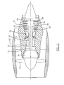
- a turbofan gas turbine engine incorporates an embodiment of the present invention, presented as an example of the application of the present invention, and includes a housing or a nacelle 10, a core casing 13, a low pressure spool assembly seen generally at 12 which includes a fan 14, low pressure compressor 16 and low pressure turbine 18, and a high pressure spool assembly seen generally at 20 which includes a high pressure compressor 22 and a high pressure turbine 24. There is provided a burner 25 for generating combustion gases.
- the low pressure turbine 18 and high pressure turbine 24 include a plurality of rotor stages 28 and stator vane stages 30.
- each of the rotor stages 28 has a plurality of rotor blades 33 encircled by a turbine shroud assembly 32 and each of the stator vane stages 30 includes a stator vane assembly 34 which is positioned upstream and/or downstream of a rotor stage 31, for directing combustion gases into or out of an annular gas path 36 within a corresponding turbine shroud assembly 32, and through the corresponding rotor stage 31.
- the stator vane assembly 34 for example a first stage of a low pressure turbine (LPT) vane assembly, is disposed, for example, downstream of the shroud assembly 32 of one rotor stage 28, and includes, for example a plurality of stator vane segments (not indicated) joined one to another in a circumferential direction to form a turbine vane outer shroud 38 which comprises a plurality of axial stator vanes 40 (only a portion of one is shown) which divide a downstream section of the annular gas path 36 relative to the rotor stage 28, into sectoral gas passages for directing combustion gas flow out of the rotor stage 28.
- LPT low pressure turbine
- the shroud assembly 32 in the rotor stage 28 includes a plurality of shroud segments 42 (only one shown) each of which includes a platform 44 having front and rear radial legs 46, 48 with respective hooks (not indicated).
- the shroud segments 42 are joined one to another in a circumferential direction and thereby form the shroud assembly 32.
- each shroud segment 42 has outer and inner surfaces 50, 52 and is defined axially between leading and trailing ends 54, 56, and circumferentially between opposite sides 58, 60 thereof.
- the platforms 44 of the segments collectively form a turbine shroud ring (not indicated) which encircles the rotor blades 33 and in combination with the rotor stage 28, defines a section of the annular gas path 36.
- the turbine shroud ring is disposed immediately upstream of and abuts the turbine vane outer shroud 38, to thereby form a portion of an outer wall (not indicated) of the annular gas path 36.
- the front and rear radial legs 46, 48 are axially spaced apart and integrally extend from the outer surface 50 radially and outwardly such that the hooks of the front a rear radial legs 46, 48 are conventionally connected with an annular shroud support structure 62 which is formed with a plurality of shroud support segments (not indicated) and is in turn supported within the core casing 13.
- An annular cavity 64 is thus defined axially between the front and rear legs 46, 48 and radially between the platforms 44 of the shroud segments 42 and the annular shroud support structure 62.
- the annular middle cavity is in fluid communication with a cooling air source, for example bleed air from the low or high pressure compressors 16, 22 and thus the cooling air under pressure is introduced into and accommodated within the annular cavity 64.
- each shroud segment 42 preferably includes a passage, for example a plurality of holes 66 extending axially within the platform 44 for directing cooling air therethrough for transpiration cooling of the platform 44.
- a groove 68 extending in a circumferential direction with opposite ends closed is provided, for example, on the outer surface 50 of the platform 44 such that holes 66 can be drilled from the trailing end 56 of the platform straightly and axially towards and terminate at the groove 68.
- the groove 68 forms a common inlet of the holes 66 for intake of cooling air accommodated within the cavity 64.
- other types of outlets can be made to achieve the convenience of the hole drilling process.
- outlets of the holes 66 in order to adequately discharge the cooling air from the holes 66 and reduce the contact surface of the trailing end 56 of the platform 44 of the shroud segments 42 with respect to the turbine vane outer shroud 38.
- an elongate recess 70 is provided in the trailing end 56 of the platform 44 with an opening on the inner surface 52 of the platform 44, thereby forming a common outlet of the holes 66 to discharge the cooling air, for example to the gas path 36.
- Other types of outlets can be used for adequately discharging the cooling air from the holes 66.
- the groove 68 is in fluid communication with the middle cavity 64 and thus cooling air introduced into the cavity 64 is directed into and through the axial holes 66 for effectively cooling the platform 44 of the shroud segments 42.
- the cooling air is then discharged through the elongate recess 70 at the trailing end 56 of the platform 42, impinging on a downstream engine part such as the turbine vane outer shroud 38, before entering the gas path 36.
- the groove 68 which functions as the common inlet of the holes 66 is preferably located close to the front leg 46 such that the holes 66 extend through a major section of the entire axial length of the platform 44 of the shroud segment 42, thereby efficiently cooling the platform 44 of the shroud segment 42.
- the holes 66 are preferably substantially evenly spaced apart in a circumferential direction and are preferably aligned with the turbine vane outer shroud. Thus, the cooling air impinges on the leading end of the turbine vane outer shroud 38.
- the number of holes 66 in each shroud segment 42 is determined such that the cooling air discharged from the holes 66 effectively cools the entire circumference of the leading end of the turbine vane outer shroud 38.
- cooling air introduced into the cavity 64 is directed within and through the platforms 44 of the shroud segments 42 via the holes 66, in order to cool the turbine shroud ring.
- cooling air flowing through the substantially axial straight holes 66 forms a plurality of substantially straight axial cooling air streams directed towards the leading end of the turbine vane outer shroud 38, preferably with a high velocity thereof, for impingement cooling on the turbine vane outer shroud 38.
- the substantially axial straight holes 66 direct the cooling air through the entire length thereof, thereby forming substantially straight cooling air streams with relatively high directionality.
- the substantially straight cooling air streams are more individually focused and interfere less with adjacent air streams when approaching the leading end of the turbine vane outer shroud 38, which results in greater impingement effects on the leading end of the turbine vane outer shroud 38.
Landscapes
- Engineering & Computer Science (AREA)
- Mechanical Engineering (AREA)
- General Engineering & Computer Science (AREA)
- Turbine Rotor Nozzle Sealing (AREA)
Applications Claiming Priority (3)
| Application Number | Priority Date | Filing Date | Title |
|---|---|---|---|
| US11/183,922 US7374395B2 (en) | 2005-07-19 | 2005-07-19 | Turbine shroud segment feather seal located in radial shroud legs |
| US11/183,741 US7520715B2 (en) | 2005-07-19 | 2005-07-19 | Turbine shroud segment transpiration cooling with individual cast inlet and outlet cavities |
| US11/184,843 US20070020088A1 (en) | 2005-07-20 | 2005-07-20 | Turbine shroud segment impingement cooling on vane outer shroud |
Publications (3)
| Publication Number | Publication Date |
|---|---|
| EP1746254A2 true EP1746254A2 (fr) | 2007-01-24 |
| EP1746254A3 EP1746254A3 (fr) | 2010-03-10 |
| EP1746254B1 EP1746254B1 (fr) | 2016-03-23 |
Family
ID=36917241
Family Applications (1)
| Application Number | Title | Priority Date | Filing Date |
|---|---|---|---|
| EP06253774.1A Active EP1746254B1 (fr) | 2005-07-19 | 2006-07-19 | Dispositif et méthode de refroidissement d'une virole de turbine et de l'anneau externe d'une aube statorique de turbine |
Country Status (1)
| Country | Link |
|---|---|
| EP (1) | EP1746254B1 (fr) |
Cited By (3)
| Publication number | Priority date | Publication date | Assignee | Title |
|---|---|---|---|---|
| EP1775423A3 (fr) * | 2005-10-14 | 2010-05-19 | General Electric Company | Segment de virole pour turbine |
| KR20150038256A (ko) * | 2010-04-20 | 2015-04-08 | 미츠비시 쥬고교 가부시키가이샤 | 분할 링 냉각 구조 |
| EP2855891B1 (fr) * | 2012-06-04 | 2022-05-11 | Raytheon Technologies Corporation | Joint d'étanchéité vis-à-vis de l'air externe à lame pour un moteur à turbine à gaz |
Citations (1)
| Publication number | Priority date | Publication date | Assignee | Title |
|---|---|---|---|---|
| US6899518B2 (en) | 2002-12-23 | 2005-05-31 | Pratt & Whitney Canada Corp. | Turbine shroud segment apparatus for reusing cooling air |
Family Cites Families (5)
| Publication number | Priority date | Publication date | Assignee | Title |
|---|---|---|---|---|
| FR2519374B1 (fr) * | 1982-01-07 | 1986-01-24 | Snecma | Dispositif de refroidissement des talons d'aubes mobiles d'une turbine |
| JPH0234731U (fr) * | 1988-08-30 | 1990-03-06 | ||
| JP3779517B2 (ja) * | 2000-01-21 | 2006-05-31 | 株式会社日立製作所 | ガスタービン |
| JP2002201913A (ja) * | 2001-01-09 | 2002-07-19 | Mitsubishi Heavy Ind Ltd | ガスタービンの分割壁およびシュラウド |
| JP4698847B2 (ja) * | 2001-01-19 | 2011-06-08 | 三菱重工業株式会社 | ガスタービン分割環 |
-
2006
- 2006-07-19 EP EP06253774.1A patent/EP1746254B1/fr active Active
Patent Citations (1)
| Publication number | Priority date | Publication date | Assignee | Title |
|---|---|---|---|---|
| US6899518B2 (en) | 2002-12-23 | 2005-05-31 | Pratt & Whitney Canada Corp. | Turbine shroud segment apparatus for reusing cooling air |
Cited By (3)
| Publication number | Priority date | Publication date | Assignee | Title |
|---|---|---|---|---|
| EP1775423A3 (fr) * | 2005-10-14 | 2010-05-19 | General Electric Company | Segment de virole pour turbine |
| KR20150038256A (ko) * | 2010-04-20 | 2015-04-08 | 미츠비시 쥬고교 가부시키가이샤 | 분할 링 냉각 구조 |
| EP2855891B1 (fr) * | 2012-06-04 | 2022-05-11 | Raytheon Technologies Corporation | Joint d'étanchéité vis-à-vis de l'air externe à lame pour un moteur à turbine à gaz |
Also Published As
| Publication number | Publication date |
|---|---|
| EP1746254B1 (fr) | 2016-03-23 |
| EP1746254A3 (fr) | 2010-03-10 |
Similar Documents
| Publication | Publication Date | Title |
|---|---|---|
| US20080232963A1 (en) | Turbine shroud segment transpiration cooling with individual cast inlet and outlet cavities | |
| US7374395B2 (en) | Turbine shroud segment feather seal located in radial shroud legs | |
| CA2688099C (fr) | Appareil de poussee en avant de compresseur centrifuge et de refroidissement de turbine | |
| US8087249B2 (en) | Turbine cooling air from a centrifugal compressor | |
| US11655718B2 (en) | Blade with tip rail, cooling | |
| CN1683772B (zh) | 涡轮环 | |
| US8573925B2 (en) | Cooled component for a gas turbine engine | |
| JP2017110652A (ja) | 活性高圧圧縮機クリアランス制御 | |
| US20190218925A1 (en) | Turbine engine shroud | |
| US20070020088A1 (en) | Turbine shroud segment impingement cooling on vane outer shroud | |
| CN108869047A (zh) | 具有冷却压缩机的燃气涡轮发动机 | |
| CN101672200A (zh) | 具有燕尾榫密封件的涡轮机轮叶及相关方法 | |
| US7246989B2 (en) | Shroud leading edge cooling | |
| US10837291B2 (en) | Turbine engine with component having a cooled tip | |
| CN108691571B (zh) | 具有流动增强器的发动机部件 | |
| EP2530244B1 (fr) | Stator entourant un rotor et procédé de refroidissement | |
| EP1746254B1 (fr) | Dispositif et méthode de refroidissement d'une virole de turbine et de l'anneau externe d'une aube statorique de turbine |
Legal Events
| Date | Code | Title | Description |
|---|---|---|---|
| PUAI | Public reference made under article 153(3) epc to a published international application that has entered the european phase |
Free format text: ORIGINAL CODE: 0009012 |
|
| AK | Designated contracting states |
Kind code of ref document: A2 Designated state(s): AT BE BG CH CY CZ DE DK EE ES FI FR GB GR HU IE IS IT LI LT LU LV MC NL PL PT RO SE SI SK TR |
|
| AX | Request for extension of the european patent |
Extension state: AL BA HR MK YU |
|
| PUAL | Search report despatched |
Free format text: ORIGINAL CODE: 0009013 |
|
| AK | Designated contracting states |
Kind code of ref document: A3 Designated state(s): AT BE BG CH CY CZ DE DK EE ES FI FR GB GR HU IE IS IT LI LT LU LV MC NL PL PT RO SE SI SK TR |
|
| AX | Request for extension of the european patent |
Extension state: AL BA HR MK RS |
|
| RIC1 | Information provided on ipc code assigned before grant |
Ipc: F01D 25/12 20060101ALI20100201BHEP Ipc: F01D 11/08 20060101AFI20100201BHEP Ipc: F01D 9/04 20060101ALI20100201BHEP |
|
| 17P | Request for examination filed |
Effective date: 20100512 |
|
| 17Q | First examination report despatched |
Effective date: 20100623 |
|
| AKX | Designation fees paid |
Designated state(s): DE FR GB |
|
| GRAP | Despatch of communication of intention to grant a patent |
Free format text: ORIGINAL CODE: EPIDOSNIGR1 |
|
| INTG | Intention to grant announced |
Effective date: 20150922 |
|
| GRAS | Grant fee paid |
Free format text: ORIGINAL CODE: EPIDOSNIGR3 |
|
| GRAA | (expected) grant |
Free format text: ORIGINAL CODE: 0009210 |
|
| AK | Designated contracting states |
Kind code of ref document: B1 Designated state(s): DE FR GB |
|
| REG | Reference to a national code |
Ref country code: GB Ref legal event code: FG4D |
|
| REG | Reference to a national code |
Ref country code: DE Ref legal event code: R096 Ref document number: 602006048324 Country of ref document: DE |
|
| REG | Reference to a national code |
Ref country code: FR Ref legal event code: PLFP Year of fee payment: 11 |
|
| REG | Reference to a national code |
Ref country code: DE Ref legal event code: R097 Ref document number: 602006048324 Country of ref document: DE |
|
| PLBE | No opposition filed within time limit |
Free format text: ORIGINAL CODE: 0009261 |
|
| STAA | Information on the status of an ep patent application or granted ep patent |
Free format text: STATUS: NO OPPOSITION FILED WITHIN TIME LIMIT |
|
| 26N | No opposition filed |
Effective date: 20170102 |
|
| REG | Reference to a national code |
Ref country code: FR Ref legal event code: PLFP Year of fee payment: 12 |
|
| REG | Reference to a national code |
Ref country code: DE Ref legal event code: R082 Ref document number: 602006048324 Country of ref document: DE Representative=s name: SCHMITT-NILSON SCHRAUD WAIBEL WOHLFROM PATENTA, DE |
|
| REG | Reference to a national code |
Ref country code: FR Ref legal event code: PLFP Year of fee payment: 13 |
|
| PGFP | Annual fee paid to national office [announced via postgrant information from national office to epo] |
Ref country code: DE Payment date: 20190620 Year of fee payment: 14 |
|
| REG | Reference to a national code |
Ref country code: DE Ref legal event code: R119 Ref document number: 602006048324 Country of ref document: DE |
|
| PG25 | Lapsed in a contracting state [announced via postgrant information from national office to epo] |
Ref country code: DE Free format text: LAPSE BECAUSE OF NON-PAYMENT OF DUE FEES Effective date: 20210202 |
|
| P01 | Opt-out of the competence of the unified patent court (upc) registered |
Effective date: 20230530 |
|
| PGFP | Annual fee paid to national office [announced via postgrant information from national office to epo] |
Ref country code: GB Payment date: 20250619 Year of fee payment: 20 |
|
| PGFP | Annual fee paid to national office [announced via postgrant information from national office to epo] |
Ref country code: FR Payment date: 20250620 Year of fee payment: 20 |