EP1746281A2 - Arrangement avec un circuit magnétique avec un connecteur orientable radialement - Google Patents
Arrangement avec un circuit magnétique avec un connecteur orientable radialement Download PDFInfo
- Publication number
- EP1746281A2 EP1746281A2 EP06114402A EP06114402A EP1746281A2 EP 1746281 A2 EP1746281 A2 EP 1746281A2 EP 06114402 A EP06114402 A EP 06114402A EP 06114402 A EP06114402 A EP 06114402A EP 1746281 A2 EP1746281 A2 EP 1746281A2
- Authority
- EP
- European Patent Office
- Prior art keywords
- arrangement
- magnetic circuit
- electrical connection
- housing component
- plug contact
- Prior art date
- Legal status (The legal status is an assumption and is not a legal conclusion. Google has not performed a legal analysis and makes no representation as to the accuracy of the status listed.)
- Granted
Links
- 238000004519 manufacturing process Methods 0.000 description 7
- 238000002347 injection Methods 0.000 description 3
- 239000007924 injection Substances 0.000 description 3
- 230000001105 regulatory effect Effects 0.000 description 3
- 239000000446 fuel Substances 0.000 description 2
- 238000009434 installation Methods 0.000 description 2
- 239000000243 solution Substances 0.000 description 2
- 238000004804 winding Methods 0.000 description 2
- 230000002411 adverse Effects 0.000 description 1
- 230000006835 compression Effects 0.000 description 1
- 238000007906 compression Methods 0.000 description 1
- 230000001419 dependent effect Effects 0.000 description 1
- 238000010586 diagram Methods 0.000 description 1
- 238000005553 drilling Methods 0.000 description 1
- 238000005538 encapsulation Methods 0.000 description 1
- 230000013011 mating Effects 0.000 description 1
- 230000002093 peripheral effect Effects 0.000 description 1
- 238000007789 sealing Methods 0.000 description 1
Images
Classifications
-
- F—MECHANICAL ENGINEERING; LIGHTING; HEATING; WEAPONS; BLASTING
- F02—COMBUSTION ENGINES; HOT-GAS OR COMBUSTION-PRODUCT ENGINE PLANTS
- F02M—SUPPLYING COMBUSTION ENGINES IN GENERAL WITH COMBUSTIBLE MIXTURES OR CONSTITUENTS THEREOF
- F02M63/00—Other fuel-injection apparatus having pertinent characteristics not provided for in groups F02M39/00 - F02M57/00 or F02M67/00; Details, component parts, or accessories of fuel-injection apparatus, not provided for in, or of interest apart from, the apparatus of groups F02M39/00 - F02M61/00 or F02M67/00; Combination of fuel pump with other devices, e.g. lubricating oil pump
- F02M63/02—Fuel-injection apparatus having several injectors fed by a common pumping element, or having several pumping elements feeding a common injector; Fuel-injection apparatus having provisions for cutting-out pumps, pumping elements, or injectors; Fuel-injection apparatus having provisions for variably interconnecting pumping elements and injectors alternatively
- F02M63/0225—Fuel-injection apparatus having a common rail feeding several injectors ; Means for varying pressure in common rails; Pumps feeding common rails
-
- F—MECHANICAL ENGINEERING; LIGHTING; HEATING; WEAPONS; BLASTING
- F02—COMBUSTION ENGINES; HOT-GAS OR COMBUSTION-PRODUCT ENGINE PLANTS
- F02M—SUPPLYING COMBUSTION ENGINES IN GENERAL WITH COMBUSTIBLE MIXTURES OR CONSTITUENTS THEREOF
- F02M51/00—Fuel-injection apparatus characterised by being operated electrically
- F02M51/005—Arrangement of electrical wires and connections, e.g. wire harness, sockets, plugs; Arrangement of electronic control circuits in or on fuel injection apparatus
-
- F—MECHANICAL ENGINEERING; LIGHTING; HEATING; WEAPONS; BLASTING
- F02—COMBUSTION ENGINES; HOT-GAS OR COMBUSTION-PRODUCT ENGINE PLANTS
- F02M—SUPPLYING COMBUSTION ENGINES IN GENERAL WITH COMBUSTIBLE MIXTURES OR CONSTITUENTS THEREOF
- F02M59/00—Pumps specially adapted for fuel-injection and not provided for in groups F02M39/00 -F02M57/00, e.g. rotary cylinder-block type of pumps
- F02M59/20—Varying fuel delivery in quantity or timing
- F02M59/36—Varying fuel delivery in quantity or timing by variably-timed valves controlling fuel passages to pumping elements or overflow passages
- F02M59/366—Valves being actuated electrically
-
- F—MECHANICAL ENGINEERING; LIGHTING; HEATING; WEAPONS; BLASTING
- F02—COMBUSTION ENGINES; HOT-GAS OR COMBUSTION-PRODUCT ENGINE PLANTS
- F02M—SUPPLYING COMBUSTION ENGINES IN GENERAL WITH COMBUSTIBLE MIXTURES OR CONSTITUENTS THEREOF
- F02M63/00—Other fuel-injection apparatus having pertinent characteristics not provided for in groups F02M39/00 - F02M57/00 or F02M67/00; Details, component parts, or accessories of fuel-injection apparatus, not provided for in, or of interest apart from, the apparatus of groups F02M39/00 - F02M61/00 or F02M67/00; Combination of fuel pump with other devices, e.g. lubricating oil pump
- F02M63/0012—Valves
- F02M63/0014—Valves characterised by the valve actuating means
- F02M63/0015—Valves characterised by the valve actuating means electrical, e.g. using solenoid
-
- F—MECHANICAL ENGINEERING; LIGHTING; HEATING; WEAPONS; BLASTING
- F16—ENGINEERING ELEMENTS AND UNITS; GENERAL MEASURES FOR PRODUCING AND MAINTAINING EFFECTIVE FUNCTIONING OF MACHINES OR INSTALLATIONS; THERMAL INSULATION IN GENERAL
- F16K—VALVES; TAPS; COCKS; ACTUATING-FLOATS; DEVICES FOR VENTING OR AERATING
- F16K27/00—Construction of housing; Use of materials therefor
- F16K27/02—Construction of housing; Use of materials therefor of lift valves
- F16K27/029—Electromagnetically actuated valves
-
- F—MECHANICAL ENGINEERING; LIGHTING; HEATING; WEAPONS; BLASTING
- F16—ENGINEERING ELEMENTS AND UNITS; GENERAL MEASURES FOR PRODUCING AND MAINTAINING EFFECTIVE FUNCTIONING OF MACHINES OR INSTALLATIONS; THERMAL INSULATION IN GENERAL
- F16K—VALVES; TAPS; COCKS; ACTUATING-FLOATS; DEVICES FOR VENTING OR AERATING
- F16K31/00—Actuating devices; Operating means; Releasing devices
- F16K31/02—Actuating devices; Operating means; Releasing devices electric; magnetic
- F16K31/06—Actuating devices; Operating means; Releasing devices electric; magnetic using a magnet, e.g. diaphragm valves, cutting off by means of a liquid
-
- F—MECHANICAL ENGINEERING; LIGHTING; HEATING; WEAPONS; BLASTING
- F02—COMBUSTION ENGINES; HOT-GAS OR COMBUSTION-PRODUCT ENGINE PLANTS
- F02M—SUPPLYING COMBUSTION ENGINES IN GENERAL WITH COMBUSTIBLE MIXTURES OR CONSTITUENTS THEREOF
- F02M2200/00—Details of fuel-injection apparatus, not otherwise provided for
- F02M2200/80—Fuel injection apparatus manufacture, repair or assembly
Definitions
- the invention relates to an arrangement with a magnetic circuit with a radially orientable plug contact, for example, this is an arrangement in an electromagnetic pressure control valve, which is adjusted over a duty cycle of the power supply.
- pressure control valves are used for pressure control in storage injection systems. These injection systems include a high-pressure accumulator, which is supplied via a high-pressure pump with high-pressure fuel.
- a pressure control is involved, i. a pressure sensor axially arranged on the high-pressure storage space and an electromagnetic pressure control valve, whereby the pressure in the high-pressure accumulator chamber is adjusted quickly and precisely, so that a constant system pressure at different flow rates is possible.
- a plug contact for an electrical connection can not be made axially, but the plug contact is oriented in the radial direction, wherein an end position afflicted with a certain angular tolerance is set.
- An exact angular orientation of a plug contact is often not possible.
- only a very limited space available for such arrangements with a magnetic circuit is only a very limited space available for such arrangements with a magnetic circuit.
- this results in the need for a compact arrangement which on the other hand results in high demands on the manufacturing tolerances and complex geometries of the components involved, which adversely affect the costs.
- connection of an electrical connection with a housing component, in which a magnetic coil is integrated by means of a flange, a union nut, a threaded connection, being provided on both components at an angle oriented threads, or via sliding contacts between the solenoid and electrical connection.
- This is intended to achieve a specific angular orientation of a plug contact included in the electrical connection in the mounted state of the arrangement at its destination.
- an adjustable pressure control valve with an electrical connection for fuel injection systems is known, which is associated with a high-pressure delivery unit, which is arranged between a high-pressure side and a low-pressure side and comprises a valve element which can be controlled via an electric actuator.
- the electric actuator is designed as an electromagnetic actuator.
- the pressure regulating valve has an electrical connection which is connected to a housing component via a screw connection. In the housing component, an anchor plate is received, which acts on the one hand by a compression spring and on the other hand, a likewise disposed in the housing component electromagnet opposite.
- the housing component of the pressure regulating valve has a deformable region, by means of which a gap can be set between the surfaces of the electrically controllable actuator arrangement of the magnet system anchor plate / magnetic core when the pressure regulating valve is mounted on a receiving body.
- a gap can be set between the surfaces of the electrically controllable actuator arrangement of the magnet system anchor plate / magnetic core when the pressure regulating valve is mounted on a receiving body.
- the object of the present invention is to provide an arrangement with a magnetic circuit on which an electrical connection in the form of a plug contact with a radially orientable orientation is provided.
- Radial angular orientation of the integrated plug contact of the arrangement proposed according to the invention with a magnetic circuit comprising a preassembled unit and a housing component accommodating this unit is possible after installation of the entire arrangement with a magnetic circuit in a receiving body in a narrow angular tolerance range.
- the arrangement with a magnetic circuit comes without additional components, in particular union nut or flange, from and therefore offers a cost effective and easy to implement solution. Close manufacturing tolerances and complex geometries of the individual components are not necessary to achieve a radial alignment of the plug contact according to the requirements after installation of the arrangement with a magnetic circuit.
- the arrangement with a magnetic circuit comprises a preassembled unit, which combines a magnetic coil, at least one intermediate disc and a cover plate with an integrated electrical connection. These components are rotatably connected to each other in an arbitrary or with respect to a reference surface orientable position. The rotationally fixed connection of the individual components can be done by friction and / or positive engagement.
- This preassembled unit is accommodated in a housing component, whereby the proposed arrangement is provided with a magnetic circuit whose electrical connection has a radially orientable plug contact.
- the arrangement with a magnetic circuit can be accommodated, for example, by an axial screw in a receiving body.
- the final radial alignment of the plug contact of the electrical connection can be made in the desired Winkelendposition.
- the entire preassembled unit consisting of magnetic coil, washer and end cap with integrated electrical connection, brought by applying a certain minimum torque in the desired Winkelendposition.
- the angle end position is with great accuracy, i. Affected with a narrow angle tolerance range, adjustable.
- the set Winkelendposition can be secured by friction. Alternatively, by a subsequent manufacturing step, e.g. by notching, the Winkelendposition be secured form-fitting.
- any radial angular orientation of a male contact of an electrical connection, integrated into a magnetic component having arrangement can be achieved.
- a magnetic circuit for example, part of a pressure control valve
- the electrical connection included can be aligned in a biased with a narrow angular tolerance radial orientation, wherein as the reference surface Component itself, with which the assembly is connected to a magnetic circuit, ie, the high-pressure pump or the high-pressure storage chamber, acts and the alignment is no longer bound to reference surfaces, such as a surface of a hexagon.
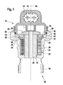
- the arrangement with a magnetic circuit 10 has a housing component 12 and a cover 14.
- the end cover 14 has an electrical connection 16, wherein a plug contact is integrated, via which an electrically controllable actuator integrated in the arrangement with a magnetic circuit 10 can be activated or deactivated.
- the electrical actuator is formed in the embodiment as an electromagnetic actuator whose details are not shown.
- a bore 18 is provided, into which a sleeve 20 is received.
- the housing 12 and the sleeve 20 may be made in one piece.
- the sleeve 20 serves for example to receive an anchor part, not shown.
- the sleeve 20 is partially enclosed by a preassembled magnetic coil 22, which has a winding unit 24 and an overmolding in the form of a sleeve 26 made of plastic such as plastic.
- PPS includes.
- the magnet coil 22 comprises a collar-shaped shoulder 28 which, for assembly reasons, has a conically tapering peripheral region 30.
- an annular surface 32 of the collar-shaped shoulder 28 of the magnetic coil 22 is located on an intermediate disc 34, wherein at the contact surface between the annular surface 32 and the intermediate disc 34 is a positive and / or frictional engagement, which can be made in the encapsulation.
- the intermediate disc 34 is in a form and / or frictional engagement with the end cover 14.
- a positive connection the connection between an outer periphery 36 of the washer 34 and a receiving portion 58 of the end cover 14 via a wedge or multi-wedge connection, a polygonal profile or a claw-shaped connection done.
- an end face 38 of the intermediate disk 34 it is likewise possible for an end face 38 of the intermediate disk 34 to be in positive engagement with a correspondingly formed region 60 of the end cover 14.
- a correspondingly shaped periphery 36 of the washer 34 ie, for example, serrated or polygonal profile, provides a cost-effective connection.
- the preassembled unit comprising solenoid 22, washer 34 and end cap 14 offers the advantage that the elements relevant to an electromagnetic actuator, i. Magnetic core, in which the solenoids of an electromagnet are accommodated, and an anchor plate 54, which is received for example in the end cover 14, can be brought into a predetermined position to each other, which does not change by a radial orientation of the electrical connection 16.
- an electromagnetic actuator i. Magnetic core, in which the solenoids of an electromagnet are accommodated, and an anchor plate 54, which is received for example in the end cover 14
- an anchor plate 54 which is received for example in the end cover 14
- the preassembled unit, including solenoid 22, washer 34 and end cap 14, is received in the housing component 12.
- the circumference 40 of the end cover 14 is formed such that the end cover 14, for example by means of a flange 42 or alternatively by means of a union nut with the housing component 12 is connectable.
- the end cover 14, including the intermediate disk 34 and the magnet coil 22 connected therewith in a rotationally fixed manner is pressed against a surface 44 of the housing component 12.
- a shoulder 46 is formed on the circumference 40 of the end cover 14, against which a sealing ring 48 abuts, which seals the end cover 14 against the housing component 12.
- the housing component 12 comprises at an end 50 opposite the end cap an external thread 52, which can be screwed into a corresponding thread on a - not shown - receiving body.
- the final radial orientation of the plug contact 16 takes place with a defined minimum torque in any Winkelendposition.
- the preassembled unit can be rotated 360 ° about its longitudinal axis 56.
Landscapes
- Engineering & Computer Science (AREA)
- General Engineering & Computer Science (AREA)
- Mechanical Engineering (AREA)
- Chemical & Material Sciences (AREA)
- Combustion & Propulsion (AREA)
- Physics & Mathematics (AREA)
- Electromagnetism (AREA)
- Magnetically Actuated Valves (AREA)
- Electrically Driven Valve-Operating Means (AREA)
- Electromagnets (AREA)
Applications Claiming Priority (1)
| Application Number | Priority Date | Filing Date | Title |
|---|---|---|---|
| DE102005033871A DE102005033871A1 (de) | 2005-07-20 | 2005-07-20 | Anordnung mit einem Magnetkreis mit radial orientierbarem Stecker |
Publications (3)
| Publication Number | Publication Date |
|---|---|
| EP1746281A2 true EP1746281A2 (fr) | 2007-01-24 |
| EP1746281A3 EP1746281A3 (fr) | 2007-03-07 |
| EP1746281B1 EP1746281B1 (fr) | 2012-04-18 |
Family
ID=37116035
Family Applications (1)
| Application Number | Title | Priority Date | Filing Date |
|---|---|---|---|
| EP06114402A Not-in-force EP1746281B1 (fr) | 2005-07-20 | 2006-05-23 | Arrangement avec un circuit magnétique avec un connecteur orientable radialement |
Country Status (3)
| Country | Link |
|---|---|
| EP (1) | EP1746281B1 (fr) |
| AT (1) | ATE554285T1 (fr) |
| DE (1) | DE102005033871A1 (fr) |
Cited By (3)
| Publication number | Priority date | Publication date | Assignee | Title |
|---|---|---|---|---|
| CN109243757A (zh) * | 2018-11-01 | 2019-01-18 | 零八电子集团四川力源电子有限公司 | 高压共轨高速电磁铁尾座结构 |
| CN109416011A (zh) * | 2016-06-27 | 2019-03-01 | 罗伯特·博世有限公司 | 用于制造用于喷射燃料的喷射器的方法 |
| WO2019134990A1 (fr) * | 2018-01-08 | 2019-07-11 | Cpt Group Gmbh | Pompe à carburant haute pression pour système d'injection de carburant |
Families Citing this family (1)
| Publication number | Priority date | Publication date | Assignee | Title |
|---|---|---|---|---|
| CN119252596B (zh) * | 2024-10-16 | 2025-11-04 | 安徽华东光电技术研究所有限公司 | 一种用于高强度磁场磁系统调节的定位工装 |
Citations (1)
| Publication number | Priority date | Publication date | Assignee | Title |
|---|---|---|---|---|
| DE10214084A1 (de) | 2002-03-28 | 2003-10-30 | Bosch Gmbh Robert | Einstellbares Druckregelventil für Kraftstoffeinspritzsysteme |
Family Cites Families (7)
| Publication number | Priority date | Publication date | Assignee | Title |
|---|---|---|---|---|
| US5244180A (en) * | 1992-09-03 | 1993-09-14 | Siemens Automotive L.P. | Solenoid pre-loader |
| US5549274A (en) * | 1994-04-20 | 1996-08-27 | Cummins Engine Company, Inc. | Ball guide for an electronically actuated control valve |
| DE19832826C2 (de) * | 1998-07-21 | 2000-08-17 | Bosch Gmbh Robert | Montageverfahren für Kraftstoff-Einspritzventil und Vorsteuerventil sowie Kraftstoff-Einspritzventil |
| DE10131201A1 (de) * | 2001-06-28 | 2003-01-16 | Bosch Gmbh Robert | Magnetventil zur Steuerung eines Einspritzventils einer Brennkraftmaschine |
| DE10138756A1 (de) * | 2001-08-07 | 2003-02-20 | Bosch Gmbh Robert | Kraftstoffhochdruckspeicher |
| DE10222895A1 (de) * | 2002-05-23 | 2003-12-11 | Bosch Gmbh Robert | Hochdruckspeicher für Kraftstoffeinspritzsysteme mit integriertem Druckregelventil |
| DE10240880B4 (de) * | 2002-09-04 | 2016-12-01 | Robert Bosch Gmbh | Aktorverbindung an Kraftstoffinjektoren von Verbrennungskraftmaschinen |
-
2005
- 2005-07-20 DE DE102005033871A patent/DE102005033871A1/de not_active Withdrawn
-
2006
- 2006-05-23 EP EP06114402A patent/EP1746281B1/fr not_active Not-in-force
- 2006-05-23 AT AT06114402T patent/ATE554285T1/de active
Patent Citations (1)
| Publication number | Priority date | Publication date | Assignee | Title |
|---|---|---|---|---|
| DE10214084A1 (de) | 2002-03-28 | 2003-10-30 | Bosch Gmbh Robert | Einstellbares Druckregelventil für Kraftstoffeinspritzsysteme |
Cited By (3)
| Publication number | Priority date | Publication date | Assignee | Title |
|---|---|---|---|---|
| CN109416011A (zh) * | 2016-06-27 | 2019-03-01 | 罗伯特·博世有限公司 | 用于制造用于喷射燃料的喷射器的方法 |
| WO2019134990A1 (fr) * | 2018-01-08 | 2019-07-11 | Cpt Group Gmbh | Pompe à carburant haute pression pour système d'injection de carburant |
| CN109243757A (zh) * | 2018-11-01 | 2019-01-18 | 零八电子集团四川力源电子有限公司 | 高压共轨高速电磁铁尾座结构 |
Also Published As
| Publication number | Publication date |
|---|---|
| EP1746281B1 (fr) | 2012-04-18 |
| DE102005033871A1 (de) | 2007-01-25 |
| ATE554285T1 (de) | 2012-05-15 |
| EP1746281A3 (fr) | 2007-03-07 |
Similar Documents
| Publication | Publication Date | Title |
|---|---|---|
| DE102011013702B4 (de) | Elektromagnetischer Aktor | |
| EP2646709B1 (fr) | Actionneur pour dispositif de soupape d'amortissement réglable | |
| EP2156046B1 (fr) | Ajustement de trajet d'armature pour électrovanne | |
| EP2132432B1 (fr) | Tête magnétique pour électrovanne | |
| DE102013218854A1 (de) | Elektromagnetisch ansteuerbares Saugventil | |
| WO2018033278A1 (fr) | Soupape d'aspiration à actionnement électromagnétique et pompe à carburant haute pression | |
| EP1088182A1 (fr) | Electrovanne | |
| EP3172428B1 (fr) | Unité électromagnétique de réglage pour une soupape d'aspiration et une soupape d'aspiration | |
| EP3078036B1 (fr) | Soupape pour système hybride hydraulique | |
| DE102013218844A1 (de) | Elektromagnetisch ansteuerbares Saugventil | |
| EP1746281B1 (fr) | Arrangement avec un circuit magnétique avec un connecteur orientable radialement | |
| EP3353408B1 (fr) | Actionneur électrique de mécanisme de soupape | |
| DE102014202334A1 (de) | Hochdruckpumpe für ein Kraftstoffeinspritzsystem | |
| EP2209992B1 (fr) | Élément de pompage, bloc hydraulique avec élément de pompage, et procédé de montage | |
| DE102011086313B4 (de) | Magnetventil | |
| EP3204630A1 (fr) | Vanne proportionnelle à commande électromagnétique et pompe à carburant haute pression dotée d'une telle vanne proportionnelle | |
| EP3420257B1 (fr) | Électrovanne | |
| DE102007053800A1 (de) | Kraftstoffsystem einer Brennkraftmaschine | |
| DE102014201101A1 (de) | Elektromagnetisch ansteuerbares Saugventil | |
| DE102004025969A1 (de) | Magnetventil | |
| DE102011089935A1 (de) | Magnetbaugruppe für ein Magnetventil, Magnetventil | |
| DE102017217489A1 (de) | Elektromagnetisch betätigbares Einlassventil und Hochdruckpumpe mit Einlassventil | |
| EP3209878A1 (fr) | Soupape d'aspiration à commande électromagnétique, pompe à haute pression pourvue d'une telle soupape d'aspiration et procédé de raccordement d'une telle soupape d'aspiration à un élément de carter d'une pompe à haute pression | |
| DE102016224722A1 (de) | Elektromagnetisch betätigbares Einlassventil und Hochdruckpumpe mit Einlassventil | |
| EP1355096B1 (fr) | Soupape proportionnelle magnétique |
Legal Events
| Date | Code | Title | Description |
|---|---|---|---|
| PUAI | Public reference made under article 153(3) epc to a published international application that has entered the european phase |
Free format text: ORIGINAL CODE: 0009012 |
|
| AK | Designated contracting states |
Kind code of ref document: A2 Designated state(s): AT BE BG CH CY CZ DE DK EE ES FI FR GB GR HU IE IS IT LI LT LU LV MC NL PL PT RO SE SI SK TR |
|
| AX | Request for extension of the european patent |
Extension state: AL BA HR MK YU |
|
| PUAL | Search report despatched |
Free format text: ORIGINAL CODE: 0009013 |
|
| AK | Designated contracting states |
Kind code of ref document: A3 Designated state(s): AT BE BG CH CY CZ DE DK EE ES FI FR GB GR HU IE IS IT LI LT LU LV MC NL PL PT RO SE SI SK TR |
|
| AX | Request for extension of the european patent |
Extension state: AL BA HR MK YU |
|
| 17P | Request for examination filed |
Effective date: 20070907 |
|
| 17Q | First examination report despatched |
Effective date: 20071015 |
|
| AKX | Designation fees paid |
Designated state(s): AT BE BG CH CY CZ DE DK EE ES FI FR GB GR HU IE IS IT LI LT LU LV MC NL PL PT RO SE SI SK TR |
|
| REG | Reference to a national code |
Ref country code: DE Ref legal event code: R079 Ref document number: 502006011312 Country of ref document: DE Free format text: PREVIOUS MAIN CLASS: F02M0059360000 Ipc: F02M0063020000 |
|
| RIC1 | Information provided on ipc code assigned before grant |
Ipc: F16K 27/02 20060101ALI20111208BHEP Ipc: F02M 63/00 20060101ALI20111208BHEP Ipc: F02M 63/02 20060101AFI20111208BHEP Ipc: F02M 51/00 20060101ALI20111208BHEP Ipc: F02M 59/36 20060101ALI20111208BHEP Ipc: F16K 31/06 20060101ALI20111208BHEP |
|
| GRAP | Despatch of communication of intention to grant a patent |
Free format text: ORIGINAL CODE: EPIDOSNIGR1 |
|
| GRAS | Grant fee paid |
Free format text: ORIGINAL CODE: EPIDOSNIGR3 |
|
| GRAA | (expected) grant |
Free format text: ORIGINAL CODE: 0009210 |
|
| AK | Designated contracting states |
Kind code of ref document: B1 Designated state(s): AT BE BG CH CY CZ DE DK EE ES FI FR GB GR HU IE IS IT LI LT LU LV MC NL PL PT RO SE SI SK TR |
|
| REG | Reference to a national code |
Ref country code: GB Ref legal event code: FG4D Free format text: NOT ENGLISH |
|
| REG | Reference to a national code |
Ref country code: CH Ref legal event code: EP |
|
| REG | Reference to a national code |
Ref country code: IE Ref legal event code: FG4D Free format text: LANGUAGE OF EP DOCUMENT: GERMAN |
|
| REG | Reference to a national code |
Ref country code: AT Ref legal event code: REF Ref document number: 554285 Country of ref document: AT Kind code of ref document: T Effective date: 20120515 |
|
| REG | Reference to a national code |
Ref country code: DE Ref legal event code: R096 Ref document number: 502006011312 Country of ref document: DE Effective date: 20120614 |
|
| REG | Reference to a national code |
Ref country code: NL Ref legal event code: VDEP Effective date: 20120418 |
|
| LTIE | Lt: invalidation of european patent or patent extension |
Effective date: 20120418 |
|
| PG25 | Lapsed in a contracting state [announced via postgrant information from national office to epo] |
Ref country code: SE Free format text: LAPSE BECAUSE OF FAILURE TO SUBMIT A TRANSLATION OF THE DESCRIPTION OR TO PAY THE FEE WITHIN THE PRESCRIBED TIME-LIMIT Effective date: 20120418 Ref country code: CY Free format text: LAPSE BECAUSE OF FAILURE TO SUBMIT A TRANSLATION OF THE DESCRIPTION OR TO PAY THE FEE WITHIN THE PRESCRIBED TIME-LIMIT Effective date: 20120418 Ref country code: FI Free format text: LAPSE BECAUSE OF FAILURE TO SUBMIT A TRANSLATION OF THE DESCRIPTION OR TO PAY THE FEE WITHIN THE PRESCRIBED TIME-LIMIT Effective date: 20120418 Ref country code: LT Free format text: LAPSE BECAUSE OF FAILURE TO SUBMIT A TRANSLATION OF THE DESCRIPTION OR TO PAY THE FEE WITHIN THE PRESCRIBED TIME-LIMIT Effective date: 20120418 Ref country code: PL Free format text: LAPSE BECAUSE OF FAILURE TO SUBMIT A TRANSLATION OF THE DESCRIPTION OR TO PAY THE FEE WITHIN THE PRESCRIBED TIME-LIMIT Effective date: 20120418 Ref country code: IS Free format text: LAPSE BECAUSE OF FAILURE TO SUBMIT A TRANSLATION OF THE DESCRIPTION OR TO PAY THE FEE WITHIN THE PRESCRIBED TIME-LIMIT Effective date: 20120818 |
|
| BERE | Be: lapsed |
Owner name: ROBERT BOSCH G.M.B.H. Effective date: 20120531 |
|
| PG25 | Lapsed in a contracting state [announced via postgrant information from national office to epo] |
Ref country code: SI Free format text: LAPSE BECAUSE OF FAILURE TO SUBMIT A TRANSLATION OF THE DESCRIPTION OR TO PAY THE FEE WITHIN THE PRESCRIBED TIME-LIMIT Effective date: 20120418 Ref country code: GR Free format text: LAPSE BECAUSE OF FAILURE TO SUBMIT A TRANSLATION OF THE DESCRIPTION OR TO PAY THE FEE WITHIN THE PRESCRIBED TIME-LIMIT Effective date: 20120719 Ref country code: LV Free format text: LAPSE BECAUSE OF FAILURE TO SUBMIT A TRANSLATION OF THE DESCRIPTION OR TO PAY THE FEE WITHIN THE PRESCRIBED TIME-LIMIT Effective date: 20120418 Ref country code: PT Free format text: LAPSE BECAUSE OF FAILURE TO SUBMIT A TRANSLATION OF THE DESCRIPTION OR TO PAY THE FEE WITHIN THE PRESCRIBED TIME-LIMIT Effective date: 20120820 |
|
| PG25 | Lapsed in a contracting state [announced via postgrant information from national office to epo] |
Ref country code: MC Free format text: LAPSE BECAUSE OF NON-PAYMENT OF DUE FEES Effective date: 20120531 |
|
| REG | Reference to a national code |
Ref country code: CH Ref legal event code: PL |
|
| PG25 | Lapsed in a contracting state [announced via postgrant information from national office to epo] |
Ref country code: NL Free format text: LAPSE BECAUSE OF FAILURE TO SUBMIT A TRANSLATION OF THE DESCRIPTION OR TO PAY THE FEE WITHIN THE PRESCRIBED TIME-LIMIT Effective date: 20120418 Ref country code: CH Free format text: LAPSE BECAUSE OF NON-PAYMENT OF DUE FEES Effective date: 20120531 Ref country code: SK Free format text: LAPSE BECAUSE OF FAILURE TO SUBMIT A TRANSLATION OF THE DESCRIPTION OR TO PAY THE FEE WITHIN THE PRESCRIBED TIME-LIMIT Effective date: 20120418 Ref country code: DK Free format text: LAPSE BECAUSE OF FAILURE TO SUBMIT A TRANSLATION OF THE DESCRIPTION OR TO PAY THE FEE WITHIN THE PRESCRIBED TIME-LIMIT Effective date: 20120418 Ref country code: EE Free format text: LAPSE BECAUSE OF FAILURE TO SUBMIT A TRANSLATION OF THE DESCRIPTION OR TO PAY THE FEE WITHIN THE PRESCRIBED TIME-LIMIT Effective date: 20120418 Ref country code: CZ Free format text: LAPSE BECAUSE OF FAILURE TO SUBMIT A TRANSLATION OF THE DESCRIPTION OR TO PAY THE FEE WITHIN THE PRESCRIBED TIME-LIMIT Effective date: 20120418 Ref country code: LI Free format text: LAPSE BECAUSE OF NON-PAYMENT OF DUE FEES Effective date: 20120531 Ref country code: RO Free format text: LAPSE BECAUSE OF FAILURE TO SUBMIT A TRANSLATION OF THE DESCRIPTION OR TO PAY THE FEE WITHIN THE PRESCRIBED TIME-LIMIT Effective date: 20120418 |
|
| PLBE | No opposition filed within time limit |
Free format text: ORIGINAL CODE: 0009261 |
|
| STAA | Information on the status of an ep patent application or granted ep patent |
Free format text: STATUS: NO OPPOSITION FILED WITHIN TIME LIMIT |
|
| REG | Reference to a national code |
Ref country code: IE Ref legal event code: MM4A |
|
| PG25 | Lapsed in a contracting state [announced via postgrant information from national office to epo] |
Ref country code: IT Free format text: LAPSE BECAUSE OF FAILURE TO SUBMIT A TRANSLATION OF THE DESCRIPTION OR TO PAY THE FEE WITHIN THE PRESCRIBED TIME-LIMIT Effective date: 20120418 Ref country code: BE Free format text: LAPSE BECAUSE OF NON-PAYMENT OF DUE FEES Effective date: 20120531 |
|
| REG | Reference to a national code |
Ref country code: FR Ref legal event code: ST Effective date: 20130131 |
|
| 26N | No opposition filed |
Effective date: 20130121 |
|
| GBPC | Gb: european patent ceased through non-payment of renewal fee |
Effective date: 20120718 |
|
| PG25 | Lapsed in a contracting state [announced via postgrant information from national office to epo] |
Ref country code: GB Free format text: LAPSE BECAUSE OF NON-PAYMENT OF DUE FEES Effective date: 20120718 Ref country code: IE Free format text: LAPSE BECAUSE OF NON-PAYMENT OF DUE FEES Effective date: 20120523 Ref country code: FR Free format text: LAPSE BECAUSE OF NON-PAYMENT OF DUE FEES Effective date: 20120618 Ref country code: ES Free format text: LAPSE BECAUSE OF FAILURE TO SUBMIT A TRANSLATION OF THE DESCRIPTION OR TO PAY THE FEE WITHIN THE PRESCRIBED TIME-LIMIT Effective date: 20120729 |
|
| REG | Reference to a national code |
Ref country code: DE Ref legal event code: R097 Ref document number: 502006011312 Country of ref document: DE Effective date: 20130121 |
|
| REG | Reference to a national code |
Ref country code: AT Ref legal event code: MM01 Ref document number: 554285 Country of ref document: AT Kind code of ref document: T Effective date: 20120523 |
|
| PG25 | Lapsed in a contracting state [announced via postgrant information from national office to epo] |
Ref country code: BG Free format text: LAPSE BECAUSE OF FAILURE TO SUBMIT A TRANSLATION OF THE DESCRIPTION OR TO PAY THE FEE WITHIN THE PRESCRIBED TIME-LIMIT Effective date: 20120718 Ref country code: AT Free format text: LAPSE BECAUSE OF NON-PAYMENT OF DUE FEES Effective date: 20120523 |
|
| PG25 | Lapsed in a contracting state [announced via postgrant information from national office to epo] |
Ref country code: TR Free format text: LAPSE BECAUSE OF FAILURE TO SUBMIT A TRANSLATION OF THE DESCRIPTION OR TO PAY THE FEE WITHIN THE PRESCRIBED TIME-LIMIT Effective date: 20120418 |
|
| PG25 | Lapsed in a contracting state [announced via postgrant information from national office to epo] |
Ref country code: LU Free format text: LAPSE BECAUSE OF NON-PAYMENT OF DUE FEES Effective date: 20120523 |
|
| PG25 | Lapsed in a contracting state [announced via postgrant information from national office to epo] |
Ref country code: HU Free format text: LAPSE BECAUSE OF FAILURE TO SUBMIT A TRANSLATION OF THE DESCRIPTION OR TO PAY THE FEE WITHIN THE PRESCRIBED TIME-LIMIT Effective date: 20060523 |
|
| PGFP | Annual fee paid to national office [announced via postgrant information from national office to epo] |
Ref country code: DE Payment date: 20140724 Year of fee payment: 9 |
|
| REG | Reference to a national code |
Ref country code: DE Ref legal event code: R119 Ref document number: 502006011312 Country of ref document: DE |
|
| PG25 | Lapsed in a contracting state [announced via postgrant information from national office to epo] |
Ref country code: DE Free format text: LAPSE BECAUSE OF NON-PAYMENT OF DUE FEES Effective date: 20151201 |