EP1746342A2 - Beleuchtungseinrichtung gefüllt mit einem wasserfreien und inerten Gas - Google Patents
Beleuchtungseinrichtung gefüllt mit einem wasserfreien und inerten Gas Download PDFInfo
- Publication number
- EP1746342A2 EP1746342A2 EP06116537A EP06116537A EP1746342A2 EP 1746342 A2 EP1746342 A2 EP 1746342A2 EP 06116537 A EP06116537 A EP 06116537A EP 06116537 A EP06116537 A EP 06116537A EP 1746342 A2 EP1746342 A2 EP 1746342A2
- Authority
- EP
- European Patent Office
- Prior art keywords
- lighting
- lighting appliance
- appliance
- anhydrous
- inert gas
- Prior art date
- Legal status (The legal status is an assumption and is not a legal conclusion. Google has not performed a legal analysis and makes no representation as to the accuracy of the status listed.)
- Withdrawn
Links
Images
Classifications
-
- F—MECHANICAL ENGINEERING; LIGHTING; HEATING; WEAPONS; BLASTING
- F21—LIGHTING
- F21V—FUNCTIONAL FEATURES OR DETAILS OF LIGHTING DEVICES OR SYSTEMS THEREOF; STRUCTURAL COMBINATIONS OF LIGHTING DEVICES WITH OTHER ARTICLES, NOT OTHERWISE PROVIDED FOR
- F21V31/00—Gas-tight or water-tight arrangements
- F21V31/005—Sealing arrangements therefor
-
- F—MECHANICAL ENGINEERING; LIGHTING; HEATING; WEAPONS; BLASTING
- F21—LIGHTING
- F21S—NON-PORTABLE LIGHTING DEVICES; SYSTEMS THEREOF; VEHICLE LIGHTING DEVICES SPECIALLY ADAPTED FOR VEHICLE EXTERIORS
- F21S6/00—Lighting devices intended to be free-standing
- F21S6/005—Lighting devices intended to be free-standing with a lamp housing maintained at a distance from the floor or ground via a support, e.g. standing lamp for ambient lighting
-
- F—MECHANICAL ENGINEERING; LIGHTING; HEATING; WEAPONS; BLASTING
- F21—LIGHTING
- F21V—FUNCTIONAL FEATURES OR DETAILS OF LIGHTING DEVICES OR SYSTEMS THEREOF; STRUCTURAL COMBINATIONS OF LIGHTING DEVICES WITH OTHER ARTICLES, NOT OTHERWISE PROVIDED FOR
- F21V31/00—Gas-tight or water-tight arrangements
- F21V31/03—Gas-tight or water-tight arrangements with provision for venting
-
- F—MECHANICAL ENGINEERING; LIGHTING; HEATING; WEAPONS; BLASTING
- F21—LIGHTING
- F21V—FUNCTIONAL FEATURES OR DETAILS OF LIGHTING DEVICES OR SYSTEMS THEREOF; STRUCTURAL COMBINATIONS OF LIGHTING DEVICES WITH OTHER ARTICLES, NOT OTHERWISE PROVIDED FOR
- F21V31/00—Gas-tight or water-tight arrangements
- F21V31/04—Provision of filling media
-
- F—MECHANICAL ENGINEERING; LIGHTING; HEATING; WEAPONS; BLASTING
- F21—LIGHTING
- F21V—FUNCTIONAL FEATURES OR DETAILS OF LIGHTING DEVICES OR SYSTEMS THEREOF; STRUCTURAL COMBINATIONS OF LIGHTING DEVICES WITH OTHER ARTICLES, NOT OTHERWISE PROVIDED FOR
- F21V7/00—Reflectors for light sources
- F21V7/0008—Reflectors for light sources providing for indirect lighting
Definitions
- the present invention relates to a lighting appliance not subject to the formation of condensate and the development of life forms in its interior.
- the present invention proposes the production of lighting appliances in whose interior, in the seat which houses the light source, there is an inert environment, capable of preventing the formation of condensate on the walls and the development of vegetal or animal life forms such as mildew, moss, bacteria or insects.
- This phenomenon is due to the fact that there is always a certain percentage of water in suspension in the atmospheric air, which forms what is commonly called humidity. Every time the light source is switched on, developing heat, the temperature of the air inside the lighting appliance increases. The walls of the appliance, in contact with the outside air, however, maintain a lower temperature. As a result of the development of heat inside the lighting appliance, the water in suspension in the air contained inside the appliance itself evaporates and, when it comes into contact with the walls having a lower temperature, it condenses on their surface, creating the phenomenon commonly known as misting.
- the deposit of condensate on the reflecting walls possibly present inside the lighting appliance creates a reduction in their reflecting capacity, whereas the misting on the transparent surfaces of the lighting appliance causes a loss in transparency itself.
- the air-sealing of the lighting appliance in which air with a certain degree of humidity (i.e. water in suspension) is contained, can cause an undesired increase in pressure inside the device.
- This phenomenon can be ignored in structures in which there are ample thermal exchange surfaces, but becomes considerably important for lighting appliances having modest volumes and surfaces (such as appliques, for example), in which the dissipation of heat by conduction and convection is greatly limited by the modest surfaces exposed to ventilation.
- Pressure variations inside the lighting appliance consequently cause considerable stress not only on the structure of the lighting appliance (which must therefore be dimensioned), but also on the welding surfaces and in particular on the adhesives used for sealing the device.
- the present invention proposes a solution capable of contemporaneously overcoming problems linked to the development of vegetal and/or animal life forms inside the appliance, avoiding the formation of condensate on the surfaces of the appliance and considerably limiting the problem of overpressures.
- a main objective of the present invention is therefore to provide a lighting appliance whose structure forms a housing seat of at least one light source, said housing seat being surrounded by at least one wall made of glass or another light transparent material, wherein the above problems have been eliminated.
- a further objective of the present invention is to provide a lighting appliance which maintains its efficiency and lighting capacity with time, without requiring frequent maintenance interventions.
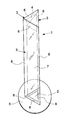
- the lighting device 1 consists of a light source 2, situated at the base of the lighting appliance 1, the structure of the lighting appliance 1 consisting of three side walls 3 and an upper wall 4, said walls all being made with a transparent material.
- the lighting device 1 rests with its side walls 3 on a base 5.
- a reflecting surface 6, which has the function of reflecting the beam of light, which would otherwise be dispersed upwards, in the direction considered most consonant.
- the side walls 3, the upper wall 4 and the base 5 define an internal space 7.
- the lighting appliance is particularly negatively influenced by the formation of condensate on the side walls 3.
- the formation of condensate on the reflecting surface 6 causes a reduction in its reflecting capacity
- the misting of the transparent surfaces of the side walls 3 causes a loss in their transparency and consequently an impoverishment of the lighting capacity of the lighting appliance 1.
- Creating and maintaining an inert atmosphere inside the lighting appliance 1 is particularly advantageous in this case.
- the present invention proposes filling the internal space 7 of the lighting device 1 with an inert and anhydrous gas 7. Furthermore, to prevent air and/or water (in the liquid state or as vapour) from subsequently entering the internal space (7) of the appliance, the edges of the internal space (7) are sealed with strips (8) of sealing adhesive, situated on the contact surfaces between the different components of the structure of the lighting appliance (1).
- the lighting appliance 1 is equipped with at least one valve element, through which the reintegrating gaseous stream is passed. This expedient is also necessary in cases in which it is not possible to ensure the perfect airtight-sealing of the lighting appliance 1, but the prevention of the development of life forms and condensate its interior is required.
- Gases which can be preferably used according to the present invention are nitrogen and argon.
- Nitrogen represents the most economically convenient solution (it can be obtained from the air by means of a fractionated distillation process), and is particularly suitable for preventing the development of aerobic life forms.
- argon is more expensive, it also prevents the development of anaerobic life forms, as well as guaranteeing a perfect non-interaction with the adhesives used for the sealing.
- the lighting appliance object of the present invention, has the advantage of providing an effective solution to the problems to be solved and of contemporaneously solving all problems relating to the development of life forms inside the lighting appliance 1, the formation of condensate on its surfaces, and also overpressures.
- the lighting appliance 1 maintains its lighting capacity with time, requiring sporadic and simple maintenance interventions.
- the lighting appliance according to the present invention provides a solution which is easy and economical to effect and manage.
- the forms, as also the materials, of the lighting appliance of the invention can differ from those shown for illustrative but non-limiting purposes in the figure.
Landscapes
- Engineering & Computer Science (AREA)
- General Engineering & Computer Science (AREA)
- Arrangement Of Elements, Cooling, Sealing, Or The Like Of Lighting Devices (AREA)
- Non-Portable Lighting Devices Or Systems Thereof (AREA)
Applications Claiming Priority (1)
| Application Number | Priority Date | Filing Date | Title |
|---|---|---|---|
| IT001399A ITMI20051399A1 (it) | 2005-07-21 | 2005-07-21 | Dispositivo di illuminazione |
Publications (2)
| Publication Number | Publication Date |
|---|---|
| EP1746342A2 true EP1746342A2 (de) | 2007-01-24 |
| EP1746342A3 EP1746342A3 (de) | 2007-02-21 |
Family
ID=36717010
Family Applications (1)
| Application Number | Title | Priority Date | Filing Date |
|---|---|---|---|
| EP06116537A Withdrawn EP1746342A3 (de) | 2005-07-21 | 2006-07-04 | Beleuchtungseinrichtung gefüllt mit einem wasserfreien und inerten Gas |
Country Status (4)
| Country | Link |
|---|---|
| EP (1) | EP1746342A3 (de) |
| CN (1) | CN1900582A (de) |
| IT (1) | ITMI20051399A1 (de) |
| NO (1) | NO20063336L (de) |
Family Cites Families (6)
| Publication number | Priority date | Publication date | Assignee | Title |
|---|---|---|---|---|
| AU3841372A (en) * | 1971-02-05 | 1973-08-02 | British Sealed Beams Limited | Sealed beam lamps |
| US3673424A (en) * | 1971-02-12 | 1972-06-27 | Nasa | Pressurized lighting system |
| FR2537249B1 (fr) * | 1982-12-02 | 1987-12-31 | Cibie Projecteurs | Projecteur a faisceau coupe a reflecteur elliptique pour vehicule automobile |
| US5128589A (en) * | 1990-10-15 | 1992-07-07 | General Electric Company | Heat removing means to remove heat from electric discharge lamp |
| US5692822A (en) * | 1995-11-29 | 1997-12-02 | Minnesota Mining & Manufacturing Co. | Uniform bi-directional dependent line light source via controlled partial reflection |
| US5743632A (en) * | 1996-11-12 | 1998-04-28 | The Genlyte Group Incorporated | Thermally controlled light fixture |
-
2005
- 2005-07-21 IT IT001399A patent/ITMI20051399A1/it unknown
-
2006
- 2006-07-04 EP EP06116537A patent/EP1746342A3/de not_active Withdrawn
- 2006-07-18 NO NO20063336A patent/NO20063336L/no not_active Application Discontinuation
- 2006-07-21 CN CNA2006101057430A patent/CN1900582A/zh active Pending
Also Published As
| Publication number | Publication date |
|---|---|
| ITMI20051399A1 (it) | 2007-01-22 |
| NO20063336L (no) | 2007-01-22 |
| EP1746342A3 (de) | 2007-02-21 |
| CN1900582A (zh) | 2007-01-24 |
Similar Documents
| Publication | Publication Date | Title |
|---|---|---|
| CA2822353C (en) | Compartmented temperature and humidity controlled modular housing for the storage and preservation of wine bottles | |
| EA030837B1 (ru) | Распорка для изолирующих остеклений | |
| BR0306990A (pt) | Válvula de esfera com gaxeta de peça única | |
| CA2593800A1 (en) | Improved venting system for minimizing condensation in a lighting assembly | |
| US20220057068A1 (en) | Dehumidifier for a closed vehicle headlamp housing | |
| DE60235333D1 (de) | Durchlässige Haube | |
| WO2020164359A1 (zh) | 显示装置和显示设备 | |
| EP1746342A2 (de) | Beleuchtungseinrichtung gefüllt mit einem wasserfreien und inerten Gas | |
| US20080048541A1 (en) | Polymer-thermal shield for ultra-violet lamp | |
| BR0300832A (pt) | Gabinete de refrigerador isolado à vácuo, e, método para evacuar um recipiente substancialmente estanque a gás | |
| JP6470076B2 (ja) | 炊飯器 | |
| US11192063B2 (en) | Apparatus, method, and system for reducing moisture in LED lighting fixtures | |
| WO1999009867A1 (en) | Apparatus for preserving an exhibit | |
| ES2191832T3 (es) | Cierre ventilado. | |
| WO2005105161A3 (de) | Sterilbehälter | |
| ES2182043T3 (es) | Botella aislante. | |
| KR200303011Y1 (ko) | 이중 구조의 납골단지 | |
| US762178A (en) | Means for heat jacketing and screening. | |
| KR20010046650A (ko) | 문화재 전시용 밀폐형 진열장의 조습제 박스 설치구조 | |
| RU15489U1 (ru) | Клееный стеклопакет | |
| EP1148111A3 (de) | Fluoreszenzdünnschicht, Herstellungsverfahren derselben,und elektrolumineszentes Paneel | |
| EP2606323B1 (de) | Spektroskopisches instrument | |
| CN211926280U (zh) | 储藏室及具有该储藏室的食物储存装置 | |
| AU2014201253B2 (en) | Light cover/diffuser for food cabinets | |
| JP2021066439A (ja) | ゲルパッキンシステム |
Legal Events
| Date | Code | Title | Description |
|---|---|---|---|
| PUAI | Public reference made under article 153(3) epc to a published international application that has entered the european phase |
Free format text: ORIGINAL CODE: 0009012 |
|
| PUAL | Search report despatched |
Free format text: ORIGINAL CODE: 0009013 |
|
| AK | Designated contracting states |
Kind code of ref document: A2 Designated state(s): AT BE BG CH CY CZ DE DK EE ES FI FR GB GR HU IE IS IT LI LT LU LV MC NL PL PT RO SE SI SK TR |
|
| AX | Request for extension of the european patent |
Extension state: AL BA HR MK YU |
|
| AK | Designated contracting states |
Kind code of ref document: A3 Designated state(s): AT BE BG CH CY CZ DE DK EE ES FI FR GB GR HU IE IS IT LI LT LU LV MC NL PL PT RO SE SI SK TR |
|
| AX | Request for extension of the european patent |
Extension state: AL BA HR MK YU |
|
| 17P | Request for examination filed |
Effective date: 20070613 |
|
| 17Q | First examination report despatched |
Effective date: 20070726 |
|
| AKX | Designation fees paid |
Designated state(s): AT BE BG CH CY CZ DE DK EE ES FI FR GB GR HU IE IS IT LI LT LU LV MC NL PL PT RO SE SI SK TR |
|
| STAA | Information on the status of an ep patent application or granted ep patent |
Free format text: STATUS: THE APPLICATION IS DEEMED TO BE WITHDRAWN |
|
| 18D | Application deemed to be withdrawn |
Effective date: 20071206 |