EP1746349A2 - Gaszuführungs-Anordnung für Gasherde - Google Patents
Gaszuführungs-Anordnung für Gasherde Download PDFInfo
- Publication number
- EP1746349A2 EP1746349A2 EP05380196A EP05380196A EP1746349A2 EP 1746349 A2 EP1746349 A2 EP 1746349A2 EP 05380196 A EP05380196 A EP 05380196A EP 05380196 A EP05380196 A EP 05380196A EP 1746349 A2 EP1746349 A2 EP 1746349A2
- Authority
- EP
- European Patent Office
- Prior art keywords
- fuel
- burner
- combustible
- gas
- mentioned
- Prior art date
- Legal status (The legal status is an assumption and is not a legal conclusion. Google has not performed a legal analysis and makes no representation as to the accuracy of the status listed.)
- Withdrawn
Links
Images



Classifications
-
- F—MECHANICAL ENGINEERING; LIGHTING; HEATING; WEAPONS; BLASTING
- F23—COMBUSTION APPARATUS; COMBUSTION PROCESSES
- F23D—BURNERS
- F23D14/00—Burners for combustion of a gas, e.g. of a gas stored under pressure as a liquid
- F23D14/46—Details
- F23D14/62—Mixing devices; Mixing tubes
- F23D14/64—Mixing devices; Mixing tubes with injectors
-
- F—MECHANICAL ENGINEERING; LIGHTING; HEATING; WEAPONS; BLASTING
- F23—COMBUSTION APPARATUS; COMBUSTION PROCESSES
- F23N—REGULATING OR CONTROLLING COMBUSTION
- F23N5/00—Systems for controlling combustion
- F23N5/02—Systems for controlling combustion using devices responsive to thermal changes or to thermal expansion of a medium
- F23N5/10—Systems for controlling combustion using devices responsive to thermal changes or to thermal expansion of a medium using thermocouples
-
- F—MECHANICAL ENGINEERING; LIGHTING; HEATING; WEAPONS; BLASTING
- F24—HEATING; RANGES; VENTILATING
- F24C—DOMESTIC STOVES OR RANGES ; DETAILS OF DOMESTIC STOVES OR RANGES, OF GENERAL APPLICATION
- F24C3/00—Stoves or ranges for gaseous fuels
- F24C3/08—Arrangement or mounting of burners
- F24C3/085—Arrangement or mounting of burners on ranges
-
- F—MECHANICAL ENGINEERING; LIGHTING; HEATING; WEAPONS; BLASTING
- F23—COMBUSTION APPARATUS; COMBUSTION PROCESSES
- F23D—BURNERS
- F23D2900/00—Special features of, or arrangements for burners using fluid fuels or solid fuels suspended in a carrier gas
- F23D2900/00014—Pilot burners specially adapted for ignition of main burners in furnaces or gas turbines
Definitions
- the present invention refers to a feeding group intended to supply the mix of fuel and combustible to the burner of a gas kitchen or any other similar device.
- the purpose of the invention is to improve the calorific power of the mix, resulting in fuel saving and allowing in parallel the use of a lower gas pressure, which at the same time improves the safety characteristics of the installation, reducing the burner dimensions for the same calorific power.
- gas burners usually used in kitchens and similar finish the fuel feeding tubing at a chamber equipped with a perimeter alignment of small holes, placed in a radial arrangement, through which the gas is distributed uniform and where it mixes with combustible air.
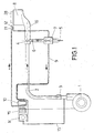
- the mentioned feeding group focuses its characteristics, one way, in the forced supply of the combustible, this means the air, by means of a blowing device as for example a motor-fan.
- the airflow mixes with the gas at a point substantially far from the burner, this means at a cold zone, far from the combustion point by means of the corresponding mixer, which improves the mix.
- the fuel/combustible mix circulates rotating at the cylinder zone of the burner, before reaching the combustion zone, that way turbulence in the mix is generated optimizing it and making it plainly homogeneous. In consequence, the combustion definitively improves.
- the fuel-combustible mix passes from the annular chamber defined in the cylindrical zone of the burner body to an axial chamber of the burner, through a diversity of slotted holes, so this axial chamber determines one only output hole, where the flame is produced.
- a stabilizing ring gear conveniently coupled to the burner cap frames the hole that fits the mouth of the burner body, which is determinant for the annular intermediate partition that separates the mentioned chambers.
- the structure described is complemented by a thermal insulation cone that fits the burner body which insulates it conveniently from the other group devices and from other burners that could exist, which receives a removable collar through the top mouth for supporting the container to be heated.
- a sample pressure (13) is set through a pressure gage (14), which at the same time controls the safety electro-valve (10), fed as the motor fan (1) from a group of electric connections (15).
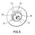
- the body (8) presents the top mouth staggered, for a tongue and groove connection of the cap (18) with a wide central hole (19), which extends as a bottom neck in which two sectors (20) and (21) of different diameter are defined, being this last one destined to connect to a hole (22) at the bottom of the body (8) and counting with a threaded sector (23) for its closure with the corresponding plug (24) threaded in correspondence.
- the collar Upon the cone mouth (29) the collar is connected tongued and grooved (31) which, with a considerable diameter, constitutes the supporting media for the containers to be heated.
Landscapes
- Engineering & Computer Science (AREA)
- Chemical & Material Sciences (AREA)
- Combustion & Propulsion (AREA)
- Mechanical Engineering (AREA)
- General Engineering & Computer Science (AREA)
- Gas Burners (AREA)
- Fluidized-Bed Combustion And Resonant Combustion (AREA)
Applications Claiming Priority (1)
| Application Number | Priority Date | Filing Date | Title |
|---|---|---|---|
| ES200501790A ES2300160B1 (es) | 2004-03-26 | 2005-07-21 | Mejoras introducidas en la patente de invencion p200400754 por grupo alimentador de combustible/comburente para cocinas de gas y similares. |
Publications (2)
| Publication Number | Publication Date |
|---|---|
| EP1746349A2 true EP1746349A2 (de) | 2007-01-24 |
| EP1746349A3 EP1746349A3 (de) | 2009-08-12 |
Family
ID=37401206
Family Applications (1)
| Application Number | Title | Priority Date | Filing Date |
|---|---|---|---|
| EP05380196A Withdrawn EP1746349A3 (de) | 2005-07-21 | 2005-09-13 | Gaszuführungs-Anordnung für Gasherde |
Country Status (1)
| Country | Link |
|---|---|
| EP (1) | EP1746349A3 (de) |
Cited By (5)
| Publication number | Priority date | Publication date | Assignee | Title |
|---|---|---|---|---|
| CN101737776B (zh) * | 2008-11-20 | 2012-05-30 | 广东万和新电气股份有限公司 | 家用燃气灶的预混合式燃烧器 |
| CN102889590A (zh) * | 2011-07-22 | 2013-01-23 | 佛山市启迪节能科技有限公司 | 一种全自动预混式燃烧器 |
| ES2426318R1 (es) * | 2012-04-20 | 2014-01-23 | BSH Electrodomésticos España S.A. | Quemador para un aparato de cocción calentado a gas |
| CN103615721A (zh) * | 2013-12-04 | 2014-03-05 | 南宁市鑫烽节能科技有限公司 | 燃气具的鼓风式全预混富氧装置 |
| FR3106388A1 (fr) | 2020-01-20 | 2021-07-23 | A.Raymond Et Cie | Dispositif de raccordement d’un élément tubulaire |
Family Cites Families (4)
| Publication number | Priority date | Publication date | Assignee | Title |
|---|---|---|---|---|
| US4827898A (en) * | 1988-05-19 | 1989-05-09 | Liao Wei Shiun | Gas stove burner |
| DE3918715A1 (de) * | 1989-05-13 | 1990-11-22 | Oedoen Gyoergy Dipl I Kuzselka | Gasbrenner mit konvergenter flamme fuer haushaltsherde (-kocher) und fuer aehnlichen anwendungen |
| GB2270750B (en) * | 1992-09-11 | 1996-08-14 | Stoves Ltd | Improvements in and relating to gas-fired cooking appliances |
| US6916175B2 (en) * | 2002-10-22 | 2005-07-12 | Kyungdong Boiler Co., Ltd. | Combustion gas burner enabling multi-stage control |
-
2005
- 2005-09-13 EP EP05380196A patent/EP1746349A3/de not_active Withdrawn
Cited By (8)
| Publication number | Priority date | Publication date | Assignee | Title |
|---|---|---|---|---|
| CN101737776B (zh) * | 2008-11-20 | 2012-05-30 | 广东万和新电气股份有限公司 | 家用燃气灶的预混合式燃烧器 |
| CN102889590A (zh) * | 2011-07-22 | 2013-01-23 | 佛山市启迪节能科技有限公司 | 一种全自动预混式燃烧器 |
| ES2426318R1 (es) * | 2012-04-20 | 2014-01-23 | BSH Electrodomésticos España S.A. | Quemador para un aparato de cocción calentado a gas |
| CN103615721A (zh) * | 2013-12-04 | 2014-03-05 | 南宁市鑫烽节能科技有限公司 | 燃气具的鼓风式全预混富氧装置 |
| CN103615721B (zh) * | 2013-12-04 | 2016-06-01 | 南宁市鑫烽节能科技有限公司 | 燃气具的鼓风式全预混富氧装置 |
| FR3106388A1 (fr) | 2020-01-20 | 2021-07-23 | A.Raymond Et Cie | Dispositif de raccordement d’un élément tubulaire |
| WO2021148737A1 (fr) | 2020-01-20 | 2021-07-29 | A. Raymond Et Cie | Dispositif de raccordement d'un élément tubulaire |
| US12072048B2 (en) | 2020-01-20 | 2024-08-27 | A. Raymond Et Cie | Device for connecting a tubular element |
Also Published As
| Publication number | Publication date |
|---|---|
| EP1746349A3 (de) | 2009-08-12 |
Similar Documents
| Publication | Publication Date | Title |
|---|---|---|
| CN102317684B (zh) | 气体燃烧器 | |
| EP2122248B1 (de) | Gasbrennersystem für kochgeräte | |
| CN101883952B (zh) | 具有改进的初级空气道的燃气燃烧器 | |
| KR101570358B1 (ko) | 조리용 가스버너 | |
| MX2012014726A (es) | Quemador de gas con flama orientada hacia dentro. | |
| US11493203B2 (en) | Gas burner assembly and gas cooking appliance comprising at least one gas burner assembly | |
| CN104110680A (zh) | 燃气炉头及燃气炉灶 | |
| CA3046916C (en) | Waste gas combustor with secondary air control and liquid containment/vaporization chamber | |
| CN109154437B (zh) | 燃气燃烧器和家用炊具 | |
| RU2425288C1 (ru) | Газовая горелка для варочной панели | |
| EP3393251B1 (de) | Ofen | |
| WO2014049421A1 (en) | Method for regulating the heating power of a gas burner, and an improved gas burner which uses the method | |
| CN112161268A (zh) | 一种炉头和燃烧器和燃气灶 | |
| CN103180088A (zh) | 气体螺栓加热装置 | |
| CN211040960U (zh) | 一种混合腔中置的完全上进风燃烧器 | |
| US11460190B2 (en) | Gas burner assembly for a cooktop appliance | |
| CN215336313U (zh) | 一种炉头和燃烧器和燃气灶 | |
| CN203963930U (zh) | 燃气炉头及燃气炉灶 | |
| CN110869672A (zh) | 燃气燃烧器以及包括燃气燃烧器的灶具 | |
| CN210267212U (zh) | 一种双环火灶具燃烧器 | |
| KR20200041539A (ko) | 고화력 가스버너 | |
| CN104033932B (zh) | 液体燃料炉头 | |
| WO2021006830A1 (en) | A burner assembly with radial outward flame | |
| CN106838903A (zh) | 一种设置预混腔的灶具燃烧器 | |
| KR20160027259A (ko) | 에너지 절략형 가스레인지의 가스유도용 더블캡 어셈블이 |
Legal Events
| Date | Code | Title | Description |
|---|---|---|---|
| PUAI | Public reference made under article 153(3) epc to a published international application that has entered the european phase |
Free format text: ORIGINAL CODE: 0009012 |
|
| AK | Designated contracting states |
Kind code of ref document: A2 Designated state(s): AT BE BG CH CY CZ DE DK EE ES FI FR GB GR HU IE IS IT LI LT LU LV MC NL PL PT RO SE SI SK TR |
|
| AX | Request for extension of the european patent |
Extension state: AL BA HR MK YU |
|
| RIC1 | Information provided on ipc code assigned before grant |
Ipc: F23D 14/34 20060101ALI20090404BHEP Ipc: F23D 14/08 20060101ALI20090404BHEP Ipc: F23D 14/06 20060101ALI20090404BHEP Ipc: F23D 14/00 20060101ALI20090404BHEP Ipc: F24C 3/08 20060101AFI20061123BHEP |
|
| PUAL | Search report despatched |
Free format text: ORIGINAL CODE: 0009013 |
|
| AK | Designated contracting states |
Kind code of ref document: A3 Designated state(s): AT BE BG CH CY CZ DE DK EE ES FI FR GB GR HU IE IS IT LI LT LU LV MC NL PL PT RO SE SI SK TR |
|
| AX | Request for extension of the european patent |
Extension state: AL BA HR MK YU |
|
| AKX | Designation fees paid | ||
| REG | Reference to a national code |
Ref country code: DE Ref legal event code: 8566 |
|
| STAA | Information on the status of an ep patent application or granted ep patent |
Free format text: STATUS: THE APPLICATION IS DEEMED TO BE WITHDRAWN |
|
| 18D | Application deemed to be withdrawn |
Effective date: 20100213 |