EP1746486A1 - Verfahren zur Bewegungsmeldung einer Einheit, die mit einem Bildsensor versehen ist, und Vorrichtung zur Umsetzung dieses Verfahrens - Google Patents
Verfahren zur Bewegungsmeldung einer Einheit, die mit einem Bildsensor versehen ist, und Vorrichtung zur Umsetzung dieses Verfahrens Download PDFInfo
- Publication number
- EP1746486A1 EP1746486A1 EP06291105A EP06291105A EP1746486A1 EP 1746486 A1 EP1746486 A1 EP 1746486A1 EP 06291105 A EP06291105 A EP 06291105A EP 06291105 A EP06291105 A EP 06291105A EP 1746486 A1 EP1746486 A1 EP 1746486A1
- Authority
- EP
- European Patent Office
- Prior art keywords
- image
- motion vector
- vector
- temporary
- reference data
- Prior art date
- Legal status (The legal status is an assumption and is not a legal conclusion. Google has not performed a legal analysis and makes no representation as to the accuracy of the status listed.)
- Granted
Links
Images


Classifications
-
- G—PHYSICS
- G06—COMPUTING OR CALCULATING; COUNTING
- G06F—ELECTRIC DIGITAL DATA PROCESSING
- G06F3/00—Input arrangements for transferring data to be processed into a form capable of being handled by the computer; Output arrangements for transferring data from processing unit to output unit, e.g. interface arrangements
- G06F3/01—Input arrangements or combined input and output arrangements for interaction between user and computer
- G06F3/03—Arrangements for converting the position or the displacement of a member into a coded form
- G06F3/0304—Detection arrangements using opto-electronic means
- G06F3/0317—Detection arrangements using opto-electronic means in co-operation with a patterned surface, e.g. absolute position or relative movement detection for an optical mouse or pen positioned with respect to a coded surface
-
- G—PHYSICS
- G06—COMPUTING OR CALCULATING; COUNTING
- G06F—ELECTRIC DIGITAL DATA PROCESSING
- G06F3/00—Input arrangements for transferring data to be processed into a form capable of being handled by the computer; Output arrangements for transferring data from processing unit to output unit, e.g. interface arrangements
- G06F3/01—Input arrangements or combined input and output arrangements for interaction between user and computer
- G06F3/03—Arrangements for converting the position or the displacement of a member into a coded form
- G06F3/033—Pointing devices displaced or positioned by the user, e.g. mice, trackballs, pens or joysticks; Accessories therefor
- G06F3/0354—Pointing devices displaced or positioned by the user, e.g. mice, trackballs, pens or joysticks; Accessories therefor with detection of two-dimensional [2D] relative movements between the device, or an operating part thereof, and a plane or surface, e.g. 2D mice, trackballs, pens or pucks
- G06F3/03543—Mice or pucks
-
- G—PHYSICS
- G06—COMPUTING OR CALCULATING; COUNTING
- G06T—IMAGE DATA PROCESSING OR GENERATION, IN GENERAL
- G06T7/00—Image analysis
- G06T7/20—Analysis of motion
- G06T7/223—Analysis of motion using block-matching
Definitions
- the present invention relates to motion estimation methods adapted to process a sequence of images provided, directly or indirectly, by a moving image sensor, for example to detect the movement of an entity provided with this sensor. images.
- the present invention is particularly suitable for an optical mouse connected to a computer in computer systems.
- Such image processing aims to detect mouse movements in order to retranscribe them in the form of a cursor movement on a computer screen.
- the movement of the optical mouse is generally detected on the basis of information captured by a video sensor or other type of sensor that is attached to the optical mouse.
- Such sensors provide a digital signal in the form of a sequence of images captured during the movement of the mouse. This digital signal is then processed in order to deduce the movement of the mouse.
- the mouse is moved to a suitable surface and the video sensor attached to the mouse captures images of that surface as it moves.
- the movement of the mouse can then be reconstructed from the relative positions of objects in the successive captured images.
- Such a method makes it possible to estimate the movement of a given block of pixels between two images that follow each other.
- these methods are based on an association of a motion vector with each of the processed images.
- a motion vector has a vertical component and a horizontal component. It represents the movement of the mouse from one image to another.
- the movement of all the pixels of each image to be processed can be represented by a single motion vector.
- This type of device is subject to specific technical constraints, such as in particular a time constraint. Indeed, the processing of such images must be done in a very short time so that the movement of the mouse can be retranscribed on the screen of the computer almost instantaneously for the user. Another very important constraint of this type of device is the cost of production.
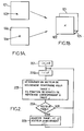
- FIG. 1-A and 1-B illustrate a definition of a motion vector.
- a sequence of two images is represented, a first image 101 is followed by a second image 102.
- the detection of movement of the mouse is based on the relative position of certain markers included in the different captured images.
- the image 101 comprises a marker in position 103 and the image 102 comprises the same marker in position 104. Thus, it is deduced the displacement of the optical mouse from its position relative to this marker.
- FIG. 1-B the images 101 and 102 are superimposed so that the respective positions of the marker coincide.
- the motion vector corresponding to the movement of the mouse in this context is represented by the arrow 105. Its components along the horizontal and the vertical X and Y.
- the movement of the mouse between the image 101 and the image 102 can be represented in the following by the motion vector 105. It is thus possible to associate the motion vector 105 with the image 101. which makes it possible to find the position of the mouse in the following image 102.
- motion vectors previously associated with previously processed images in the captured image sequence are generally based on by the mouse. Then, from such motion vectors, candidate vectors are generated, that is to say vectors which are capable of representing the movement of the mouse between two successive processed images. Then, relative to these candidate vectors, mouse position correlation calculations are performed, examples of which are well known to those skilled in the art. The candidate vector for which the greatest correlation is calculated is then selected. The latter is then associated with the current image.
- processed image refers to images to which a motion vector has been associated.
- a correlation calculation relating to a motion vector is based on a comparison of the pixel values of a block of pixels in a given image with the pixel values pointed in the next image by the motion vector associated with the image given from the pixels of the block of pixels of the given image.
- Digital images of more or less good quality can be obtained depending on the image processing methods used.
- a bilinear interpolation method of pixels is thus known.
- Such a method based on relatively simple mathematical calculations, makes it possible to obtain a certain quality of the image at an acceptable cost.
- a motion estimation method applied to such images may diverge in some conditions. In particular, when the mouse moves slowly compared to the speed of captured images.
- the present invention aims to provide an alternative to these known methods.
- a motion vector is determined as a function of data relating to a previous image in the image sequence, these data then being considered as reference data and being used to determine a vector. movement corresponding to the current image.
- Such a step corresponds to step / a / of a method according to the present invention.
- the method according to the present invention can advantageously be applied regardless of the method used in step / a / to determine a motion vector corresponding to a current image.
- a temporary motion vector checks the reliability criterion if its norm is greater than a threshold value.
- a temporary motion vector determined in relation to a current image does not have a norm greater than the threshold value, it is not associated with this current image. In this way, it is not taken into account in the rest of the motion estimation process. This eliminates motion vectors that could cause the process to diverge.
- the reference data comprise, on the one hand, a motion vector associated with a previous image and, on the other hand, the previous image.
- steps / a / and / b / are performed relative to a current image following the previous current image in the image sequence as a function of reference data corresponding to the previous current image.
- a direction of a first and second search vectors may be horizontal, and a direction of a third and a fourth search vectors may be vertical; the first and second search vectors on the one hand, and the third and fourth search vectors on the other hand, being of opposite respective meanings.
- an amplitude of the search vectors corresponding to the first iteration of step / 1 / is determined by selecting the largest value from a given threshold value, a horizontal component divided by two and a divided vertical component. by two of the motion vector associated with the previous processed image.
- An amplitude of the search vectors corresponding to a repetition of step / 1 / can be determined by selecting the largest value from a given threshold value, a horizontal component divided by two and a vertical component divided by two of the search vector corresponding to the motion vector selected at step / 2 / preceding step / 1 /.
- the selection rule applied in step / 2 / is based on a correlation calculation of a first block of pixels in the image being processed and a second block of pixels in the previous processed image from from which the candidate vector points to the first block of pixels, the candidate vector having the highest correlation being selected.
- the set of motion vectors from which the reference motion vector is selected for the first iteration of step / 1 / may further comprise the null vector.
- the control unit may decide that the temporary motion vector verifies the reliability criterion if a norm of the temporary motion vector is greater than a threshold value.
- the reference data selection unit is adapted to select reference data including the image and the associated motion vector and to provide such selected reference data to the determining unit after each data storage. in the memory.
- this information is supplied to the determination unit which also receives, in this case, a new current image from the image selection unit.
- the image selection unit is preferably adapted to select the image according to the previous selected image.
- a third aspect of the present invention provides an optical mouse comprising a moving image sensor adapted to cooperate with a motion estimation device according to the second aspect of the present invention.
- a fourth aspect of the present invention proposes a product "computer program” loadable directly into the internal memory a digital computer, comprising portions of software code for performing the steps of the method according to the first aspect of the present invention.
- the present invention is more particularly described in its application to optical mice. Of course, it is easy to deduce an application to any system in which an image sequence processing is applied to detect movements of a moving sensor with respect to the surface on which it moves.
- Figure 2 illustrates the main steps of a motion estimation method according to an embodiment of the present invention.
- the images of the sequence picked up by the optical mouse are referenced by indexes increasing according to the order of these images within the sequence.
- indices i and j are initialized to 0, i representing the index of the current image and j representing the index of the image corresponding to the reference data according to which a vector of temporary movement to associate with the indexed image i.
- reference data corresponding to a given image comprise the given image, that is to say the value of the pixels of this image, as well as the motion vector associated with it.
- the index i is incremented, the current image is thus the indexed image 1.
- a temporary motion vector is determined relative to the indexed image 1. This step is thus performed based on reference data corresponding to the indexed image 0.
- the invention covers any method or method for determining such a motion vector on the basis of these reference data and the indexed image 1.
- the temporary motion vector thus determined is controlled according to a reliability criterion. If this vector does not check such a criterion, the steps 202 and 203 are then repeated. For this purpose, the index of the current image is incremented, thus the indexed image 2 is considered, without incrementing the index of the image corresponding to the reference data according to which a temporary motion vector is determined.
- a temporary motion vector is determined relative to the indexed image 2 based on the reference data corresponding to the index image 0.
- Such a method therefore aims to increase the standard of the temporary motion vector to be associated with an image being processed.
- This method has all the more advantages as the speed of the image sequence is high compared to the movement of the mouse. Indeed, in such a case, when the mouse moves in the same direction, between two consecutive images of the sequence, the temporary motion vector determined in step / a / may have a low standard, and the images considered are far from each other, the norm of such a vector increases.
- the reliability of the determined temporary motion vector relative to the indexed image 2 is checked as a function of the reference data corresponding to the indexed image 0.
- Steps 202 and 203 are then repeated, by incrementing the index of the image being processed, but without incrementing the index of the previous image to which the reference data correspond, until it is determined a temporary motion vector verifying this reliability criterion.
- a temporary motion vector verifies a reliability criterion if its norm is greater than a threshold value.
- This threshold value may advantageously be a configuration value. Such a threshold value can then be adjusted depending in particular on the digital quality of the images of the captured image sequence.
- this vector is associated with the indexed image p at a step 205 .
- the indexed image p + 1 is then considered as a function of the reference data corresponding to the indexed image p.
- Figure 3 illustrates an application of a method according to an embodiment of the present invention. This figure illustrates a case in which the mouse is moved slowly with respect to the speed of images of the captured image sequence. This is the case when the mouse moves 1 ⁇ 4 pixel between two consecutive frames of the sequence.
- An array successively represents the indexes of images of the captured image sequence that are successively processed as a current image by a method according to an embodiment of the present invention.
- a table 32 represents the indexes of the images corresponding to the reference data respectively used to successively process the images of the sequence of images listed in Table 31.
- a table 33 represents the norm of the temporary motion vectors determined respectively for the current images whose index is in table 31 according to the reference data corresponding to the respective images whose indexes are listed in table 32.
- the norm is here expressed in 1/32 pixel.
- a temporary motion vector satisfies a reliability criterion if the norm of the vector is greater than or equal to the pixel.
- the indexed current image 1 is determined according to corresponding reference data.
- a temporary motion vector of norm equal to 8/32 pixels. Such a vector does not satisfy the criterion of reliability as stated above.
- step 203 is repeated with respect to the indexed image 2 based on the same reference data as before, i.e. those corresponding to the indexed image 0.
- the temporary motion vector then obtained has a standard of 16/32 pixels. The latter does not check the criterion of reliability either.
- Step 203 is therefore repeated with respect to the indexed image 3, and this always according to the same reference data.
- a 24/32 pixel standard motion vector is determined which still does not satisfy the reliability criterion.
- step 203 is repeated relative to the indexed image 4 as a function of the same reference data as before, a temporary motion vector of 1 pixel is determined which, in turn, verifies the criterion of reliability.
- This vector is then associated with the indexed image 4, as stated in step 205.
- reference data corresponding to the image to which a motion vector has just been associated is then based on the indexed image. 4.
- steps similar to those just described are performed relatively and successively to the indexed images 5 to 8 according to reference data corresponding to the indexed image 4.
- a temporary motion vector is then determined which verifies the criterion of reliability between the indexed image 4 and the indexed image 8.
- the indexed image 8 is associated with this motion vector.
- the indexed images 9 to 12 are successively processed with respect to reference data corresponding to the indexed image 8, to which a motion vector has just been associated.
- a temporary motion vector that determines the criterion is determined reliability of the indexed image 12. This motion vector is then associated with this last image.
- a temporary motion vector is determined which verifies the reliability criterion with respect to the indexed image 16. This motion vector is then associated with this last image.
- Table 34 represents the values of motion vectors stored in memory and intended to be read by a display function adapted to transcribe the movement of the mouse thus detected in the form of a movement of a cursor on the screen. 'a computer. Note that only the temporary motion vectors verifying the reliability criterion are advantageously stored. By such storage, the display function can read this data asynchronously.
- the method is simple and quick to implement and makes it possible to select a reliable motion vector for the images of the sequence of images captured by a mouse.
- Figure 4 illustrates the steps that are implemented to determine a temporary motion vector in step / a / of a motion detection method according to an embodiment of the present invention.
- an initial reference motion vector is first selected from a set of motion vectors.
- this set comprises the vector of null components as well as the motion vector associated with the image previously processed in the sequence of captured images. Then, the initial reference vector is selected according to a rule that will be detailed later.
- step 41 the method is initialized with an initial reference vector and an index x is initialized to 0.
- step 42 the index x is incremented by one unit.
- k candidate vectors are generated, where k is an integer strictly greater than 1.
- These candidate vectors are generated by adding to the initial reference vector respectively k search vectors. Two of these vectors can be of horizontal direction and respective opposite directions, while the other two are respectively vertical direction and opposite direction. These k search vectors can therefore be advantageously four in number. But one can have less or more in directions other than vertical and horizontal.
- step 44 a motion vector is selected from the candidate vectors thus generated. Such a selection can be made on the basis of various criteria which will be described later.
- steps 42, 43 and 44 are performed m + 1 times, m being an integer greater than 1.
- step 45 the value of the index x is compared with the value m. In the case where x is less than m, steps 42 to 45 are performed again.
- the reference motion vector is the motion vector selected in step 44 that has just been performed.
- step 203 was performed.
- the present invention covers any other method for determining a temporary motion vector.
- All or part of these associated motion vectors can be stored in a memory. They can thus be read, asynchronously, by a display function which is based on these vectors to move a symbol (for example a cursor) on a computer screen whose movement then follows the movement of the optical mouse.
- a display function which is based on these vectors to move a symbol (for example a cursor) on a computer screen whose movement then follows the movement of the optical mouse.
- Fig. 5 illustrates a step for obtaining an initial reference vector in a method according to an embodiment.
- the image being processed is the indexed image n, the image previously processed being the indexed image n-1.
- the previous processed image may not be the previous image in the captured image sequence. Indeed, under certain conditions, it may be advantageous not to process all the captured images of the image sequence.
- the captured images comprise a number N of pixels each, this number possibly being equal to 400, for example for an image of a size of 20 pixels by 20 pixels.
- the set of motion vectors from which an initial reference motion vector is selected comprises the null vector and the motion vector associated with the previous processed image. It should be noted here that it is possible to adapt such a method to a set of vectors comprising a larger number of motion vectors.
- a block of pixels is defined within the N pixels representing the n-1 image, and the following steps are applied to the pixels of this block of pixels.
- a block of pixels of 14 pixels by 14 pixels can be considered.
- step 501 the N pixels of the n-1 image previously processed, and the motion vector associated with this image are stored in memory.
- step 502 the null vector is applied to the block of pixels defined in the image n-1 and a correlation calculation is carried out between the value of the pixels of the block of pixels of the image n-1 and the value of the pixels. pixels of the corresponding dotted pixel block in image n. For this purpose, it is possible, for example, for each of the pixels of the window, to calculate the difference between the value of this pixel and the value of the pixel pointed by the null vector in the image n. The absolute values of the differences thus obtained are then summed and a first correlation result is obtained.
- the result of this correlation is then weighted by a value, which is preferably a configuration value, before being stored in memory.
- a weighting is of course optional and aims at improving the accuracy of such a method.
- a weighting value can be advantageously determined according to the speed of the images in the captured image sequence.
- step 504 the motion vector already associated with this image is applied to the block of pixels considered in the n-1 image.
- a correlation calculation is then performed. For this purpose, for each of the pixels of the block of pixels considered in the n-1 image, the difference between the value of a given pixel of the image n-1 and the value of the corresponding pixel in the image n, that is to say the pixel of the image n pointed from the pixel given by the motion vector associated with the image n-1.
- steps 502 and 504 can be performed in any order.
- the first and second correlation results are compared, and on the basis of this comparison, one selects from among the null vector and the motion vector associated with the n-1 image, the vector which allows 'get the greatest correlation.
- FIG. 6 illustrates, with the aid of the vectors represented, various steps of a method according to an embodiment of the present invention.
- This vector representation is made on a grid of squares which each have sides of a length corresponding to a fraction of a pixel. Such a length may for example be equal to 1/32 th of the length of a pixel.
- a vector 401 represents the initial reference motion vector, from which the various steps of the method according to an embodiment as illustrated in FIG. 4 are applied.
- the vector 401 is the motion vector associated with the n-1 image. In the example described, it is considered that the value of m is equal to 2.
- the index i is equal to 1.
- step 403 in the example illustrated in FIG. candidate vectors from the reference motion vector 401, X ref and Y ref coordinates, respectively adding 4 search vectors.
- the first candidate vector is obtained by adding to the reference motion vector 401 a first zero vertical component search vector and a horizontal component determined according to at least one component of the initial reference motion vector.
- the invention covers any method for determining such a component as a function of at least one of the components of the reference motion vector.
- the fourth search vector 405 is then obtained.
- the threshold value is preferably taken into account for the determination of the components of the search vectors in order to improve the convergence of such a method.
- Step 404 is then performed to select a vector among these candidate vectors.
- a correlation calculation is performed for each of these candidate vectors.
- the candidate vector with the best correlation is then selected.
- the candidate vector V cand3 is selected.
- Step 402 and step 403 are repeated.
- the reference movement vector considered is advantageously the motion vector that has just been selected in the preceding step 404, that is to say the vector V cand3 .
- the coordinates of these search vectors can be determined in the same way as during the first iteration of this step. We then obtain the first search vector 409, the second search vector 407, the third search vector 406 and finally the fourth search vector 408.
- the candidate vectors obtained at the second iteration of step 403 respectively check equations (1), (2), (3) and (4) by considering the search vectors 409, 407, 406 and 408.
- the candidate vector with the highest correlation is selected.
- the motion vector V cand1 is thus selected.
- step 402 to 405 are reiterated one last time by considering as a reference motion vector the motion vector that has just been selected in step 404, V cand1 .
- the four search vectors 413, 411, 410 and 412 are obtained, as illustrated in FIG. 6.
- the four candidate vectors are then generated from the new reference motion vector and the corresponding search vectors which can be advantageously determined as previously described. Then, for the third time, the motion vector selection step 404 is carried out among these four candidate vectors. For this purpose, the same methods as those described above may be used with reference to the previous iterations of step 404.
- Fig. 7 illustrates an entity motion detecting device provided with a movable sensor, according to an embodiment of the present invention.
- Such a device comprises a temporary movement vector determination unit 704.
- This unit is adapted on the one hand to receive as input a current image, that is to say an image to be processed, and reference data and on the other hand to output a vector of temporary movement relative to the current image according to the input data.
- the temporary motion vector is determined based on the reference data, and the present invention covers any method for such determination.
- Such a device also comprises an image selection unit 705 adapted to select an image in the captured image sequence and provide it to the determination unit 704 as a current image.
- It also includes a reference data selection unit 701 adapted to select reference data from data stored in a memory 702.
- the data stored in such a memory is data relating to images of the sequence of images already processed, that is to say, to which a motion vector has already been associated.
- This device also comprises a control unit 703 adapted to receive a temporary motion vector provided by the determination unit. Depending on the result of such a control on the temporary motion vector, different operations are performed. Thus, if the temporary motion vector satisfies a reliability criterion, the current image is associated with the temporary motion vector, and this association is then stored in the memory 702. The current image then becomes an image processed by the method according to an embodiment of the present invention.
- the determination unit is able to determine, based on the same reference data as used in the previous determination of a temporary motion vector, a temporary motion vector relative to the image. currently selected.
- the image selection unit 705 selects the image which follows, in the image sequence, the current image previously considered.
- the reference data selection unit 701 does not select different reference data, which therefore does not provide new data to the determining unit 704.
- the image selection unit 705 selects the image which follows the image which has just been associated with a motion vector and the provides to the unit of determination.
- the reference data selection unit 701 selects from the memory 702 reference data corresponding to the image that has just been associated with a motion vector.
- the determining unit receiving as input these reference data selected by the selection unit 701 and the image selected by the selection unit 705, is able to determine a new temporary motion vector and provide it. to the control unit that processes it as described above.
- the image selection unit 705 successively selects the images of the image sequence.
- the reference data selection unit 701 selects the last image associated with a motion vector stored in the memory 702.
- the control unit decides that the temporary motion vector verifies the reliability criterion if a norm of the temporary motion vector is greater than a threshold value.
- the invention allows a more accurate motion estimation and therefore a better rendering of the movement of the optical mouse pointer on a screen, especially in the case of rapid movements of the mouse. It can advantageously be used in any motion estimation method. It can be implemented easily and at a reasonable cost.
Landscapes
- Engineering & Computer Science (AREA)
- Theoretical Computer Science (AREA)
- General Engineering & Computer Science (AREA)
- Physics & Mathematics (AREA)
- General Physics & Mathematics (AREA)
- Human Computer Interaction (AREA)
- Multimedia (AREA)
- Computer Vision & Pattern Recognition (AREA)
- Image Analysis (AREA)
- Studio Devices (AREA)
Applications Claiming Priority (1)
| Application Number | Priority Date | Filing Date | Title |
|---|---|---|---|
| FR0507169 | 2005-07-05 |
Publications (2)
| Publication Number | Publication Date |
|---|---|
| EP1746486A1 true EP1746486A1 (de) | 2007-01-24 |
| EP1746486B1 EP1746486B1 (de) | 2009-12-16 |
Family
ID=36087764
Family Applications (1)
| Application Number | Title | Priority Date | Filing Date |
|---|---|---|---|
| EP06291105A Not-in-force EP1746486B1 (de) | 2005-07-05 | 2006-07-04 | Verfahren zur Bewegungsmeldung einer Einheit, die mit einem Bildsensor versehen ist, und Vorrichtung zur Umsetzung dieses Verfahrens |
Country Status (3)
| Country | Link |
|---|---|
| US (1) | US8300015B2 (de) |
| EP (1) | EP1746486B1 (de) |
| DE (1) | DE602006011086D1 (de) |
Families Citing this family (8)
| Publication number | Priority date | Publication date | Assignee | Title |
|---|---|---|---|---|
| US8179967B2 (en) * | 2005-07-05 | 2012-05-15 | Stmicroelectronics S.A. | Method and device for detecting movement of an entity provided with an image sensor |
| EP1998288A1 (de) * | 2007-05-31 | 2008-12-03 | Stmicroelectronics Sa | Verfahren zur Bewegungsbestimmung einer Einheit, die mit einem Bildsequenzsensor ausgestattet ist, sowie entsprechendes Computerprogramm, Modul und optische Maus |
| US8141473B2 (en) | 2009-03-18 | 2012-03-27 | Alliant Techsystems Inc. | Apparatus for synthetic weapon stabilization and firing |
| US8624998B2 (en) * | 2009-06-05 | 2014-01-07 | Apple Inc. | Camera image selection based on detected device movement |
| US8289400B2 (en) | 2009-06-05 | 2012-10-16 | Apple Inc. | Image capturing device having continuous image capture |
| JP2013041387A (ja) * | 2011-08-15 | 2013-02-28 | Sony Corp | 画像処理装置、画像処理方法、撮像装置、電子機器、及び、プログラム |
| JP6604998B2 (ja) * | 2017-07-20 | 2019-11-13 | キヤノン株式会社 | 画像処理装置、撮像装置、画像処理装置の制御方法およびプログラム |
| US10708501B2 (en) * | 2018-10-17 | 2020-07-07 | Sony Corporation | Prominent region detection in scenes from sequence of image frames |
Citations (4)
| Publication number | Priority date | Publication date | Assignee | Title |
|---|---|---|---|---|
| US6256016B1 (en) * | 1997-06-05 | 2001-07-03 | Logitech, Inc. | Optical detection system, device, and method utilizing optical matching |
| EP1283493A2 (de) * | 2001-07-30 | 2003-02-12 | Microsoft Corporation | Nachverfolgen der Bewegung eines Zeigegerätes unter Verwendung eines einzigen Pufferspeichers für Kreuz- und Autokorrelation |
| EP1361541A1 (de) * | 2002-04-09 | 2003-11-12 | STMicroelectronics S.r.l. | Verfahren und Vorrichtung zur globalen Bewegungsschätzung innerhalb einer Bildsequenz, z.B. für optische Mäuse |
| US20040100444A1 (en) * | 2002-11-22 | 2004-05-27 | Keun-Woo Park | Method of processing data of optical mouse |
Family Cites Families (9)
| Publication number | Priority date | Publication date | Assignee | Title |
|---|---|---|---|---|
| US4371895A (en) * | 1980-01-18 | 1983-02-01 | Nippon Electric Co., Ltd. | Coded video signal transmitting and receiving system |
| KR940010241B1 (ko) * | 1991-12-14 | 1994-10-22 | 산성전자 주식회사 | 이동 벡터 검출 방법 |
| US5578813A (en) * | 1995-03-02 | 1996-11-26 | Allen; Ross R. | Freehand image scanning device which compensates for non-linear movement |
| US7567617B2 (en) | 2003-09-07 | 2009-07-28 | Microsoft Corporation | Predicting motion vectors for fields of forward-predicted interlaced video frames |
| US7057148B2 (en) * | 2004-07-29 | 2006-06-06 | Ami Semiconductor, Inc. | Optical tracking sensor method |
| TWI243600B (en) | 2004-09-17 | 2005-11-11 | Primax Electronics Ltd | Selected area comparison method with high-operational efficient |
| US9172973B2 (en) | 2005-04-01 | 2015-10-27 | Broadcom Corporation | Method and system for motion estimation in a video encoder |
| US8179967B2 (en) | 2005-07-05 | 2012-05-15 | Stmicroelectronics S.A. | Method and device for detecting movement of an entity provided with an image sensor |
| US7965774B2 (en) | 2006-01-06 | 2011-06-21 | International Business Machines Corporation | Method for visual signal extrapolation or interpolation |
-
2006
- 2006-06-30 US US11/480,263 patent/US8300015B2/en active Active
- 2006-07-04 EP EP06291105A patent/EP1746486B1/de not_active Not-in-force
- 2006-07-04 DE DE602006011086T patent/DE602006011086D1/de active Active
Patent Citations (4)
| Publication number | Priority date | Publication date | Assignee | Title |
|---|---|---|---|---|
| US6256016B1 (en) * | 1997-06-05 | 2001-07-03 | Logitech, Inc. | Optical detection system, device, and method utilizing optical matching |
| EP1283493A2 (de) * | 2001-07-30 | 2003-02-12 | Microsoft Corporation | Nachverfolgen der Bewegung eines Zeigegerätes unter Verwendung eines einzigen Pufferspeichers für Kreuz- und Autokorrelation |
| EP1361541A1 (de) * | 2002-04-09 | 2003-11-12 | STMicroelectronics S.r.l. | Verfahren und Vorrichtung zur globalen Bewegungsschätzung innerhalb einer Bildsequenz, z.B. für optische Mäuse |
| US20040100444A1 (en) * | 2002-11-22 | 2004-05-27 | Keun-Woo Park | Method of processing data of optical mouse |
Also Published As
| Publication number | Publication date |
|---|---|
| EP1746486B1 (de) | 2009-12-16 |
| US20070040805A1 (en) | 2007-02-22 |
| DE602006011086D1 (de) | 2010-01-28 |
| US8300015B2 (en) | 2012-10-30 |
Similar Documents
| Publication | Publication Date | Title |
|---|---|---|
| EP2491532B1 (de) | Verfahren, computerprogramm, und vorrichtung für echtzeit-hybridverfolgung von objektdarstellungen in einer bildfolge | |
| EP2364490A1 (de) | Einrichtung mit datenstrom-pipeline-architektur zum erkennen und finden von objekten in einem bild durch detektionsfenster-scannen | |
| EP2930659B1 (de) | Verfahren zum erkennen von interessanten punkten in einem digitalen bild | |
| FR3112007A1 (fr) | Procédé et appareil d’entraînement de modèle, et procédé et appareil de prédiction | |
| EP3272119B1 (de) | Verfahren und anordnung zur 3d rekonstruktion einer szene | |
| WO2022207573A1 (fr) | Autoencodeur multimodal a fusion de donnees latente amelioree | |
| EP1746486B1 (de) | Verfahren zur Bewegungsmeldung einer Einheit, die mit einem Bildsensor versehen ist, und Vorrichtung zur Umsetzung dieses Verfahrens | |
| EP1998288A1 (de) | Verfahren zur Bewegungsbestimmung einer Einheit, die mit einem Bildsequenzsensor ausgestattet ist, sowie entsprechendes Computerprogramm, Modul und optische Maus | |
| WO2013156374A1 (fr) | Procede de reconnaissance d'un contexte visuel d'une image et dispositif correspondant | |
| EP0410826B1 (de) | Iteratives Bewegungsabschätzungsverfahren zwischen einem Referenzbild und einem aktuellen Bild, und Verfahren zu ihrer Herstellung | |
| EP1746487B1 (de) | Verfahren und Vorrichtung zur Bewegungsdetektion einer Einheit, die mit einem Bildsensor versehen ist | |
| EP1672585A1 (de) | Verfahren, Vorrichtung und System zur Verarbeitung von Bildern durch Bewegungsschätzung | |
| FR2933520A1 (fr) | Procede et dispositif de restauration d'une sequence video | |
| EP2943935B1 (de) | Schätzung der bewegung eines bildes | |
| EP3918576A1 (de) | Verfahren zur dynamischen dreidimensionalen bildgebung | |
| WO2019122664A1 (fr) | Procede d'amelioration du temps d'execution d'une application informatique | |
| BE1021546B1 (fr) | Procede et systeme pour le stockage de donnees de forme d'onde. | |
| EP1371958A1 (de) | Vorrichtung und Verfahren zum Extrahieren der spectralen Signatur eines punkförmigen Ziels | |
| WO2020001922A1 (fr) | Traitement d'un bruit impulsionnel dans une séquence vidéo | |
| FR2944937A1 (fr) | Procede et dispositif de restauration d'une sequence video | |
| Balure et al. | Guidance-based improved depth upsampling with better initial estimate | |
| FR3042292A1 (fr) | Procede d'optimisation de decomposition d'un signal asynchrone | |
| FR3153920A3 (fr) | Systèmes, méthodes et techniques d’apprentissage et d’utilisation d'attention creuse dépendant de l'instance pour transformateurs de vision efficaces | |
| FR3150891A1 (fr) | Procédé et dispositif de suivi de satellites dans une séquence d'images | |
| EP4150574A1 (de) | Verfahren zur verarbeitung von bildern |
Legal Events
| Date | Code | Title | Description |
|---|---|---|---|
| PUAI | Public reference made under article 153(3) epc to a published international application that has entered the european phase |
Free format text: ORIGINAL CODE: 0009012 |
|
| AK | Designated contracting states |
Kind code of ref document: A1 Designated state(s): AT BE BG CH CY CZ DE DK EE ES FI FR GB GR HU IE IS IT LI LT LU LV MC NL PL PT RO SE SI SK TR |
|
| AX | Request for extension of the european patent |
Extension state: AL BA HR MK YU |
|
| 17P | Request for examination filed |
Effective date: 20070720 |
|
| AKX | Designation fees paid |
Designated state(s): DE FR GB IT |
|
| 17Q | First examination report despatched |
Effective date: 20070910 |
|
| GRAP | Despatch of communication of intention to grant a patent |
Free format text: ORIGINAL CODE: EPIDOSNIGR1 |
|
| GRAS | Grant fee paid |
Free format text: ORIGINAL CODE: EPIDOSNIGR3 |
|
| GRAA | (expected) grant |
Free format text: ORIGINAL CODE: 0009210 |
|
| AK | Designated contracting states |
Kind code of ref document: B1 Designated state(s): DE FR GB IT |
|
| REG | Reference to a national code |
Ref country code: GB Ref legal event code: FG4D Free format text: NOT ENGLISH |
|
| REF | Corresponds to: |
Ref document number: 602006011086 Country of ref document: DE Date of ref document: 20100128 Kind code of ref document: P |
|
| PLBE | No opposition filed within time limit |
Free format text: ORIGINAL CODE: 0009261 |
|
| STAA | Information on the status of an ep patent application or granted ep patent |
Free format text: STATUS: NO OPPOSITION FILED WITHIN TIME LIMIT |
|
| 26N | No opposition filed |
Effective date: 20100917 |
|
| GBPC | Gb: european patent ceased through non-payment of renewal fee |
Effective date: 20100704 |
|
| PG25 | Lapsed in a contracting state [announced via postgrant information from national office to epo] |
Ref country code: IT Free format text: LAPSE BECAUSE OF FAILURE TO SUBMIT A TRANSLATION OF THE DESCRIPTION OR TO PAY THE FEE WITHIN THE PRESCRIBED TIME-LIMIT Effective date: 20091216 |
|
| REG | Reference to a national code |
Ref country code: FR Ref legal event code: ST Effective date: 20110331 |
|
| PG25 | Lapsed in a contracting state [announced via postgrant information from national office to epo] |
Ref country code: FR Free format text: LAPSE BECAUSE OF NON-PAYMENT OF DUE FEES Effective date: 20100802 |
|
| PG25 | Lapsed in a contracting state [announced via postgrant information from national office to epo] |
Ref country code: GB Free format text: LAPSE BECAUSE OF NON-PAYMENT OF DUE FEES Effective date: 20100704 |
|
| PGFP | Annual fee paid to national office [announced via postgrant information from national office to epo] |
Ref country code: DE Payment date: 20130621 Year of fee payment: 8 |
|
| REG | Reference to a national code |
Ref country code: DE Ref legal event code: R119 Ref document number: 602006011086 Country of ref document: DE |
|
| PG25 | Lapsed in a contracting state [announced via postgrant information from national office to epo] |
Ref country code: DE Free format text: LAPSE BECAUSE OF NON-PAYMENT OF DUE FEES Effective date: 20150203 |
|
| REG | Reference to a national code |
Ref country code: DE Ref legal event code: R119 Ref document number: 602006011086 Country of ref document: DE Effective date: 20150203 |