EP1746558A2 - System und Verfahren für die Simulation eines manuellen Eingriffes in einem medizinischen Verfahren. - Google Patents
System und Verfahren für die Simulation eines manuellen Eingriffes in einem medizinischen Verfahren. Download PDFInfo
- Publication number
- EP1746558A2 EP1746558A2 EP05291563A EP05291563A EP1746558A2 EP 1746558 A2 EP1746558 A2 EP 1746558A2 EP 05291563 A EP05291563 A EP 05291563A EP 05291563 A EP05291563 A EP 05291563A EP 1746558 A2 EP1746558 A2 EP 1746558A2
- Authority
- EP
- European Patent Office
- Prior art keywords
- real
- mesh
- simulating
- instrument
- user
- Prior art date
- Legal status (The legal status is an assumption and is not a legal conclusion. Google has not performed a legal analysis and makes no representation as to the accuracy of the status listed.)
- Granted
Links
- 238000000034 method Methods 0.000 title claims description 63
- 238000004088 simulation Methods 0.000 claims abstract description 37
- 230000005291 magnetic effect Effects 0.000 claims abstract description 13
- 238000003825 pressing Methods 0.000 claims abstract description 3
- 238000004422 calculation algorithm Methods 0.000 claims description 40
- 230000002792 vascular Effects 0.000 claims description 25
- 239000007788 liquid Substances 0.000 claims description 24
- 239000012530 fluid Substances 0.000 claims description 22
- 230000000747 cardiac effect Effects 0.000 claims description 17
- 238000012800 visualization Methods 0.000 claims description 15
- 208000031481 Pathologic Constriction Diseases 0.000 claims description 13
- 208000005392 Spasm Diseases 0.000 claims description 13
- 230000000694 effects Effects 0.000 claims description 13
- 230000036262 stenosis Effects 0.000 claims description 13
- 208000037804 stenosis Diseases 0.000 claims description 13
- 230000000704 physical effect Effects 0.000 claims description 9
- 210000004204 blood vessel Anatomy 0.000 claims description 7
- 230000009471 action Effects 0.000 claims description 6
- 238000002347 injection Methods 0.000 claims description 6
- 239000007924 injection Substances 0.000 claims description 6
- 238000003780 insertion Methods 0.000 claims description 6
- 230000037431 insertion Effects 0.000 claims description 6
- 210000003462 vein Anatomy 0.000 claims description 6
- 230000036772 blood pressure Effects 0.000 claims description 5
- 238000009792 diffusion process Methods 0.000 claims description 5
- 239000000696 magnetic material Substances 0.000 claims description 4
- 239000002245 particle Substances 0.000 claims description 4
- 238000013461 design Methods 0.000 claims description 3
- 230000000750 progressive effect Effects 0.000 claims description 3
- 241001465754 Metazoa Species 0.000 claims description 2
- 208000007101 Muscle Cramp Diseases 0.000 claims description 2
- 208000001871 Tachycardia Diseases 0.000 claims description 2
- 210000000748 cardiovascular system Anatomy 0.000 claims description 2
- 208000010125 myocardial infarction Diseases 0.000 claims description 2
- 238000005293 physical law Methods 0.000 claims description 2
- 230000006794 tachycardia Effects 0.000 claims description 2
- 230000033001 locomotion Effects 0.000 description 19
- 210000001367 artery Anatomy 0.000 description 15
- 230000003993 interaction Effects 0.000 description 14
- 238000005516 engineering process Methods 0.000 description 12
- 238000009877 rendering Methods 0.000 description 11
- 230000008901 benefit Effects 0.000 description 10
- 238000002594 fluoroscopy Methods 0.000 description 9
- 101150113144 CARTPT gene Proteins 0.000 description 8
- 239000008280 blood Substances 0.000 description 8
- 210000004369 blood Anatomy 0.000 description 8
- 230000008859 change Effects 0.000 description 8
- 230000006870 function Effects 0.000 description 8
- 210000003484 anatomy Anatomy 0.000 description 7
- 238000012360 testing method Methods 0.000 description 7
- 230000000007 visual effect Effects 0.000 description 7
- 238000004804 winding Methods 0.000 description 7
- 230000004913 activation Effects 0.000 description 6
- 230000006399 behavior Effects 0.000 description 6
- 238000004364 calculation method Methods 0.000 description 6
- 239000000463 material Substances 0.000 description 6
- 239000002184 metal Substances 0.000 description 6
- 229910052751 metal Inorganic materials 0.000 description 6
- 238000002224 dissection Methods 0.000 description 5
- 210000001519 tissue Anatomy 0.000 description 5
- 239000000872 buffer Substances 0.000 description 4
- 238000007667 floating Methods 0.000 description 4
- 230000000004 hemodynamic effect Effects 0.000 description 4
- 238000002156 mixing Methods 0.000 description 4
- 230000001105 regulatory effect Effects 0.000 description 4
- 230000004044 response Effects 0.000 description 4
- 238000010276 construction Methods 0.000 description 3
- 230000006378 damage Effects 0.000 description 3
- 230000003902 lesion Effects 0.000 description 3
- 238000007726 management method Methods 0.000 description 3
- 230000003287 optical effect Effects 0.000 description 3
- 230000008569 process Effects 0.000 description 3
- 238000012545 processing Methods 0.000 description 3
- 238000012549 training Methods 0.000 description 3
- XEEYBQQBJWHFJM-UHFFFAOYSA-N Iron Chemical compound [Fe] XEEYBQQBJWHFJM-UHFFFAOYSA-N 0.000 description 2
- 229910000831 Steel Inorganic materials 0.000 description 2
- 208000027418 Wounds and injury Diseases 0.000 description 2
- 230000001668 ameliorated effect Effects 0.000 description 2
- 238000004458 analytical method Methods 0.000 description 2
- 238000013459 approach Methods 0.000 description 2
- 230000017531 blood circulation Effects 0.000 description 2
- 239000003086 colorant Substances 0.000 description 2
- 230000009849 deactivation Effects 0.000 description 2
- 238000010586 diagram Methods 0.000 description 2
- 230000001965 increasing effect Effects 0.000 description 2
- 208000014674 injury Diseases 0.000 description 2
- 238000009434 installation Methods 0.000 description 2
- 230000002452 interceptive effect Effects 0.000 description 2
- 238000013507 mapping Methods 0.000 description 2
- 238000005259 measurement Methods 0.000 description 2
- 230000015654 memory Effects 0.000 description 2
- 238000005457 optimization Methods 0.000 description 2
- 210000000056 organ Anatomy 0.000 description 2
- 230000000737 periodic effect Effects 0.000 description 2
- 239000010959 steel Substances 0.000 description 2
- 230000001360 synchronised effect Effects 0.000 description 2
- 238000003325 tomography Methods 0.000 description 2
- 238000012546 transfer Methods 0.000 description 2
- 230000001131 transforming effect Effects 0.000 description 2
- 229910001006 Constantan Inorganic materials 0.000 description 1
- RYGMFSIKBFXOCR-UHFFFAOYSA-N Copper Chemical compound [Cu] RYGMFSIKBFXOCR-UHFFFAOYSA-N 0.000 description 1
- 230000002159 abnormal effect Effects 0.000 description 1
- 239000008186 active pharmaceutical agent Substances 0.000 description 1
- 230000003044 adaptive effect Effects 0.000 description 1
- 238000002583 angiography Methods 0.000 description 1
- 238000002399 angioplasty Methods 0.000 description 1
- 210000000709 aorta Anatomy 0.000 description 1
- 208000007474 aortic aneurysm Diseases 0.000 description 1
- 238000000149 argon plasma sintering Methods 0.000 description 1
- 238000005452 bending Methods 0.000 description 1
- 230000005540 biological transmission Effects 0.000 description 1
- 230000015572 biosynthetic process Effects 0.000 description 1
- 238000013276 bronchoscopy Methods 0.000 description 1
- 239000000969 carrier Substances 0.000 description 1
- 238000002052 colonoscopy Methods 0.000 description 1
- 238000012505 colouration Methods 0.000 description 1
- 238000012885 constant function Methods 0.000 description 1
- 230000008602 contraction Effects 0.000 description 1
- 239000002872 contrast media Substances 0.000 description 1
- 229910052802 copper Inorganic materials 0.000 description 1
- 239000010949 copper Substances 0.000 description 1
- 230000003247 decreasing effect Effects 0.000 description 1
- 230000000593 degrading effect Effects 0.000 description 1
- 230000001419 dependent effect Effects 0.000 description 1
- 238000001514 detection method Methods 0.000 description 1
- 238000011161 development Methods 0.000 description 1
- 238000012631 diagnostic technique Methods 0.000 description 1
- 239000006185 dispersion Substances 0.000 description 1
- 230000003073 embolic effect Effects 0.000 description 1
- 238000000605 extraction Methods 0.000 description 1
- 230000005294 ferromagnetic effect Effects 0.000 description 1
- 239000011888 foil Substances 0.000 description 1
- 239000012634 fragment Substances 0.000 description 1
- 238000002575 gastroscopy Methods 0.000 description 1
- 230000006872 improvement Effects 0.000 description 1
- 230000001939 inductive effect Effects 0.000 description 1
- 238000013152 interventional procedure Methods 0.000 description 1
- 229910052742 iron Inorganic materials 0.000 description 1
- 238000002357 laparoscopic surgery Methods 0.000 description 1
- 238000002576 laryngoscopy Methods 0.000 description 1
- 238000012886 linear function Methods 0.000 description 1
- 238000004519 manufacturing process Methods 0.000 description 1
- 238000013178 mathematical model Methods 0.000 description 1
- 239000011159 matrix material Substances 0.000 description 1
- 230000007246 mechanism Effects 0.000 description 1
- 239000007769 metal material Substances 0.000 description 1
- 210000003205 muscle Anatomy 0.000 description 1
- 230000001575 pathological effect Effects 0.000 description 1
- 230000002093 peripheral effect Effects 0.000 description 1
- 230000004962 physiological condition Effects 0.000 description 1
- 229920001721 polyimide Polymers 0.000 description 1
- 238000007781 pre-processing Methods 0.000 description 1
- 230000002685 pulmonary effect Effects 0.000 description 1
- 230000009467 reduction Effects 0.000 description 1
- 238000012827 research and development Methods 0.000 description 1
- 230000033764 rhythmic process Effects 0.000 description 1
- 239000000523 sample Substances 0.000 description 1
- 239000000243 solution Substances 0.000 description 1
- 238000001356 surgical procedure Methods 0.000 description 1
- 230000001839 systemic circulation Effects 0.000 description 1
- 230000009885 systemic effect Effects 0.000 description 1
- 230000008719 thickening Effects 0.000 description 1
- 238000011282 treatment Methods 0.000 description 1
Images


Classifications
-
- G—PHYSICS
- G09—EDUCATION; CRYPTOGRAPHY; DISPLAY; ADVERTISING; SEALS
- G09B—EDUCATIONAL OR DEMONSTRATION APPLIANCES; APPLIANCES FOR TEACHING, OR COMMUNICATING WITH, THE BLIND, DEAF OR MUTE; MODELS; PLANETARIA; GLOBES; MAPS; DIAGRAMS
- G09B23/00—Models for scientific, medical, or mathematical purposes, e.g. full-sized devices for demonstration purposes
- G09B23/28—Models for scientific, medical, or mathematical purposes, e.g. full-sized devices for demonstration purposes for medicine
- G09B23/30—Anatomical models
-
- G—PHYSICS
- G09—EDUCATION; CRYPTOGRAPHY; DISPLAY; ADVERTISING; SEALS
- G09B—EDUCATIONAL OR DEMONSTRATION APPLIANCES; APPLIANCES FOR TEACHING, OR COMMUNICATING WITH, THE BLIND, DEAF OR MUTE; MODELS; PLANETARIA; GLOBES; MAPS; DIAGRAMS
- G09B23/00—Models for scientific, medical, or mathematical purposes, e.g. full-sized devices for demonstration purposes
- G09B23/28—Models for scientific, medical, or mathematical purposes, e.g. full-sized devices for demonstration purposes for medicine
- G09B23/285—Models for scientific, medical, or mathematical purposes, e.g. full-sized devices for demonstration purposes for medicine for injections, endoscopy, bronchoscopy, sigmoidscopy, insertion of contraceptive devices or enemas
Definitions
- the present invention is related to a system and a method for simulating a manual interventional operation by a user in a medical procedure.
- the surgeon should direct a guide wire, a catheter and a sheath through arteries to a blockage point and inflate a balloon to withdraw the blockage.
- the prior art which has attempted to overcome the above described disadvantages of live patients to train physicians is basically disclosing (see for instance US 4,907,973 ) expert simulator system for modeling realistic internal environment having a mock tool such as an endoscope inserted and manipulated within a model.
- the model has a mock bodily region to be monitored and a plurality of sensors to detect the position of the tool (an endoscope) within the body.
- a computer is used for representing the views observed from the measured endoscope position during a real operation.
- a medical procedure simulation system that utilizes virtual reality technology.
- Such system includes a display device and programmable tactile/force reflecting mechanisms that provide force feedback to generate the feeling of medical instrument and the interaction of the instruments with a simulated anatomy.
- the present invention provides a system for simulating a manual interventional operation by a user on a simulated body with at least two real instruments, wherein said device comprises a longitudinal track, a plurality of moveable carriages along said track, each carriage having clamping means for securing one of said real instruments to said corresponding carriage, means for rotating and moving longitudinally said real instrument, visuals means, processing means for simulating a medical procedure and providing visual elements on said visual means and feed back means for receiving and transmitting to the user hand a feed back force from said real instrument with respect to simulation characteristic, characterised in that it comprises means for recognizing a real instrument to be fit within said clamping means, said clamping means comprising first electro-magnetic means with an hollow part for receiving the real instrument to be secured therein, second electro-magnetic means with a protruding part for pressing at least a part of said real instrument within said hollow part while said electromagnetic means are
- the first electro-magnetic means comprise a generally cylindrical block having a broader center part for receiving a solenoid and a longitudinal hollow channel for receiving said real instrument.
- the second electro-magnetic means comprise a block having a central protruding part, said block being provided with a central spine arranged to cooperate with the instrument when inserted in the longitudinal hollow.
- the generally cylindrical block comprises three parts connected together, i.e. a first part which is cylindrical and comprises a funnel or conical hollow element that authorises insertion of the guide of the tool by progressive guiding into an axial cylindrical channel provided inside said part in the prolongation of such conical entry, a parallelepipedic second part or central part integrally connected to the first part, forming said broader center part, made of magnetic material and arranged to cooperate with the second element, said central part including a central and axial prolongation of channel, which is half cylindrical on its inferior part and opened on its superior part such as the part presents a plane interconnecting superior surface with second element, on which is affixed the negative or positive pole of the electromagnet clamping means, and a third part, with a central channel in the prolongation of channels, symmetrical to first part with regard to the center part.
- a first part which is cylindrical and comprises a funnel or conical hollow element that authorises insertion of the guide of the tool by progressive guiding into an axial cylindrical channel provided inside said part in the
- the bloc having a central protruding part comprises a parallelepipedic element on which is affixed the positive or negative pole of the electromagnet clamping means.
- system further comprises two ball bearings, into which are inserted the elements for rotation around a central axis.
- the invention also provides a method of simulating an interventional operation on a human or animal body, said method comprising the steps of modelling the internal system such as the cardiovascular system of said body with a mesh geometry, while in the embodiment of the present invention particularly described here, using accurate clamping means as above described and/or simulating blood pressure, and/or collision with heart attacks and/or expansion produced during the cure of stenosis.
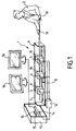
- Figure 1 shows a system 1 for simulating a manual interventional operation by a user 2 on a simulated body which could be materialized by a manikin (not represented), with three real instruments 3, 4, 5 such as for instance a guide wire, a catheter and a sheath, comprising a device 6 having a protecting casing 7, a longitudinal track 8, three movable identical carriages 9, 10, 11 along said track, each arranged for securing a corresponding instrument.
- Each carriage is respectively connected to an interface box 12 connected to a computer 13 having a processing unit 14, storing memories 15 and a set of two visual screens 16.
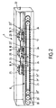
- Figure 2 shows more precisely in cross section and perspective the device 6 comprising the three carriages 9, 10, 11 having the same functionalities and which are similar or identical in the present embodiment.
- Each carriage comprises detecting means 17, for instance optical captors, for recognizing the presence of real instrument 3, 4, 5 to be fitted in, such as an endoscope, a catheter, etc.
- It also comprises feedback means 18, known per se, for receiving and transmitting to the user hands 19 (see figure 1) a feedback force from said real instrument with respect to the movement of the hand and of the simulation procedure stored in the memories 15 of the computer.
- feed back means are formed, for example is the following manner.
- the locking system is situated on a feedback control system member, held on by two metal leaves allowing feedback working in pulling and pushing.
- the feedback control system member response depends on the leaves' deformation, caused by the force applied on the locked tool.
- the deformation of the leaves has to determine a feedback control system member response so that the users feel a real tactile-feedback.
- the amount of leaves' deformation is proportional to the force applied by the user and has to be detected to be used in determining the feedback-response.
- the amplified signal is then sent to the electronic case that facilitates or contrasts the managing tool dedicated elements (tool wagon) movement, using a motor.
- the output voltage change is at least 10 mV with a voltage supply of ⁇ 2.5 V to be processed by the instrumentation amplifier.
- the leaves' thickness is chosen considering an excursion of the feedback control system member of maximum ⁇ 0.3 mm and considering a minimum leaves' thickness that could't permanently be deformed by the applied force.
- the measurement tests have been implemented using a strain indicator and recorder and a 3D control system:
- the core of the feedback control system is a deformation transducer that measures the deformation of an extensometer known per se for instance a transducer manufactured by the firm VISHAY or equivalent sited on one of the metal leaves changing output voltage. It was considered an open-faced constantan foil gages with a thin, laminated, polyimide-film backing. This gage is recommended for use in precision transducers and characterized by low and repeatable creep performance.
- the extensometer used is a compact full-bridge pattern for use on small, double-bending beams, axial grid centerline spacing 0.250 in (6.35 mm), resistance in ⁇ is 350 ⁇ 0.2% and gage self-temperature compensation, the approximate thermal expansion coefficient in ppm/°F of the structural material on which the gage is to be used, follow the characteristics shown on figure 7, where K-Allay (curb 65), A-Allay (curb 66) and D-Allay (curb 67) evaluate according to said curbs, with absciss in O and Thermal output in ue along the Y axis.
- Transducer's output voltage being used to control motors that, according to the impressed force, help the independent dedicated system's movement.
- the feedback of the device is for example obtained through an electronic card with two custom programmed pic of the series 16f876.
- control signals have been withdrawn from the electronic board : direction control, PWM-out, motor enable.
- the signals are sent to the 16f876 pic and managed by a feedback software of the type as follows (in picbasis).
- the software loaded on the 16f876 pic waits for the activation data of the feedback status sent by the PC. In these data there is the value of the gain constant of the derivative integrative proportional system that the feedback implements.
- a local retro-action starts.
- the local retro-action takes the digital value of the extensimeter - opportunely converted by the analogical digital converter of the pic 16f876 - as reference signal,.
- the device 1 further comprises motors 20, 20', 20" and transmission belts 21, 21', 21" for having the carriages moving on track 8, an entry 22 for introducing the elongated instruments in the device, and interconnecting elements 23, 23', 23'', for instance in the form of telescopic pipes 24, 24', 24'', for interconnecting the carriages and letting the elongated instruments go through freely.
- each carriage is connected to the interface box 12.
- each carriages further comprises clamping means 25 which shall now be more precisely described in reference to figures 3 and 4.
- Clamping means 25 provide a locking and rotating system which does not use motors.
- Opening and closing the clamp happen through electromagnets that are activated when the tool or elongated instrument is recognized by the detecting means 17.
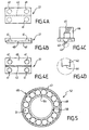
- the clamping means comprise two elements 26 (see figures 3A-3E) and 27 (see figures 4A-4D) (i.e. first electromagnetic means 26 and second electromagnetic means 27).
- FIG. 3A is a top view
- figure 3B a side view
- figure 3C a front view
- figure 3D a bottom view of element 26.
- Figure 3E is a cross section according to III E -III E of figure 3B.
- element 26 comprises three parts integrally connected together 28, 29, 30.
- a first part 28 which is cylindrical and comprises a funnel or conical hollow entry 31 that authorises a perfect insertion of the guide of the tool (not represented) by progressive guiding into an axial cylindrical channel 32 provided inside said part in the prolongation of such conical entry.
- the second part 29 or central part is integrally connected to the first part. It is parallelepipedic and arranged to cooperate with the second element 27.
- Such part includes a central and axial prolongation 33 of channel 32, which is half cylindrical on its inferior part and opened on its superior part such as the part 29 presents a plane interconnecting superior surface 34 with second element 27.
- Part 29 is made of magnetic material to form, when activated by adjacent wrapping coil 35 for instance fixed on a plastic U shape portion attached on the external inferior face of said part 29, (see figure 3C) the negative pole of the electromagnet clamping of the preferred embodiment of the invention described herewith.
- the wrapping coils 35 are provided in a manner which will be described hereafter.
- the superior face 34 has four cylindrical hollow cavities 37 disposed at each of the rectangle corners and containing heloicodal springs 38.
- Figures 4A-4D show details on element 27. More particularly figure 4A is a top view, figure 4B a side view and figure 4C a front view of element 27.
- Figure 4D shows a detail of figure 4C on the edge of the protruding part of element 27.
- element 27 is formed of magnetic material such as ferromagnetic iron to constitute the positive pole of the electromagnet to be obtained.
- element 27 is a parallelepipedic bloc of the same lateral and longitudinal dimensions or slightly smaller than second part 29 of element 26, so to slidably fit between lateral facing sides 39 respectively of parts 28 and 30.
- plane inferior face 40 arranged to cooperate with plane superior face 34 of element 26, and comprises four corresponding hollow cavities 41 identical to holes 37 for containing the other extremities of springs 38, such as, without any pressure between element 27 and part 29 the springs maintain at distance their respective superior and inferior surface.
- Element 27 further comprises a protruding longitudinal arrest or shelf 42 arranged to penetrate and slidably match with half cylindrical channel prolongation 33.
- This arrest presents on its longitudinal periphery summit or edge 43, a concave cylindrical wall 44 (see figure 4D), to shapily cooperate with the elongated tool (not represented).
- An adjacent coil 45 for instance fixed on a plastic U shape portion 46 attached on the external superior face of element 27, is provided.
- the force, with which the clamp is created can vary and change as instructed by the computer, as it depends on the current supplied to the magnetic system which is easily regulated in a manner known per se.
- the coils are provided within a system which both allows magnetic activation while authorizing a perfect and smooth rotation of the whole system along the axis of the carriages.
- two plastic cages 48 with two cylindrical walls 49, 50, in which balls 51 are inserted, are provided to form two ballbearings 52.
- the clamp per se i.e. elements 26 and 27, heart of the locking system, is inserted within these two bearings as it will be further described here after.
- coils are formed by solenoid with very thin windings of copper.
- the two elements are on their side realized in ultralight metallic material.
- element 26 is a unique block, with shape substantially of a cylinder on its end parts (28 and 30), and in which the center zone 29 has increased dimensions for the connection with solenoid 35.
- Elements 27 is on its part, traversed from its beginning to its end by channel 32-33, whose diameter depends on the maximum dimension of the tools that the clamp will have to block.
- channel 33 has then the same diameter than channel 32 when no activation of the clamp is performed.
- the two cylindrical parts 28 and 30 (of enter and exit of the tool) are on their part, covered, on their internal surface, by an oxidating layer that isolates them electrically from the magnetic action coming from the solenoid.
- element 27 is also made by a unique block, with a parallelepipedic shape provided with a protruding longitudinal arrest 42 of the same length than the whole element 27 and with a smaller width than the diameter of the channel 32 of element 26.
- the depth and shape section of such arrest on their part, are designated according to the locking of the different kinds of tools.
- the two cylindrical enter and exit parts 28 and 30 are inserted in the two ball bearings 52 and fixed in the internal walls 50 of the cages, so that the entire block of the clamp can rotate about the axis of the channel 32.
- the electrical contact created on the income wall is connected with the windings of the solenoid 35 interlocked to element 26, while the one on the exit wall with the windings of the solenoid 45 is interlocked to element 27.
- the external metal rings of the bearings are fixed to the corresponding walls, and are electrically connected with the walls, and also with the inner metal rings, through the spheres of the bearing.
- the cage is itself interlocked to the plain base (not represented) of the corresponding carriage which has the possibility to move along the axis of the channel 32 within the casing 7.
- Elements 26 and 27 are joined together through four springs, placed in the holes 37 and 41 of the central zone.
- the arrest 42 of element 27 is inserted in the channel 32 of element 26, in order to guide the movement of element 27 in orthogonal direction to the axis of holes 37 and 41.
- element 27 In rest state, i.e. when the tool still has not been recognized from the Presence System, element 27 has a height, regarding to the plane of the channel, such to allow to have a continuation of the channel also in the center zone.
- the tool therefore can continue in its way without obstacles, until catching up the escape cylinder of element 26 and passing through.
- the activation of the presence sensor makes the electronic circuit of solenoids' control transmit an electrical impulse, and then provides a current in the solenoids' windings.
- the movement of the cage is then captured from a sensor (not shown) (reluctance transducer), connected to a motor.
- the variation of the sensor's output induces a spin in the axis of the motor, that enhances or impedes the movement of the global system (managing tool dedicated element), generating a tactile feedback sent to the customer.
- the spin impressed by the user is captured from an optical encoder (not shown), through the capture of the spin of disc 54, loyal to element 26, sited after the exit wall.
- the encoder activated from the tool presence sensor, captures the clamp's spin through the disc field's spin (via indicator 55), and transmits this value to the computer 13 (PC).
- the elastic force of the four springs 38 makes element 27 to go away from element 26, towards the rest situation, and makes the channel 33 in the center zone increase, eliminating contact and forces of friction with the tool. The user can then remove the tool easily.
- the single clamp has a total weight near 50 grams, and a maximum dimensions of the order of 40 millimeter in length and 20 of diameter.
- this locking system or clamping means allows the insertion of guidewires with a dimension's range of the diameter bigger than with the previous locking systems, because the electrical impulse, setting in action the attraction magnetic field, makes the two elements of the clamp come close until touching the inserted probe: thus it is independent from its diameter.
- the first part, high-level software, is developed in visual C. It resides in the computer host and deals to transfer and to manage the data coming from the sensors toward the software of visualization.
- the second part is a program developed with low-level languages, loaded in the microcontrollers present in the electronic cards sited next to the carts.
- the first section manages sensors that capture the presence of the catheter inside the clamp
- the second section manages the strengths of retroaction that the motors have to apply on the cart when some strengths of movement are acting on the chart itself.
- the sensors and the transducer on the cart are:
- the algorithm of the first section follows the firmware structure and the planned chain of measure.
- the cyclical footsteps of the program have the function of acquiring the output values of the sensors, of transferring these information to the haptic program, of receiving commands from the haptic program and to turn these commands into physical operations performed by the transducer.
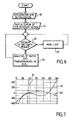
- an initialisation (61) of the interrupt vector providing that, when the instrument vector is activated, it allows the microcontroller to listen to demands and incomings haptic's program instruction, is performed then the program cyclically reads the electro-optic sensor, that has the function to detect the presence of the catheter.
- the program manages to close the electromagnetic clamps (step 62), sending the command of closing to a high tension driver.
- the program reads constantly the value of the encoder, that monitors the rotation of the clamp around its own axis, and the electro-optic sensor, whose value is transformed by the analogical/digital converter of the microcontroller in a digital word : this digital word can be sent by request to the haptic program.
- a main loop (63) to read the encoder value to control the clamper's angular position and to read the A/D converter value that transforms the electro-optic sensor's value in a logic word.
- the program's request is made by sending to the microcontroller the pre-planned sequences of characters that the device is able to interpret.
- the program haptic receiving an answer to the sent command, knows that the microcontroller has received correctly the command and that has performed it.
- step 64 This part of the program is loaded in the microcontroller, that is a Microchip 16f876. If there is no interruption of the haptic program's data request or close of the clamps, then there is a routine analysis (step 64) of the haptic's program's commands and request and values of the sensors are sent on demand transforming the closure clamp command in electrical signal. The interrupt generally by tools insertion involves the routine too.
- a first java interface is loaded and allows to select the type of procedure and to choose one of the available cases.
- the graphical user interface introduces on its part a list of the available devices classified by functionality and associated to a carriage.
- the selection of a device activates the sensors dedicated to this type of device recognition.
- a signal is sent to the haptic interface that activates the locking system related to that carriage and have the device locked to the carriage.
- the position of the device, and therefore of the carriage, is connected to the motor's encoder which provides a value used to manage the movement and the feedback of the carriages. Such value is brought to zero in the phase of the apparatus' initialization and is updated 20 Hz.
- An active cart movement determines a variation of the corresponding encoder value. Such variation is detected by the haptic interface that update the positions of all the following carriages, not yet activated, maintaining the distance between them constant.
- the values of the encoders are sent to the high-level software that manage the devices visualization.
- the system is provided with additional peripheral:
- a mesh structure is used for modelling the body of a patient.
- a mesh is a geometric structure of flat or curve surfaces composed of adjacent polygons.
- Shape and dimension of the polygons are variable, therefore the mesh can easily represent both flat surfaces (a little number of big polygons) and curves surfaces (a big number of little polygons).
- the geometric structure of the mesh is then introduced in the system of physical simulation and can simulates the entire human vascular system.
- the geometric model of the surfaces can be widened with physical property such as the elasticity allowing to simulate the vascular system deformation due to blood pressure, collision with an operating device or expansion produced during the cure of the stenosis, which will authorize a much more realistic simulation.
- an embodiment of the method of simulation used with the invention provides use of algorithms which authorizes correctly the tree-structure of the vascular system and/or the arterial and the venous one together with the mesh technic.
- a spasm is a contraction of an artery with a consequent reduction of the blood flow, which can determine a cardiac frequency variation, high or low, and can change the ECG waveform display.
- a total or partial occlusion of the artery with a device can determine a spasm.
- the simulator of one embodiment of the invention it is possible to simulate a spasm which is obtained by changing the cardiac heartbeat animation frequency, the ECG waveform and the diffusion of the contrast liquid in the vessel.
- Such spasm simulation involves for instance the use of an algorithm as follows :
- the tip of the device can tear one or all of the tissue's layer and pass through them instead of going through the vessel.
- the doctor in this case finds a greater resistance to the advance of the device.
- the dissection is realized showing the device in its position coinciding with the wall of the vase and giving back a tactile feedback adapting continuously to the performing of the dissection.
- Spasm is a suffering state of the patient and must immediately be identified by hemodinamist so that he can proceed to the opportune procedures.
- the spasm is reflected in altered cardiac heartbeat animation frequency, abnormal ECG waveform and less smooth dispersion of the contrast liquid in the vessel
- the model is arranged so that the course of the pressure caused by the hearth can be freely modelled, making possible and easy the simulation of different anatomies, pathological and physiological conditions.
- the model considers the sections of all the veins interested by the blood stream, the veins' elasticity and the eventual presence of stenosis.
- the physical model for the contrast liquid is a fluid-dynamics net model, that means that in every moment length and section of the net are known.
- the simulation algorithm takes into account different parameters i.e. : heart rate, curve of pressure of the cardiac pump (the heart cycle can be appropriately modified), vessel's sections, connections between vessels, length of the vessels, presence of the stenosis and complications.
- Contrast liquid density is calculated in real time along all the vascular system therefore automatically authorizing a time evolution of the contrast liquid simulation.
- the contrast liquid visualization algorithm consists therefore in a perfect mapping in each fraction of the vessel which could be described as follows.
- This algorithm is first based on a contrast fluid library which has the following functionality:
- the API is for instance and here designed to coronography applications and it is structured to allow the following operations:
- the principal components of the simulator are the followings:
- the input signal for the simulation of the hemodynamic's system is a pressure signal, that is obtained through parameterization of the cardiac behavior.
- the hemodynamic flow inside the vascular system is calculated through a simple assembled parameters model, that considers the various branches of the blood vessels like electric nets, whose parameters depend on the geometric characteristics of the considered branches.
- the components that are modelled inside the electric net, equivalent to the vascular system, are the followings:
- the contrast liquid is modelled as a passive scalar inside blood vessels and it is described as mean concentration in every vessel section. It is a function c(x,t) with x varying from 0 to 1, 0 is the value at the tube head.
- ⁇ ,a,D are respectively the entering flow, normal section of the blood vessels and the diffusivity of the passive scalar.
- the integral curve that solve the flow and transport equations is a 4th-order adaptive step Runge-Kutta.
- Figure 8 shows an example of the simulation of the contrast liquid transport inside several simplified model of the vascular tree 68-68'''.
- the mesh consists of triangles. Due to this specific aspect of the method as described and corresponding to an embodiment of the invention, the calculations are more express.
- the visualization algorithm then interrogates the physical simulation algorithm of the fluid in order to obtain information concerning fluid density and the liquid percentage with which the triangles, that belong to the mapping of the net representing the fluid-dynamic system, must be coloured.
- fluid contrast injection is indispensable to the hemodinamists in order to see in the fluoroscopic image the shape of organs crossed by the blood.
- One of the other advantage of this simulation is that it renders the simulation incredibly realistic because it considers the effective point of fluid injection without considering pre-calculated outlines, far from the really operating conditions, and because it considers the effective point of fluid injection and does not show a flat black patch that appears within a given outline
- the model takes into account the presence of blood in the vessels and the interactions between two fluids (blood and contrast liquid).
- the model of the blood pressure takes into account: section, elasticity and presence of stenosis, while it captures and memorises the amount of contrast injected fluid.
- a fluoroscopy's algorithm based on NVIDIA technology.
- This technology generally used to compute special 3D real-time effects rendering for example industrial research and development as in car and vehicle production was not implemented in the present field for practical reason.
- the structure of the algorithm allows to modify every object's pixels colour (more real- simulate x-ray crossing several layers having a better image definition).
- the "floating point blending" develops the realism of the rendering increasing precision from 12-16 bit integer to 16-32 bit floating point.
- the real-time rendering can be offloaded from the CPU to high-performance Graphics Processing Units (GPUs).
- GPUs Graphics Processing Units
- This technology reduces programming complexity using a dedicated high-level language for graphics.
- This method for programming real-time pixel and vertex effects eliminates the need to write applications with extensive low-level assembly code.
- a new graphics programming language can increase the number of applications with cinematic-quality effects.
- the Cg programming language used with the programming of the algorithm involved with the invention provides ease and speed of programming of special effects and accelerates delivery of real-time cinematic-quality graphics experiences.
- Cg runtime feature can benefit from the addition of a new GPU when it becomes available without recompiling or upgrading the software.
- Cg allows for a range of high-fidelity film effects to be efficiently merged into fluoroscopy application and executed in real time such as motion blur and other camera effects and accurate skin, muscles.
- Computerized visual effects involve the manipulation of display data.
- the Cg Language provides the constructs for creating platform-independent shaders.
- the NVIDIA Cg Compiler works with a C-like language for programming shaders on GPUs. This high-level approach offers also several benefits when compared with assembly-level programming such as simplicity, flexibility, reusability, automatic optimisations and low-level access.
- UCA automatically takes advantage of the hardware that is available at the time the shader application is executed.
- NVIDIA Cg Compiler includes optimizations for NVIDIA GPUs making it possible to get the best performance out of the hardware without every shader developer learning the intricacies of every platform.
- Vertex and pixel shaders are used in multi-pass rendering to generate a measure of the object's thickness at each pixel. The thickness at each pixel is then used to produce the colors of the object on screen.
- thickness information is computed each time from the appropriate point of view, and the result is a true volumetric rendering of ordinary polygon objects.
- An efficient method which is further described here after, is used to properly render any closed convex or concave mesh as a thick volume and to handle any intersection cases where opaque objects penetrate the volumes to overcome the effects of aliasing in the per-pixel thickness information.
- Scattering may both add light and attenuate transmitted light.
- the technique for rendering objects as thick volumes start from traditional 3D rendering.
- One advantage of this technique is that the rendering does not change in order to handle various intersection cases and camera positions.
- the depth complexity limit depends on the precision of the thickness information and the number of bits of each color channel used to hold the thickness information. The trade-off between depth complexity and precision can be adjusted from frame to frame. A depth complexity of 16 or 32 volume object faces can be rendered with 15 or 12 bits of depth precision in a single pass.
- the algorithm for computing thickness considers that the polygonal object is rendered to off-screen render targets using some measure of depth interpolated across the polygons, and that the thickness is computed at each rendered pixel.
- the depths of all of an object's front faces at that pixel are summed as well as the depths of all back faces are summed, the thickness through the object being the back face sum minus the front face sum.
- the thickness through the objects is the sum of the depths of all front faces at that pixel subtracted from the sum of the depths of all back faces at that pixel.
- Depth is calculated at each vertex as part of the standard 3D view transform.
- the approach works for any viewpoint in the scene, and it is then easy to animate the volume geometry.
- the technique can be used on the large installed base of Direct3D8 ps.1.3 hardware.
- the fluoroscopy's algorithm being based on NVIDIA technology, there exists an algorithm centralized on the calculation of the thickness of one or more objects, so the overlaps of the objects can be managed working to pixel levels (picture element)
- the structure of the algorithm allows to modify every object's pixels colour (more real- simulate x-ray crossing several layers having a better image definition).
- a fluoroscopy's colouration algorithm to be used with the invention is for instance as follows :
- This algorithm decodes the buffers' values to obtain the fluoroscopy visualization.
- Lines 01 and 02 reads the values stored in the buffers that contain the depth of each pixel of the previous calculated scene's objects.
- line 03 is calculated the thickness of every scene's pixel.
- the thickness has values comprised between 0 and 1. In the overlapping zone the thickness is near 1.
- line 04 the data are decoded : pixels are transformed into the float original format, drawn on the frame buffer and visualised.
- the vascular system and its interaction with the introduced devices are physically simulated through shape, elasticity and resistance, as this model allows the physics modelling and the right interaction of each new device.
- EPD a filter that is delivered in the arteries, against the flow of the blood, in order to stop and to collect fragments that were detached from the stenosis.
- Another example is the stent of newest generation, with an "Y" shape, that is used in the case of Abdominal Aneurysm Aorta.
- the prior-art algorithm allows the expansion of the balloon until it attains the walls of the vase, no ulterior expansion being possible.
- Such algorithm previewed for balloon an expansion with linear course regarding the pressure.
- the algorithm according to the embodiment of the invention more particularly described here authorizes to go further, as it is among other more detailed and takes care of the complexity.
- More particularly physical model with which the balloon is represented consists of n elements independent in their expansion, i.e. provides series of spheres of specific diameters.
- Every sphere's expansion is a linear function of the pressure to which it is expanded until the spheres are not in collision with the walls of the vase (mesh).
- every contact point on the mesh exercises force on the sphere that composes the balloon and every sphere pertaining to the balloon exercises its own force on the mesh.
- the expansion is not linear, but is proportionally limited by the resistance exercised between the mesh and the contact points.
- Every mesh's point can be regulated with its own rigidity (resistance) and such variable resistance of the points pertaining to the mesh allows a full control on the mesh.
- the mesh deformation is on its part based on the pressure exercised from the balloon and at the same time the balloon must continue to expand based on the supplied pressure.
- the balloon's visualization is obtained by interpolation of a curve called "spline" that gives good fluoroscopy results.
- the physical model of the stent consists of a metallic mesh. Every node of the metallic mesh is a particle with own physical properties connected to the other nodes according to an established design. The behaviour of every node can be assimilated to a sphere's behaviour.
- the spheres that represent the stent are compliant with the associated balloon following its behaviour. If the balloon is expanded until the walls of the vase, then also the nodes that compose the mesh of the stent comply to the walls of the vase.
- a self-expandable stent model is close to the standard stent one.
- Every node of the metallic mesh is a particle with its own physical properties and it is connected to the other nodes depending on a pre-established design.
- the spheres that represent the nodes of the mesh are released assuming a speed that depends on their own physical properties and therefore the expansion of the simulated stent according to the invention follows physics of the expansion of a metallic mesh.
- the catheter is modelled with a sequence of cylinders interconnected with a two degrees of rotational freedom's joints.
- systems spring-damper are applied to the bodies in every joint so that for every joint it is possible to define dumping and stiffness.
- a torque is therefore provided for every direction of movement.
- the force that acts on every joint is a function of the torque force that is a function of the angle and the angular velocity.
- the algorithm to model the guide wire is such to concur the local management of viscosity and elasticity.
- the tip of devices is therefore much more ameliorated.
- the hemodinamist perceives this situation as an obviously resistance to the advance of the balloon.
- modelling device as in a preferred embodiment of the invention it has been introduced the possibility to add to the device's physical model the presence of such physical obstacles during the interaction.
- the haptic device gives back to the operator a realistic feedback of the interaction.
- the tactile feedback due to the interaction between two tools contributes to increase the realism of the simulation and to increase the didactic power of the simulator.
- a simulator monitor visualizes therefore the characteristic curves of the patient's electrocardiogram.
- the waveforms are generated from a model that modify them in real time depending on the characteristics of the simulated patient's and depending on the user's actions during the procedure.
- the ECG curves algorithm connects the animation of the heart, the curve of the pump cardiac pressure, pertaining to the physical model of the liquid of contrast, and the model of visualization.
- the visualization is in real time.
- the curves are able to represent also the spasm's effects, particular cardiac situations, tachycardia and lowering of the pressure.
- the ECG is fundamental during angioplasty or angiography procedures because it allows to constantly hold under control the patient's conditions and to correct or suspend the undertaken actions.
- the waveforms are generated from a model that modify them in real time depending on characteristics of the simulated patient during stenting and balloon operations user's actions during the procedure.
- the simulation model of the heart and of the vascular system is responsible for performing the visible movement of the heart, performing the visualized waveforms, regulating the spread of the contrast liquid injected.
- the simulation model of the heart and of the central vascular system communicates the change to the cardiac heartbeat animation and to the ECG, so that the variations are synchronized to advantages of the simulation's realism.
- the simulation model of the heart and of the vascular system is responsible of performing the visible movement of the heart, performing the visualized waveforms, regulating the spread of the contrast liquid injected.
- the simulation model of the heart and of the central vascular system communicates the change to the cardiac heartbeat animation and to the ECG, so that the variations are synchronized to advantage of the simulation's realism.
- a surface model realized with mesh give a simple solution to the anatomies construction based on real patients.
- Tomography data 75 are provided to instruction concerning information extraction (lengths vessels, radius of vessels, morphology) (76) in order to obtain Mesh Construction 77 and Centerline Construction (78).
Landscapes
- Engineering & Computer Science (AREA)
- Physics & Mathematics (AREA)
- General Physics & Mathematics (AREA)
- Health & Medical Sciences (AREA)
- Mathematical Physics (AREA)
- Educational Administration (AREA)
- Medical Informatics (AREA)
- Algebra (AREA)
- Computational Mathematics (AREA)
- General Health & Medical Sciences (AREA)
- Mathematical Analysis (AREA)
- Mathematical Optimization (AREA)
- Chemical & Material Sciences (AREA)
- Pure & Applied Mathematics (AREA)
- Business, Economics & Management (AREA)
- Medicinal Chemistry (AREA)
- Educational Technology (AREA)
- Theoretical Computer Science (AREA)
- Pulmonology (AREA)
- Radiology & Medical Imaging (AREA)
- Surgical Instruments (AREA)
- Accommodation For Nursing Or Treatment Tables (AREA)
- Instructional Devices (AREA)
- Eye Examination Apparatus (AREA)
- Apparatus For Radiation Diagnosis (AREA)
Priority Applications (4)
| Application Number | Priority Date | Filing Date | Title |
|---|---|---|---|
| EP07022742A EP1903537A3 (de) | 2005-07-20 | 2005-07-20 | System und Verfahren zur Simulation eines manuellen Eingriffs in ein medizinisches Verfahren durch einen Benutzer |
| EP05291563.4A EP1746558B1 (de) | 2005-07-20 | 2005-07-20 | System für die Simulation eines manuellen Eingriffes in einem medizinischen Verfahren |
| US11/996,169 US8485829B2 (en) | 2005-07-20 | 2006-07-19 | System and a method for simulating a manual interventional operation by a user in a medical procedure |
| PCT/EP2006/007093 WO2007009763A2 (en) | 2005-07-20 | 2006-07-19 | A system and a method for simulating a manual interventional operation by a user in a medical procedure |
Applications Claiming Priority (1)
| Application Number | Priority Date | Filing Date | Title |
|---|---|---|---|
| EP05291563.4A EP1746558B1 (de) | 2005-07-20 | 2005-07-20 | System für die Simulation eines manuellen Eingriffes in einem medizinischen Verfahren |
Related Child Applications (2)
| Application Number | Title | Priority Date | Filing Date |
|---|---|---|---|
| EP07022742A Division EP1903537A3 (de) | 2005-07-20 | 2005-07-20 | System und Verfahren zur Simulation eines manuellen Eingriffs in ein medizinisches Verfahren durch einen Benutzer |
| EP07022742.6 Division-Into | 2007-11-23 |
Publications (3)
| Publication Number | Publication Date |
|---|---|
| EP1746558A2 true EP1746558A2 (de) | 2007-01-24 |
| EP1746558A3 EP1746558A3 (de) | 2007-05-02 |
| EP1746558B1 EP1746558B1 (de) | 2013-07-17 |
Family
ID=35058906
Family Applications (2)
| Application Number | Title | Priority Date | Filing Date |
|---|---|---|---|
| EP07022742A Withdrawn EP1903537A3 (de) | 2005-07-20 | 2005-07-20 | System und Verfahren zur Simulation eines manuellen Eingriffs in ein medizinisches Verfahren durch einen Benutzer |
| EP05291563.4A Expired - Lifetime EP1746558B1 (de) | 2005-07-20 | 2005-07-20 | System für die Simulation eines manuellen Eingriffes in einem medizinischen Verfahren |
Family Applications Before (1)
| Application Number | Title | Priority Date | Filing Date |
|---|---|---|---|
| EP07022742A Withdrawn EP1903537A3 (de) | 2005-07-20 | 2005-07-20 | System und Verfahren zur Simulation eines manuellen Eingriffs in ein medizinisches Verfahren durch einen Benutzer |
Country Status (3)
| Country | Link |
|---|---|
| US (1) | US8485829B2 (de) |
| EP (2) | EP1903537A3 (de) |
| WO (1) | WO2007009763A2 (de) |
Cited By (7)
| Publication number | Priority date | Publication date | Assignee | Title |
|---|---|---|---|---|
| WO2009132067A1 (en) * | 2008-04-22 | 2009-10-29 | Immersion Medical | Systems and methods for surgical simulation and training |
| US8521556B2 (en) | 2007-12-18 | 2013-08-27 | Koninklijke Philips N.V. | Integration of physiological models in medical decision support systems |
| CN103354050A (zh) * | 2013-08-01 | 2013-10-16 | 陈廷 | 多状态运动研究装置 |
| CN104361793B (zh) * | 2013-08-01 | 2016-08-31 | 许昌学院 | 多状态运动研究装置 |
| CN106057041A (zh) * | 2016-06-15 | 2016-10-26 | 蒲元昊 | 一种解决电磁感应问题的实验仪器及操作方法 |
| CN108828924A (zh) * | 2018-05-18 | 2018-11-16 | 浙江建林电子电气股份有限公司 | 全息摄影成像平台 |
| FR3109237A1 (fr) | 2020-04-10 | 2021-10-15 | Virtualisurg | Système de connexion d’un dispositif d’entraînement chirurgical à un dispositif virtuel |
Families Citing this family (24)
| Publication number | Priority date | Publication date | Assignee | Title |
|---|---|---|---|---|
| MX2009004291A (es) * | 2006-10-22 | 2009-09-07 | Idev Technologies Inc | Metodos para asegurar extremos de hebra y los dispositivos resultantes. |
| US9978288B2 (en) | 2009-02-13 | 2018-05-22 | University Of Florida Research Foundation, Inc. | Communication and skills training using interactive virtual humans |
| US9754512B2 (en) * | 2009-09-30 | 2017-09-05 | University Of Florida Research Foundation, Inc. | Real-time feedback of task performance |
| DE102009048994A1 (de) * | 2009-10-09 | 2011-04-14 | Karl Storz Gmbh & Co. Kg | Simulationssystem für das Training endoskopischer Operationen |
| RU2474883C1 (ru) * | 2011-05-26 | 2013-02-10 | Учреждение Российской академии наук Институт проблем управления им. В.А. Трапезникова РАН | Тренажер для освоения интервенционных методов диагностики и лечения заболеваний сосудов сердца |
| US8965084B2 (en) * | 2012-01-19 | 2015-02-24 | Siemens Aktiengesellschaft | Blood flow computation in vessels with implanted devices |
| US20130237796A1 (en) * | 2012-03-07 | 2013-09-12 | Poincare Systems, Inc. | Supports for components in catheters |
| US9390232B2 (en) * | 2014-03-24 | 2016-07-12 | Heartflow, Inc. | Systems and methods for modeling changes in patient-specific blood vessel geometry and boundary conditions |
| US9449145B2 (en) * | 2014-04-22 | 2016-09-20 | Heartflow, Inc. | Systems and methods for virtual contrast agent simulation and computational fluid dynamics (CFD) to compute functional significance of stenoses |
| CA2921848C (en) * | 2016-02-26 | 2017-07-18 | Cae Healthcare Canada Inc. | Apparatus for simulating insertion of an elongated instrument into a structure and medical insertion simulator |
| CA2921855C (en) * | 2016-02-26 | 2017-05-02 | Cae Healthcare Canada Inc. | Apparatus for simulating insertion of an elongated instrument into a structure and medical insertion simulator |
| US9754513B1 (en) * | 2016-02-26 | 2017-09-05 | Cae Healthcare Canada Inc. | Apparatus for simulating insertion of an elongated instrument into a structure including a pulley and a pulley position sensing arrangement |
| WO2018118858A1 (en) | 2016-12-19 | 2018-06-28 | National Board Of Medical Examiners | Medical training and performance assessment instruments, methods, and systems |
| US11501661B2 (en) * | 2018-03-29 | 2022-11-15 | Cae Healthcare Canada Inc. | Method and system for simulating an insertion of an elongated instrument into a subject |
| US11968414B1 (en) | 2018-06-18 | 2024-04-23 | Sintec Media Ltd. | Systems and methods for forecasting program viewership |
| GB2582006A (en) * | 2019-03-08 | 2020-09-09 | Jaguar Land Rover Ltd | Vehicle controller |
| WO2021092414A1 (en) * | 2019-11-07 | 2021-05-14 | Level Ex Inc. | Methods and systems for rendering images |
| US12096986B2 (en) | 2019-12-05 | 2024-09-24 | The Board Of Regents Of The University Of Nebraska | Computational simulation platform for planning of interventional procedures |
| US11026749B1 (en) | 2019-12-05 | 2021-06-08 | Board Of Regents Of The University Of Nebraska | Computational simulation platform for planning of interventional procedures |
| FR3109078B1 (fr) | 2020-04-10 | 2022-05-06 | Virtualisurg | Dispositif de simulation chirurgicale |
| CN112382176A (zh) * | 2020-10-21 | 2021-02-19 | 北京科技大学 | 一种磁悬浮驱动装置及方法 |
| CN112991444B (zh) * | 2021-02-10 | 2023-06-20 | 北京字跳网络技术有限公司 | 位置确定方法及设备 |
| CN114391950B (zh) * | 2021-12-15 | 2024-02-27 | 深圳爱博合创医疗机器人有限公司 | 一种具有防撞功能的介入手术机器人 |
| CN114241875A (zh) * | 2022-01-19 | 2022-03-25 | 哈尔滨医科大学 | 一种腔内心电定位picc置管技术模拟训练系统 |
Citations (2)
| Publication number | Priority date | Publication date | Assignee | Title |
|---|---|---|---|---|
| US4907973A (en) | 1988-11-14 | 1990-03-13 | Hon David C | Expert system simulator for modeling realistic internal environments and performance |
| US5821920A (en) | 1994-07-14 | 1998-10-13 | Immersion Human Interface Corporation | Control input device for interfacing an elongated flexible object with a computer system |
Family Cites Families (28)
| Publication number | Priority date | Publication date | Assignee | Title |
|---|---|---|---|---|
| US4209852A (en) * | 1974-11-11 | 1980-06-24 | Hyatt Gilbert P | Signal processing and memory arrangement |
| US7192284B2 (en) * | 2000-08-17 | 2007-03-20 | Gaumard Scientific Company, Inc. | Interactive education system for teaching patient care |
| US5800179A (en) * | 1996-07-23 | 1998-09-01 | Medical Simulation Corporation | System for training persons to perform minimally invasive surgical procedures |
| US6037948A (en) * | 1997-03-07 | 2000-03-14 | Silicon Graphics, Inc. | Method, system, and computer program product for updating texture with overscan |
| US7191110B1 (en) * | 1998-02-03 | 2007-03-13 | University Of Illinois, Board Of Trustees | Patient specific circulation model |
| US6217525B1 (en) * | 1998-04-30 | 2001-04-17 | Medtronic Physio-Control Manufacturing Corp. | Reduced lead set device and method for detecting acute cardiac ischemic conditions |
| JP2000047568A (ja) * | 1998-07-10 | 2000-02-18 | Mitsubishi Electric Inf Technol Center America Inc | 同心状の器具の位置を感知するセンサ―装置、同心状の器具の位置を感知・制御する装置、複数の同心状の器具の移動と回転の位置の指示を発生する方法および一組の伸長した同心状の管状物体を作動するアクチュエ―タアッセンブリ |
| US6452596B1 (en) * | 1998-10-06 | 2002-09-17 | International Business Machines Corporation | Methods and apparatus for the efficient compression of non-manifold polygonal meshes |
| US6249287B1 (en) * | 1998-11-16 | 2001-06-19 | General Electric Company | Method of modeling a closed surface geometry |
| US6538634B1 (en) * | 1998-12-18 | 2003-03-25 | Kent Ridge Digital Labs | Apparatus for the simulation of image-guided surgery |
| US6756978B1 (en) * | 1999-04-19 | 2004-06-29 | Microsoft Corporation | Apparatus and method for sharing antialiasing memory across multiple displays |
| US7261565B2 (en) * | 2000-05-19 | 2007-08-28 | Simbionix Ltd. | Endoscopic tutorial system for the pancreatic system |
| WO2002070980A1 (en) * | 2001-03-06 | 2002-09-12 | The Johns Hopkins University School Of Medicine | Simulation system for image-guided medical procedures |
| US20050018885A1 (en) * | 2001-05-31 | 2005-01-27 | Xuesong Chen | System and method of anatomical modeling |
| US7056123B2 (en) * | 2001-07-16 | 2006-06-06 | Immersion Corporation | Interface apparatus with cable-driven force feedback and grounded actuators |
| US7363198B2 (en) * | 2001-10-29 | 2008-04-22 | The Board Of Trustees Of The Leland Stanford Junior University | Long elements method for simulation of deformable objects |
| WO2004026178A2 (en) * | 2002-09-19 | 2004-04-01 | Exstent Limited | External stent |
| US7998107B2 (en) * | 2002-09-24 | 2011-08-16 | Kensey Nash Corporation | Interventional procedure drive and control system |
| US7113623B2 (en) * | 2002-10-08 | 2006-09-26 | The Regents Of The University Of Colorado | Methods and systems for display and analysis of moving arterial tree structures |
| EP1576565B1 (de) * | 2002-12-03 | 2018-07-11 | Mentice AB | Interventionelle simulatorvorrichtung |
| SE0203567D0 (sv) * | 2002-12-03 | 2002-12-03 | Mentice Ab | An interventional simulator control system |
| US20050010326A1 (en) * | 2003-05-28 | 2005-01-13 | Vincent Hayward | Method and apparatus for synthesizing virtual interaction between rigid and deformable bodies |
| US20040249617A1 (en) * | 2003-06-03 | 2004-12-09 | Pccw-Hkt Datacom Services Limited | Selective, pregressive transmission of 3D geometry models with the pre-ordered hierarchical meshes |
| EP1677273A4 (de) * | 2003-10-16 | 2013-12-04 | Nagoya Ind Science Res Inst | Dreidimensionales modell |
| US7333643B2 (en) * | 2004-01-30 | 2008-02-19 | Chase Medical, L.P. | System and method for facilitating cardiac intervention |
| US7455523B2 (en) * | 2004-06-14 | 2008-11-25 | Medical Simulation Corporation | Medical simulation system and method |
| WO2006062958A2 (en) * | 2004-12-10 | 2006-06-15 | Worcester Polytechnic Institute | Image-based computational mechanical analysis and indexing for cardiovascular diseases |
| EP1746559A1 (de) | 2005-07-20 | 2007-01-24 | Richstone Consulting LLC | Verfahren für die Simulation eines manuellen Eingriffes in einem midizinischen Verfahren. |
-
2005
- 2005-07-20 EP EP07022742A patent/EP1903537A3/de not_active Withdrawn
- 2005-07-20 EP EP05291563.4A patent/EP1746558B1/de not_active Expired - Lifetime
-
2006
- 2006-07-19 WO PCT/EP2006/007093 patent/WO2007009763A2/en not_active Ceased
- 2006-07-19 US US11/996,169 patent/US8485829B2/en not_active Expired - Fee Related
Patent Citations (2)
| Publication number | Priority date | Publication date | Assignee | Title |
|---|---|---|---|---|
| US4907973A (en) | 1988-11-14 | 1990-03-13 | Hon David C | Expert system simulator for modeling realistic internal environments and performance |
| US5821920A (en) | 1994-07-14 | 1998-10-13 | Immersion Human Interface Corporation | Control input device for interfacing an elongated flexible object with a computer system |
Cited By (8)
| Publication number | Priority date | Publication date | Assignee | Title |
|---|---|---|---|---|
| US8521556B2 (en) | 2007-12-18 | 2013-08-27 | Koninklijke Philips N.V. | Integration of physiological models in medical decision support systems |
| WO2009132067A1 (en) * | 2008-04-22 | 2009-10-29 | Immersion Medical | Systems and methods for surgical simulation and training |
| CN103354050A (zh) * | 2013-08-01 | 2013-10-16 | 陈廷 | 多状态运动研究装置 |
| CN104361793B (zh) * | 2013-08-01 | 2016-08-31 | 许昌学院 | 多状态运动研究装置 |
| CN106057041A (zh) * | 2016-06-15 | 2016-10-26 | 蒲元昊 | 一种解决电磁感应问题的实验仪器及操作方法 |
| CN108828924A (zh) * | 2018-05-18 | 2018-11-16 | 浙江建林电子电气股份有限公司 | 全息摄影成像平台 |
| CN108828924B (zh) * | 2018-05-18 | 2020-10-30 | 浙江建林电子电气股份有限公司 | 全息摄影成像平台 |
| FR3109237A1 (fr) | 2020-04-10 | 2021-10-15 | Virtualisurg | Système de connexion d’un dispositif d’entraînement chirurgical à un dispositif virtuel |
Also Published As
| Publication number | Publication date |
|---|---|
| EP1746558A3 (de) | 2007-05-02 |
| WO2007009763A3 (en) | 2007-05-18 |
| EP1903537A2 (de) | 2008-03-26 |
| WO2007009763A2 (en) | 2007-01-25 |
| EP1903537A3 (de) | 2008-06-11 |
| EP1746558B1 (de) | 2013-07-17 |
| US8485829B2 (en) | 2013-07-16 |
| US20080286735A1 (en) | 2008-11-20 |
Similar Documents
| Publication | Publication Date | Title |
|---|---|---|
| EP1746558B1 (de) | System für die Simulation eines manuellen Eingriffes in einem medizinischen Verfahren | |
| Dawson et al. | Designing a computer‐based simulator for interventional cardiology training | |
| US7261565B2 (en) | Endoscopic tutorial system for the pancreatic system | |
| Cotin et al. | ICTS, an interventional cardiology training system | |
| Ullrich et al. | Haptic palpation for medical simulation in virtual environments | |
| US8639485B2 (en) | Systems and methods for editing a model of a physical system for a simulation | |
| Tuggy | Virtual reality flexible sigmoidoscopy simulator training: impact on resident performance | |
| US20080020362A1 (en) | Methods and Apparatus for Simulaton of Endovascular and Endoluminal Procedures | |
| US4907973A (en) | Expert system simulator for modeling realistic internal environments and performance | |
| Korzeniowski et al. | VCSim3: a VR simulator for cardiovascular interventions | |
| KR101083808B1 (ko) | 형광투시조영술의 시뮬레이션을 위한 가상 형광투시영상의 실시간 렌더링방법 | |
| Burdea et al. | Virtual reality training for the diagnosis of prostate cancer | |
| US8491307B2 (en) | Interventional simulator control system | |
| CN104574503B (zh) | 造影剂扩散过程模拟装置 | |
| JP5144669B2 (ja) | 可撓性物体の模擬システム | |
| EP1746559A1 (de) | Verfahren für die Simulation eines manuellen Eingriffes in einem midizinischen Verfahren. | |
| Pan et al. | Graphic and haptic simulation system for virtual laparoscopic rectum surgery | |
| Zhou et al. | Cardiovascular‐interventional‐surgery virtual training platform and its preliminary evaluation | |
| Wu et al. | A preliminary real‐time and realistic simulation environment for percutaneous coronary intervention | |
| Radetzky et al. | Elastodynamic shape modeler: A tool for defining the deformation behavior of virtual tissues | |
| Luboz et al. | Real-time Seldinger technique simulation in complex vascular models | |
| Li et al. | Haptics-equiped interactive PCI simulation for patient-specific surgery training and rehearsing | |
| Anderson et al. | A vascular catheterization simulator for training and treatment planning | |
| US7375726B2 (en) | Method and system for simulation of a thread in computer graphics simulations | |
| EP1576564B1 (de) | Interventionelle simulatorsteuerung |
Legal Events
| Date | Code | Title | Description |
|---|---|---|---|
| PUAI | Public reference made under article 153(3) epc to a published international application that has entered the european phase |
Free format text: ORIGINAL CODE: 0009012 |
|
| AK | Designated contracting states |
Kind code of ref document: A2 Designated state(s): AT BE BG CH CY CZ DE DK EE ES FI FR GB GR HU IE IS IT LI LT LU LV MC NL PL PT RO SE SI SK TR |
|
| AX | Request for extension of the european patent |
Extension state: AL BA HR MK YU |
|
| PUAL | Search report despatched |
Free format text: ORIGINAL CODE: 0009013 |
|
| AK | Designated contracting states |
Kind code of ref document: A3 Designated state(s): AT BE BG CH CY CZ DE DK EE ES FI FR GB GR HU IE IS IT LI LT LU LV MC NL PL PT RO SE SI SK TR |
|
| AX | Request for extension of the european patent |
Extension state: AL BA HR MK YU |
|
| 17P | Request for examination filed |
Effective date: 20071016 |
|
| AKX | Designation fees paid |
Designated state(s): AT BE BG CH CY CZ DE DK EE ES FI FR GB GR HU IE IS IT LI LT LU LV MC NL PL PT RO SE SI SK TR |
|
| AXX | Extension fees paid |
Extension state: AL Payment date: 20071016 Extension state: HR Payment date: 20071016 Extension state: MK Payment date: 20071016 Extension state: YU Payment date: 20071016 Extension state: BA Payment date: 20071016 |
|
| REG | Reference to a national code |
Ref country code: DE Ref legal event code: R079 Ref document number: 602005040411 Country of ref document: DE Free format text: PREVIOUS MAIN CLASS: G09B0023280000 Ipc: G09B0023300000 |
|
| RIC1 | Information provided on ipc code assigned before grant |
Ipc: G09B 23/28 20060101ALI20121121BHEP Ipc: G09B 23/30 20060101AFI20121121BHEP |
|
| GRAP | Despatch of communication of intention to grant a patent |
Free format text: ORIGINAL CODE: EPIDOSNIGR1 |
|
| GRAS | Grant fee paid |
Free format text: ORIGINAL CODE: EPIDOSNIGR3 |
|
| GRAL | Information related to payment of fee for publishing/printing deleted |
Free format text: ORIGINAL CODE: EPIDOSDIGR3 |
|
| GRAS | Grant fee paid |
Free format text: ORIGINAL CODE: EPIDOSNIGR3 |
|
| GRAA | (expected) grant |
Free format text: ORIGINAL CODE: 0009210 |
|
| RAP1 | Party data changed (applicant data changed or rights of an application transferred) |
Owner name: MEDTAG LTD. |
|
| AK | Designated contracting states |
Kind code of ref document: B1 Designated state(s): AT BE BG CH CY CZ DE DK EE ES FI FR GB GR HU IE IS IT LI LT LU LV MC NL PL PT RO SE SI SK TR |
|
| AX | Request for extension of the european patent |
Extension state: AL BA HR MK YU |
|
| REG | Reference to a national code |
Ref country code: GB Ref legal event code: FG4D |
|
| REG | Reference to a national code |
Ref country code: CH Ref legal event code: EP |
|
| REG | Reference to a national code |
Ref country code: IE Ref legal event code: FG4D |
|
| REG | Reference to a national code |
Ref country code: AT Ref legal event code: REF Ref document number: 622630 Country of ref document: AT Kind code of ref document: T Effective date: 20130815 |
|
| REG | Reference to a national code |
Ref country code: DE Ref legal event code: R096 Ref document number: 602005040411 Country of ref document: DE Effective date: 20130912 |
|
| REG | Reference to a national code |
Ref country code: AT Ref legal event code: MK05 Ref document number: 622630 Country of ref document: AT Kind code of ref document: T Effective date: 20130717 |
|
| REG | Reference to a national code |
Ref country code: NL Ref legal event code: VDEP Effective date: 20130717 |
|
| REG | Reference to a national code |
Ref country code: LT Ref legal event code: MG4D |
|
| PG25 | Lapsed in a contracting state [announced via postgrant information from national office to epo] |
Ref country code: IS Free format text: LAPSE BECAUSE OF FAILURE TO SUBMIT A TRANSLATION OF THE DESCRIPTION OR TO PAY THE FEE WITHIN THE PRESCRIBED TIME-LIMIT Effective date: 20131117 Ref country code: CY Free format text: LAPSE BECAUSE OF FAILURE TO SUBMIT A TRANSLATION OF THE DESCRIPTION OR TO PAY THE FEE WITHIN THE PRESCRIBED TIME-LIMIT Effective date: 20130717 Ref country code: LT Free format text: LAPSE BECAUSE OF FAILURE TO SUBMIT A TRANSLATION OF THE DESCRIPTION OR TO PAY THE FEE WITHIN THE PRESCRIBED TIME-LIMIT Effective date: 20130717 Ref country code: PT Free format text: LAPSE BECAUSE OF FAILURE TO SUBMIT A TRANSLATION OF THE DESCRIPTION OR TO PAY THE FEE WITHIN THE PRESCRIBED TIME-LIMIT Effective date: 20131118 Ref country code: AT Free format text: LAPSE BECAUSE OF FAILURE TO SUBMIT A TRANSLATION OF THE DESCRIPTION OR TO PAY THE FEE WITHIN THE PRESCRIBED TIME-LIMIT Effective date: 20130717 Ref country code: BE Free format text: LAPSE BECAUSE OF FAILURE TO SUBMIT A TRANSLATION OF THE DESCRIPTION OR TO PAY THE FEE WITHIN THE PRESCRIBED TIME-LIMIT Effective date: 20130717 Ref country code: SE Free format text: LAPSE BECAUSE OF FAILURE TO SUBMIT A TRANSLATION OF THE DESCRIPTION OR TO PAY THE FEE WITHIN THE PRESCRIBED TIME-LIMIT Effective date: 20130717 |
|
| PG25 | Lapsed in a contracting state [announced via postgrant information from national office to epo] |
Ref country code: FI Free format text: LAPSE BECAUSE OF FAILURE TO SUBMIT A TRANSLATION OF THE DESCRIPTION OR TO PAY THE FEE WITHIN THE PRESCRIBED TIME-LIMIT Effective date: 20130717 Ref country code: ES Free format text: LAPSE BECAUSE OF FAILURE TO SUBMIT A TRANSLATION OF THE DESCRIPTION OR TO PAY THE FEE WITHIN THE PRESCRIBED TIME-LIMIT Effective date: 20131028 Ref country code: PL Free format text: LAPSE BECAUSE OF FAILURE TO SUBMIT A TRANSLATION OF THE DESCRIPTION OR TO PAY THE FEE WITHIN THE PRESCRIBED TIME-LIMIT Effective date: 20130717 Ref country code: NL Free format text: LAPSE BECAUSE OF FAILURE TO SUBMIT A TRANSLATION OF THE DESCRIPTION OR TO PAY THE FEE WITHIN THE PRESCRIBED TIME-LIMIT Effective date: 20130717 Ref country code: LV Free format text: LAPSE BECAUSE OF FAILURE TO SUBMIT A TRANSLATION OF THE DESCRIPTION OR TO PAY THE FEE WITHIN THE PRESCRIBED TIME-LIMIT Effective date: 20130717 Ref country code: SI Free format text: LAPSE BECAUSE OF FAILURE TO SUBMIT A TRANSLATION OF THE DESCRIPTION OR TO PAY THE FEE WITHIN THE PRESCRIBED TIME-LIMIT Effective date: 20130717 |
|
| REG | Reference to a national code |
Ref country code: CH Ref legal event code: PL |
|
| REG | Reference to a national code |
Ref country code: IE Ref legal event code: MM4A |
|
| PG25 | Lapsed in a contracting state [announced via postgrant information from national office to epo] |
Ref country code: LI Free format text: LAPSE BECAUSE OF NON-PAYMENT OF DUE FEES Effective date: 20130731 Ref country code: DE Free format text: LAPSE BECAUSE OF NON-PAYMENT OF DUE FEES Effective date: 20140201 Ref country code: EE Free format text: LAPSE BECAUSE OF FAILURE TO SUBMIT A TRANSLATION OF THE DESCRIPTION OR TO PAY THE FEE WITHIN THE PRESCRIBED TIME-LIMIT Effective date: 20130717 Ref country code: SK Free format text: LAPSE BECAUSE OF FAILURE TO SUBMIT A TRANSLATION OF THE DESCRIPTION OR TO PAY THE FEE WITHIN THE PRESCRIBED TIME-LIMIT Effective date: 20130717 Ref country code: CH Free format text: LAPSE BECAUSE OF NON-PAYMENT OF DUE FEES Effective date: 20130731 Ref country code: CZ Free format text: LAPSE BECAUSE OF FAILURE TO SUBMIT A TRANSLATION OF THE DESCRIPTION OR TO PAY THE FEE WITHIN THE PRESCRIBED TIME-LIMIT Effective date: 20130717 Ref country code: MC Free format text: LAPSE BECAUSE OF FAILURE TO SUBMIT A TRANSLATION OF THE DESCRIPTION OR TO PAY THE FEE WITHIN THE PRESCRIBED TIME-LIMIT Effective date: 20130717 Ref country code: DK Free format text: LAPSE BECAUSE OF FAILURE TO SUBMIT A TRANSLATION OF THE DESCRIPTION OR TO PAY THE FEE WITHIN THE PRESCRIBED TIME-LIMIT Effective date: 20130717 Ref country code: RO Free format text: LAPSE BECAUSE OF FAILURE TO SUBMIT A TRANSLATION OF THE DESCRIPTION OR TO PAY THE FEE WITHIN THE PRESCRIBED TIME-LIMIT Effective date: 20130717 |
|
| REG | Reference to a national code |
Ref country code: DE Ref legal event code: R119 Ref document number: 602005040411 Country of ref document: DE Effective date: 20140201 |
|
| PLBE | No opposition filed within time limit |
Free format text: ORIGINAL CODE: 0009261 |
|
| STAA | Information on the status of an ep patent application or granted ep patent |
Free format text: STATUS: NO OPPOSITION FILED WITHIN TIME LIMIT |
|
| PG25 | Lapsed in a contracting state [announced via postgrant information from national office to epo] |
Ref country code: IT Free format text: LAPSE BECAUSE OF FAILURE TO SUBMIT A TRANSLATION OF THE DESCRIPTION OR TO PAY THE FEE WITHIN THE PRESCRIBED TIME-LIMIT Effective date: 20130717 |
|
| REG | Reference to a national code |
Ref country code: FR Ref legal event code: ST Effective date: 20140505 |
|
| 26N | No opposition filed |
Effective date: 20140422 |
|
| PG25 | Lapsed in a contracting state [announced via postgrant information from national office to epo] |
Ref country code: IE Free format text: LAPSE BECAUSE OF NON-PAYMENT OF DUE FEES Effective date: 20130720 |
|
| PG25 | Lapsed in a contracting state [announced via postgrant information from national office to epo] |
Ref country code: FR Free format text: LAPSE BECAUSE OF NON-PAYMENT OF DUE FEES Effective date: 20130917 |
|
| PG25 | Lapsed in a contracting state [announced via postgrant information from national office to epo] |
Ref country code: TR Free format text: LAPSE BECAUSE OF FAILURE TO SUBMIT A TRANSLATION OF THE DESCRIPTION OR TO PAY THE FEE WITHIN THE PRESCRIBED TIME-LIMIT Effective date: 20130717 |
|
| PG25 | Lapsed in a contracting state [announced via postgrant information from national office to epo] |
Ref country code: HU Free format text: LAPSE BECAUSE OF FAILURE TO SUBMIT A TRANSLATION OF THE DESCRIPTION OR TO PAY THE FEE WITHIN THE PRESCRIBED TIME-LIMIT; INVALID AB INITIO Effective date: 20050720 Ref country code: LU Free format text: LAPSE BECAUSE OF NON-PAYMENT OF DUE FEES Effective date: 20130720 Ref country code: BG Free format text: LAPSE BECAUSE OF FAILURE TO SUBMIT A TRANSLATION OF THE DESCRIPTION OR TO PAY THE FEE WITHIN THE PRESCRIBED TIME-LIMIT Effective date: 20130717 |
|
| PG25 | Lapsed in a contracting state [announced via postgrant information from national office to epo] |
Ref country code: GR Free format text: LAPSE BECAUSE OF NON-PAYMENT OF DUE FEES Effective date: 20130717 |
|
| PGFP | Annual fee paid to national office [announced via postgrant information from national office to epo] |
Ref country code: GB Payment date: 20170719 Year of fee payment: 13 |
|
| GBPC | Gb: european patent ceased through non-payment of renewal fee |
Effective date: 20180720 |
|
| PG25 | Lapsed in a contracting state [announced via postgrant information from national office to epo] |
Ref country code: GB Free format text: LAPSE BECAUSE OF NON-PAYMENT OF DUE FEES Effective date: 20180720 |