EP1746597A2 - Méthode et appareil d'enregistrement de formats différents sur un disque optique multicouches - Google Patents
Méthode et appareil d'enregistrement de formats différents sur un disque optique multicouches Download PDFInfo
- Publication number
- EP1746597A2 EP1746597A2 EP06117379A EP06117379A EP1746597A2 EP 1746597 A2 EP1746597 A2 EP 1746597A2 EP 06117379 A EP06117379 A EP 06117379A EP 06117379 A EP06117379 A EP 06117379A EP 1746597 A2 EP1746597 A2 EP 1746597A2
- Authority
- EP
- European Patent Office
- Prior art keywords
- information
- format
- information recording
- disc
- layer
- Prior art date
- Legal status (The legal status is an assumption and is not a legal conclusion. Google has not performed a legal analysis and makes no representation as to the accuracy of the status listed.)
- Withdrawn
Links
- 230000003287 optical effect Effects 0.000 title claims description 222
- 238000000034 method Methods 0.000 title claims description 39
- 238000007726 management method Methods 0.000 claims description 22
- 239000010410 layer Substances 0.000 description 256
- 230000006870 function Effects 0.000 description 46
- 230000004044 response Effects 0.000 description 25
- 238000012545 processing Methods 0.000 description 21
- 239000002355 dual-layer Substances 0.000 description 14
- 230000007704 transition Effects 0.000 description 10
- 239000000758 substrate Substances 0.000 description 7
- 230000005540 biological transmission Effects 0.000 description 5
- 239000002356 single layer Substances 0.000 description 5
- 230000008859 change Effects 0.000 description 2
- 238000006243 chemical reaction Methods 0.000 description 2
- 238000004891 communication Methods 0.000 description 2
- 238000010586 diagram Methods 0.000 description 2
- 230000000694 effects Effects 0.000 description 2
- 230000001678 irradiating effect Effects 0.000 description 2
- 238000012546 transfer Methods 0.000 description 2
- 102100030840 AT-rich interactive domain-containing protein 4B Human genes 0.000 description 1
- 101000792935 Homo sapiens AT-rich interactive domain-containing protein 4B Proteins 0.000 description 1
- 238000007476 Maximum Likelihood Methods 0.000 description 1
- 230000002411 adverse Effects 0.000 description 1
- 230000004075 alteration Effects 0.000 description 1
- 230000001427 coherent effect Effects 0.000 description 1
- 238000012937 correction Methods 0.000 description 1
- 238000001514 detection method Methods 0.000 description 1
- 239000000463 material Substances 0.000 description 1
- 230000000737 periodic effect Effects 0.000 description 1
- 239000011295 pitch Substances 0.000 description 1
- 230000008569 process Effects 0.000 description 1
Images








Classifications
-
- G—PHYSICS
- G11—INFORMATION STORAGE
- G11B—INFORMATION STORAGE BASED ON RELATIVE MOVEMENT BETWEEN RECORD CARRIER AND TRANSDUCER
- G11B7/00—Recording or reproducing by optical means, e.g. recording using a thermal beam of optical radiation by modifying optical properties or the physical structure, reproducing using an optical beam at lower power by sensing optical properties; Record carriers therefor
- G11B7/007—Arrangement of the information on the record carrier, e.g. form of tracks, actual track shape, e.g. wobbled, or cross-section, e.g. v-shaped; Sequential information structures, e.g. sectoring or header formats within a track
- G11B7/00736—Auxiliary data, e.g. lead-in, lead-out, Power Calibration Area [PCA], Burst Cutting Area [BCA], control information
-
- G—PHYSICS
- G11—INFORMATION STORAGE
- G11B—INFORMATION STORAGE BASED ON RELATIVE MOVEMENT BETWEEN RECORD CARRIER AND TRANSDUCER
- G11B7/00—Recording or reproducing by optical means, e.g. recording using a thermal beam of optical radiation by modifying optical properties or the physical structure, reproducing using an optical beam at lower power by sensing optical properties; Record carriers therefor
- G11B7/007—Arrangement of the information on the record carrier, e.g. form of tracks, actual track shape, e.g. wobbled, or cross-section, e.g. v-shaped; Sequential information structures, e.g. sectoring or header formats within a track
-
- G—PHYSICS
- G11—INFORMATION STORAGE
- G11B—INFORMATION STORAGE BASED ON RELATIVE MOVEMENT BETWEEN RECORD CARRIER AND TRANSDUCER
- G11B20/00—Signal processing not specific to the method of recording or reproducing; Circuits therefor
- G11B20/10—Digital recording or reproducing
- G11B20/12—Formatting, e.g. arrangement of data block or words on the record carriers
-
- G—PHYSICS
- G11—INFORMATION STORAGE
- G11B—INFORMATION STORAGE BASED ON RELATIVE MOVEMENT BETWEEN RECORD CARRIER AND TRANSDUCER
- G11B20/00—Signal processing not specific to the method of recording or reproducing; Circuits therefor
- G11B20/10—Digital recording or reproducing
- G11B20/12—Formatting, e.g. arrangement of data block or words on the record carriers
- G11B20/1217—Formatting, e.g. arrangement of data block or words on the record carriers on discs
-
- G—PHYSICS
- G11—INFORMATION STORAGE
- G11B—INFORMATION STORAGE BASED ON RELATIVE MOVEMENT BETWEEN RECORD CARRIER AND TRANSDUCER
- G11B20/00—Signal processing not specific to the method of recording or reproducing; Circuits therefor
- G11B20/10—Digital recording or reproducing
- G11B20/12—Formatting, e.g. arrangement of data block or words on the record carriers
- G11B20/1262—Formatting, e.g. arrangement of data block or words on the record carriers with more than one format/standard, e.g. conversion from CD-audio format to R-DAT format
-
- G—PHYSICS
- G11—INFORMATION STORAGE
- G11B—INFORMATION STORAGE BASED ON RELATIVE MOVEMENT BETWEEN RECORD CARRIER AND TRANSDUCER
- G11B7/00—Recording or reproducing by optical means, e.g. recording using a thermal beam of optical radiation by modifying optical properties or the physical structure, reproducing using an optical beam at lower power by sensing optical properties; Record carriers therefor
- G11B7/004—Recording, reproducing or erasing methods; Read, write or erase circuits therefor
-
- G—PHYSICS
- G11—INFORMATION STORAGE
- G11B—INFORMATION STORAGE BASED ON RELATIVE MOVEMENT BETWEEN RECORD CARRIER AND TRANSDUCER
- G11B7/00—Recording or reproducing by optical means, e.g. recording using a thermal beam of optical radiation by modifying optical properties or the physical structure, reproducing using an optical beam at lower power by sensing optical properties; Record carriers therefor
- G11B2007/0003—Recording, reproducing or erasing systems characterised by the structure or type of the carrier
- G11B2007/0009—Recording, reproducing or erasing systems characterised by the structure or type of the carrier for carriers having data stored in three dimensions, e.g. volume storage
- G11B2007/0013—Recording, reproducing or erasing systems characterised by the structure or type of the carrier for carriers having data stored in three dimensions, e.g. volume storage for carriers having multiple discrete layers
-
- G—PHYSICS
- G11—INFORMATION STORAGE
- G11B—INFORMATION STORAGE BASED ON RELATIVE MOVEMENT BETWEEN RECORD CARRIER AND TRANSDUCER
- G11B20/00—Signal processing not specific to the method of recording or reproducing; Circuits therefor
- G11B20/10—Digital recording or reproducing
- G11B20/12—Formatting, e.g. arrangement of data block or words on the record carriers
- G11B20/1217—Formatting, e.g. arrangement of data block or words on the record carriers on discs
- G11B2020/1218—Formatting, e.g. arrangement of data block or words on the record carriers on discs wherein the formatting concerns a specific area of the disc
- G11B2020/1229—Formatting, e.g. arrangement of data block or words on the record carriers on discs wherein the formatting concerns a specific area of the disc lead-in area
-
- G—PHYSICS
- G11—INFORMATION STORAGE
- G11B—INFORMATION STORAGE BASED ON RELATIVE MOVEMENT BETWEEN RECORD CARRIER AND TRANSDUCER
- G11B20/00—Signal processing not specific to the method of recording or reproducing; Circuits therefor
- G11B20/10—Digital recording or reproducing
- G11B20/12—Formatting, e.g. arrangement of data block or words on the record carriers
- G11B20/1217—Formatting, e.g. arrangement of data block or words on the record carriers on discs
- G11B2020/1218—Formatting, e.g. arrangement of data block or words on the record carriers on discs wherein the formatting concerns a specific area of the disc
- G11B2020/1231—Formatting, e.g. arrangement of data block or words on the record carriers on discs wherein the formatting concerns a specific area of the disc lead-out area
-
- G—PHYSICS
- G11—INFORMATION STORAGE
- G11B—INFORMATION STORAGE BASED ON RELATIVE MOVEMENT BETWEEN RECORD CARRIER AND TRANSDUCER
- G11B20/00—Signal processing not specific to the method of recording or reproducing; Circuits therefor
- G11B20/10—Digital recording or reproducing
- G11B20/12—Formatting, e.g. arrangement of data block or words on the record carriers
- G11B2020/1264—Formatting, e.g. arrangement of data block or words on the record carriers wherein the formatting concerns a specific kind of data
- G11B2020/1265—Control data, system data or management information, i.e. data used to access or process user data
- G11B2020/1278—Physical format specifications of the record carrier, e.g. compliance with a specific standard, recording density, number of layers, start of data zone or lead-out
-
- G—PHYSICS
- G11—INFORMATION STORAGE
- G11B—INFORMATION STORAGE BASED ON RELATIVE MOVEMENT BETWEEN RECORD CARRIER AND TRANSDUCER
- G11B2220/00—Record carriers by type
- G11B2220/20—Disc-shaped record carriers
- G11B2220/21—Disc-shaped record carriers characterised in that the disc is of read-only, rewritable, or recordable type
- G11B2220/215—Recordable discs
- G11B2220/218—Write-once discs
-
- G—PHYSICS
- G11—INFORMATION STORAGE
- G11B—INFORMATION STORAGE BASED ON RELATIVE MOVEMENT BETWEEN RECORD CARRIER AND TRANSDUCER
- G11B2220/00—Record carriers by type
- G11B2220/20—Disc-shaped record carriers
- G11B2220/23—Disc-shaped record carriers characterised in that the disc has a specific layer structure
- G11B2220/235—Multilayer discs, i.e. multiple recording layers accessed from the same side
-
- G—PHYSICS
- G11—INFORMATION STORAGE
- G11B—INFORMATION STORAGE BASED ON RELATIVE MOVEMENT BETWEEN RECORD CARRIER AND TRANSDUCER
- G11B2220/00—Record carriers by type
- G11B2220/20—Disc-shaped record carriers
- G11B2220/25—Disc-shaped record carriers characterised in that the disc is based on a specific recording technology
- G11B2220/2537—Optical discs
- G11B2220/2562—DVDs [digital versatile discs]; Digital video discs; MMCDs; HDCDs
- G11B2220/257—DVDs belonging to the plus family, i.e. +R, +RW, +VR
-
- G—PHYSICS
- G11—INFORMATION STORAGE
- G11B—INFORMATION STORAGE BASED ON RELATIVE MOVEMENT BETWEEN RECORD CARRIER AND TRANSDUCER
- G11B2220/00—Record carriers by type
- G11B2220/20—Disc-shaped record carriers
- G11B2220/25—Disc-shaped record carriers characterised in that the disc is based on a specific recording technology
- G11B2220/2537—Optical discs
- G11B2220/2579—HD-DVDs [high definition DVDs]; AODs [advanced optical discs]
-
- G—PHYSICS
- G11—INFORMATION STORAGE
- G11B—INFORMATION STORAGE BASED ON RELATIVE MOVEMENT BETWEEN RECORD CARRIER AND TRANSDUCER
- G11B2220/00—Record carriers by type
- G11B2220/20—Disc-shaped record carriers
- G11B2220/25—Disc-shaped record carriers characterised in that the disc is based on a specific recording technology
- G11B2220/2537—Optical discs
- G11B2220/2583—Optical discs wherein two standards are used on a single disc, e.g. one DVD section and one CD section
Definitions
- One embodiment of the invention relates to an information recording medium such as an optical disc capable of recording and/or reproducing operation, a recording method, and a reproducing method and apparatus thereof.
- Jpn. Pat. Appln. KOKAI Publication Nos. 2004-355714 and 2004-206849 there have been a medium in which recording layers are multi-layered.
- Jpn. Pat. Appln. KOKAI Publication No. 2004-355714 a plurality of recording layers are regarded and handled as a virtually single layer independent recording medium, thereby making it possible to apply a rule in the case of handling a single layer information recording medium other than in a case of a selecting operation of a plurality of recording layers.
- 2004-206849 comprises a plurality of recording layers; and a disc information area having stored therein parameters relating to access to the plurality of recording layers and formats relating to the plurality of recording layers.
- the disc information area used here is allocated in one of the plurality of recording layers (a first recording layer).
- Jpn. Pat. Appln. KOKAI Publication No. 2004-355714 the rule in the case of handling single layer information recording media is applied as it is. Thus, even if the information recording medium is multi-layered, a memory capacity per medium merely increases.
- a disc information area of one information recording medium can store a format relating a plurality of recording layers. Therefore, there is a possibility that information defined in different formats is stored separately in the recording layers.
- a drive device for reproducing this disc must recognize formats of the recording layers on an individual disc by disc basis.
- HD DVD High Definition DVD using blue laser beams
- standard DVD Standard Definition DVD
- a disc shaped multi-layered information recording medium comprises a lead-in area at an inner periphery portion thereof, and a plurality of information recording layers (such as layer 0 and layer 1) between the inner periphery portion and an outer periphery portion thereof.
- the lead-in area used here includes the plurality of information (layer format tables shown in FIGS. 10 and 11) indicating a format of each of the plurality of information recording layers (layer 1 and layer 0).
- This lead-in area is also configured so as to identify a type of format (such as HD DVD-ROM format or DVD-ROM format) used in each of the plurality of information recording layers (layer 0 and layer 1) in accordance with the information indicating such each format (format information on layer 1 and format information on layer 0).
- a type of format such as HD DVD-ROM format or DVD-ROM format
- a disc shaped multi-layered information recording medium comprising a lead-in area formed at an inner periphery portion; and information recording layers between the inner periphery portion and an outer periphery portion, wherein the lead-in area records information indicating a format of each of the information recording layers, and is configured so that a type of a format used in each of the information recording layers is identified in accordance with the information indicating the format.
- FIG. 1 is a block diagram illustrating a general configuration of an information recording/reproducing system (player/recorder) 100 for carrying out recording and/or reproducing operation of information with respect to a disc shaped multi-layered information recording medium (multi-format disc or twin format disc) according to an embodiment of the present invention.
- TF disc twin format disc
- TF disc denotes a disc having two recording/reproducing layers, the disc having different formats (different formats specified in a DVD forum) applied to each of the recording/reproducing layers.
- the information recording/reproducing system 100 shown in FIG. 1 comprises an optical disc 10 for storing audio/video image information (AV information), user data and the like; an optical disc device (or disc drive) 200 for recording information in the optical disc 10 and/or reproducing information from the optical disc 10; and a host device 300 for issuing a command to the optical disc device 200, reading out required information from the optical disc 10 via the optical disc device 200, and making AV information playback, user information display and the like.
- AV information audio/video image information
- the device 100 such as an optical disc recorder or an optical disc player incorporates the optical disc device 200 and the host device 300, as shown in FIG. 1.
- the host device 300 comprises: a central processing unit (CPU) or a micro processing unit (MPU); a random access memory (RAM) used as a work area; and a read only memory (ROM) or a nonvolatile memory for storing and holding parameter settings or a variety of data or the like to be held even if power is down.
- ROM read only memory
- nonvolatile memory there can be used an electrically erasable and programmable ROM (EEPROM), a flash memory and the like.
- EEPROM electrically erasable and programmable ROM
- the ROM or nonvolatile memory can record a variety of programs (firmware) executed in response to a user request, data required for processing, and a file system or the like required for file management.
- the ROM or nonvolatile memory stores: a UDF bridge file system that conforms to a DVD video format; a UDF file system that conforms to a DVD video recording format; a UDF file system that conforms to a next generation video format (HD DVD-Video); a UDF file system that conforms to a next generation video recording format (HD DVD-Recordable); application software or the like.
- FIG. 2 is an exemplary view illustrating a general configuration of a personal computer for carrying out recording and/or reproducing operation of information with respect to a disc shaped multi-layered information recording medium (multi-format disc or twin format disc) according to an embodiment of the present invention.
- a host device 300 is provided exclusively for the device 100.
- a CPU/MPU of the personal computer is used as a host device 300 PC by means of software (virtual software player/recorder provided as accessory to an operating system).
- the personal computer PC is provided as a host.
- Issuance of a command to the optical disc device 200 (general-purpose DVD multiple drives incorporated in a notebook type PC, for example) connected to the host device 300 PC is carried out by executing application software such as OS (operation software), writing software and video reproducing software.
- OS operation software
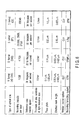
- FIG. 3 is a block diagram illustrating a general configuration of the optical disc device (disc drive) 200 shown in FIG. 1 or 2.
- the optical disc device 200 focuses laser light beams irradiated from an optical pick-up head (PUH) actuator 208 in an information recording layer of an optical disc 10 rotationally driven by means of a spindle motor 220 (adjusts a focus to a target recording layer by means of a focus servo control), thereby carrying out information recording/reproducing operation.
- the light beams reflected from the disc 10 (layer 0 and/or layer 1 thereof) pass through an optical system of the PUH 208 again, each of which is detected as an electrical signal by means of a photo detector (PD) 210.
- PD photo detector
- the detected electrical signal is amplified by means of a preamplifier 212, and the amplified signal is output to a servo circuit 218 and an RF signal processing circuit 214 and an address signal processing circuit 216.
- the servo circuit 218 generates servo signals such as focus, tracking, tilt, and rotation speed, and these servo signals are output to focus, tracking, and tilt actuators, although not shown, in the PUH 208, respectively.
- the rotation speed servo signal is sent to a driver circuit system of the spindle motor 220, and a linear speed of a laser beam spot on a disc recording layer is controlled at a predetermined value.
- the signal processing circuits 214 and 216 read record data or demodulate an address signal or the like.
- the demodulation method includes a slice system or a partial response maximum likelihood (PRML) system.
- the slice system includes: a method for binarizing a signal after linear waveform equalization has been carried out with respect to a reproduction signal and a method for binarizing a signal after equalization has been carried out by means of a nonlinear equalizer called a limit equalizer for limiting a high amplitude component in a low frequency area of a reproduction signal to a predetermined value.
- an optimal PR class for example, PR (1,2,2,2,1) or PR (1,2,1), PR (1,2,2,1), PR (3,4,4,3) or the like can be selected in response to frequency characteristics of a reproduction signal.
- the optical disc device 200 selects an optimal demodulating system (slice system or PRML system) in accordance with the optical disc 10 targeted for recording and reproducing operation and a size of a focus beam spot formed by the PUH 208.
- an optimal demodulating system slice system or PRML system
- the address signal processing circuit 216 processes a detected signal, thereby reading out "physical address information" indicating a recording location on an optical disc, and then, supplying the read out information to a controller 250.
- the controller 250 reads out data (such as user data) from a desired address location or record data to a desired address location, based on the address information.
- the record data is modulated into a recording waveform control signal suitable to optical disc recording by means of a recorded waveform circuit, although not shown, in a recording signal processing circuit 204 or a laser diode driver LDD (laser diode driver circuit) 206. Based on the thus modulated signal, the laser diode driver LDD 206 illuminates a laser diode, and then, records information in the optical disc 10 (information recording layer(s) of layer 0 and/or layer 1 shown in FIG. 4 or the like).
- the optical head PUH 208 incorporates one of single wavelength light sources having any one of wavelengths 405 ⁇ 15 nm, 650 ⁇ 20 nm, and 780 ⁇ 30 nm or a plurality of single wavelength light sources (refer to FIG. 13 described later).
- an objective lens used for focusing coherent laser light beams having the above described wavelengths on a recording layer of the optical disc 10 by means of the optical head PUH 208 has an NA value of 0.65 indicating the number of apertures in the present embodiment.
- an objective lens having an NA value of 0.65 is used.
- RIM Intensity a relative intensity at the periphery of an objective lens (in boundary location of an aperture portion) when a center intensity is defined as “1" is called “RIM Intensity”.
- a value of the RIM Intensity in the H format is set within the range of 55% to 70%.
- a wavefront aberration quantity in the optical head at this time is optically designed so as to be a maximum of 0.33 ⁇ (0.33 ⁇ or less) with respect to a use wavelength ⁇ .
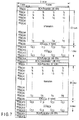
- FIG. 4 is an exemplary view illustrating a general configuration of a disc shaped multi-layered information recording medium (multi-format disc) according to an embodiment of the present invention.
- This example shows a twin format optical disc (hereinafter, referred to as TF disc) having two information recording layers in particular from among multi-format discs.
- the TF disc has two information recording layers (layer 0 and layer 1), as shown in FIG. 4. These layers are composed of different formats, file systems, or applications or are composed of discontinuous logic spaces.
- FIG. 5 is an exemplary view illustrating a layout example of layers of a twin format disc (TF disc).
- TF disc twin format disc
- This example shows a case in which layer 0 (L0 has a D format (standard DVD) and layer 1 (L1) has an H format (high density HD DVD) as layer formats.
- Other examples can include combinations of a case in which layer 0 has a B format (BF) and layer 1 has a D format (standard DVD), a case in which layer 0 has a D format (standard DVD) and layer 1 and layer 2 has an H format (HD_DVD).
- an information area of HD DVD allocated in layer 1 is divided into a BCA (Burst cutting area)-H area; a System Lead-in area-H area; a Data Lead-in area-H area; Data area-H area; and a data Lead-out area-H area from the inner periphery side of the disc 10.
- a BCA mark is recorded in advance due to a groove of a substrate of the disc 10, due to release of a reflection film, or due to a change of a recording medium.
- the BCA mark is modulated in a circumferential direction of the optical disc 10.
- This BCA mark is provided as a comb shaped mark on which identical items of information are arranged in a radial direction.
- a BCA code is recorded after modulated in accordance with an RZ modulation method.
- the BCA mark has the same shape in a radial direction, thus making it unnecessary to apply tracking and making it possible to reproduce information merely by applying a focus.
- the System Lead-in area-H area information is recorded in emboss pits.
- This information is provided as management information contained in the optical disc 10 such as disc identification information or capacity of the Data area-H area.
- the shortest mark length of the emboss pit in this area is set at a value which is twice as much as that in the Data area-H area.
- Data such as video image data or user data is recorded in the Data area-H area.
- signals are recorded at a density equal to that in the Data area-H area.
- These areas are used as overrun areas for tracking servo or the like.
- write-once type optical disc and in a rewritable type optical disc respectively, these areas each are used as a write-once or rewritable management information recording area.
- An information area in the D format (standard DVD) allocated in layer 0 is divided into a Lead-in area-D area, a Data area-D area, and a Lead-out area-D area from the inner periphery side of the disc 10.
- a BCA area is not allocated in layer 0 because optical interference between layers is significant in the BCA area, thus avoiding adverse influence of the BCA mark in layer 0 on reproduction of the BCA mark in layer 1.
- Disc identification information is recorded in the BCA mark, thus making it necessary for the optical disc device 200 to first reproduce BCA information. In this manner, the BCA mark is not allocated in layer 0, whereby a TF disc can be recognized at a high speed and with high reliability.
- Disc management information such as identification information on the disc 10 or capacity of the Data area-D area is recorded in the Lead-in area-D area.
- data such as video image data or user data is recorded in the Data area-D area.
- a signal is recorded at a density equal to that in the Data area-D area. This area is used as an overrun area for tracking servo or the like.
- this area is used as a write-once or rewritable management information recording area.
- a reflection factor of a twin format disc (TF disc) 10 according to the present embodiment.
- this TF disc 10 is monitored at a wavelength of 405 nm
- reflection factors of layer 0 and layer 1 each are included in the range of 14% to 32%.
- the reflection factor of layer 0 is 40% or more, and the reflection factor of layer 1 is lower than 14%.
- an existing DVD device automatically leads a focus into only layer 0 that is a standard (non-HD) DVD.
- FIG. 6 is an exemplary view illustrating an example of formats allocated in layers of a twin format disc (or multi-format disc).
- a twin format disc or multi-format disc.
- ROM type read-only type enabling only reproduction
- ⁇ R type write once type enabling only one information recording operation
- ⁇ RW type or RAM type rewritable type
- CLV of a rotation control system is an acronym for Constant Linear Velocity, and denotes a rotation control method in which the velocity in a linear direction is maintained to be constant.
- ETM Eight to Twelve Modulation
- EFM Eight to Fourteen Modulation
- LFMplus is provided as a system for converting an 8-bit information bit into 16 bits.
- 1-7pp (1-7 parity preserve) is provided as a conversion system for carrying out data conversion while a length of each data bit is restricted so as to be included between 2T being twice a basic channel length (T) and 8T being eight times thereof.
- a D format indicates an already common standard DVD format
- a C format indicates physical specification that is identical to that of a CD format.
- an H format and a B format each are provided as a format example of a next generation high density optical disc that enables information recording/reproducing operation with higher density.
- the former (H format) is called HD DVD
- the latter (B format) is called BF.
- FIG. 7 is an exemplary view showing a configuration of information recorded in a burst cutting area (BCA) provided in layer 1 of a twin format disc (or multi-format disc).
- the BCA data shown in FIG. 7 has two BCA preambles, two post-ambles, and two BCA data areas (illustrated Information area).
- a BCA error detection code EDCBCA and a BCA error correction code FCCBCA are added to BCA data areas, and a BCA concatenation area (illustrated BCA - Concatenation area) is allocated therebetween.
- sync bytes SBBCA or re-sync bytes RSBCA on one by one byte basis are inserted into every 4 bytes.
- the BCA preamble comprises 4 bytes, and all "00h” are recorded.
- sync bytes SBBCA are allocated immediately preceding each BCA preamble.
- 76 bytes are set in a BCA data area BCAA.
- a BCA post-amble comprises 4 bytes, and all repetition patterns of "55h” are recorded.
- a BCA concatenation area comprises 4 bytes, and all "AAh” are repeatedly recorded.
- FIG. 8 is an exemplary view illustrating an example of contents of information recorded in a burst cutting area (BCA).
- BCA data area illustrated Information area
- FTG. 7 one or plural items of information are recorded while a BCA record is defined as one unit.
- this record can include disc identification information or information for copy control.
- FIG. 8 shows an example of a BCA record that represents disc identification information. The first 2 bytes record a BCA record identifier representing what type of that BCA record (such as identification information or copy control information) is. Then, a version number of the BCA record indicating a format of the BCA record is recorded. Next, a data length for determining a size of the BCA record is recorded.
- a configuration can be provided so that this length does not include 4 bytes from a BCA record identifier that is a header of the BCA record to a data length.
- a 1-byte book type and a disc type are recorded.
- the book type is provided as an identifier indicating a disc format and a read-only, write once, and rewritable types or the like.
- FIG. 9 is an exemplary view illustrating a specific example of part (book type/disc type) of information recorded in a burst cutting area (BCA).
- information is allocated on 1 by 1 bit basis in 4 bits of disc type from among an information byte of book type/disc type.
- the most significant bits in the disc type stores a mark polarity representing whether a reflection factor of a recording mark (bit) is higher or lower than that of a non-mark (pit).
- a next bit stores a TF flag indicating whether or not that disc is a twin format disc (TF disc).
- this TF flag is binary 0
- binary 1 it indicates that the disc is a twin format disc.
- a multi-bit (2 or 3 bits) identifier is provided using next reserved bits, thereby making it possible to identify a multi-format optical disc having three layers or more.
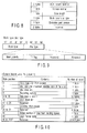
- FIG. 10 is an exemplary view illustrating a specific example of emboss pit information provided in a system lead-in area H of layer 1 in a twin format disc (or multi-format disc).
- book type/part version information is stored in the first byte location.
- the book type is provided as an identifier indicating a format of the disc 10 and a read-only type (ROM type), a write once type ( ⁇ R type), a rewritable type ( ⁇ RW type or RAM type) or the like.
- the part version is provided as version management information on that format.
- the disc size records information indicating a diameter of that disc 10. For example, 0000b is recorded for a 12 cm disc and 0001b is recorded for an 8 cm disc.
- a maximum transfer rate records a maximum transfer rate required to normally reproduce data recorded in a disc as required.
- a disc structure stores information indicating the number of layers in that format, information indicating a polarity as to whether or not a track is oriented from the inner periphery side to the outer periphery side in each layer or vice versa; and information indicating that the layer is of a read-only type, of a write once type, or of a rewritable type.
- the number of layers used here denotes the number of layers in a format instead of the number of layers which the disc 10 physically has.
- the recording density stores information indicating density and track pitches in a disc tangent direction.
- the data area allocation records a start address and an end address of Data area-H.
- the BCA descriptor records information indicating whether BCA exists or not.
- the extension part version records part version extension information.
- the maximum reading speed records a maximum linear speed required to normally read data recorded in a disc. Then, the layer format table records information described below.
- FIG. 11 is an exemplary view illustrating a specific example of a layer format table included in part of the emboss bit information shown in FIG. 10.
- this layer format table the most significant 2 bits are allocated in a reserved area, the next 3 bits are allocated as a format identifier of layer 1, and the further 3 bits are allocated as a format identifier of layer 0.
- an HD DVD-ROM format is allocated to 000b of layer 1
- an HD DVD-ROM format is allocated to 000b of layer 0.
- a DVD-ROM format is allocated to 100b of layer 1.
- a format indicated by a book type of that format may be allocated to 000b of layer 0 and/or layer 1.
- a format identifier of layer 0 may be set to 010b or the like.
- FIG. 12 is an exemplary view illustrating a specific example of emboss pit information provided in a lead-in area D of layer 0 of a twin format disc (or multi-format disc).
- the contents of bytes shown in FIG. 12 are basically identical to those of layer 1 shown in FIG. 10.
- a twin format disc descriptor is recorded in a byte location 128 instead of the table.
- the twin format disc descriptor is 00000000b
- a format defined by a book type is indicated.
- layer 0 is defined as DVD-ROM
- layer 1 is defined as HD DVD-ROM.
- the twin format disc descriptor may be set to 01000000b.
- FIG. 13 is an exemplary view illustrating a general configuration of an optical system for recording or reproducing information to/from layers of a twin format disc (or multi-format disc) by using laser light beams.
- FIG. 14 is an exemplary view illustrating another example of a general configuration (single beam multi-optical head or multi-lens/multi-beam single optical head) of an optical system for recording or reproducing information to/from layers of a twin format disc (or multi-format disc) by using laser light beams.
- One (or two) optical heads (PUH) for irradiating two laser beams to layers separately via two objective lenses OL0 and OL1 is used here.
- the twin format disc (TF disc) is formed in accordance with formats having different layers from each other.
- an optical disc device 200 enabling recording/reproducing operation in both layers (layer 0 and layer 1) has a function for properly switching a wavelength ⁇ (such as 405 nm, 650 nm, and 780 nm) of laser diodes (LD1 and LD2), aperture number NA of objective lens (such as 0.45, 0.60, 0.65, and 0.85), and/or a demodulation system (such as PRML system and slice system) in accordance with the respective formats.
- ⁇ such as 405 nm, 650 nm, and 780 nm
- NA of objective lens such as 0.45, 0.60, 0.65, and 0.85
- a demodulation system such as PRML system and slice system
- FIG. 15 is an exemplary view illustrating a specific example of specification (combination of laser wavelength, objective lens aperture number, and demodulation system or the like) of a disc device compatible with formats of a twin format disc (or multi-format disc).
- an optical disc device can automatically switch the laser or the like as required and can switch it in accordance with a command from a host.
- FIG. 15 shows a parameter example of a format used in the disc 10 targeted for carrying out such automatic switching and the optical disc device 200 compatible with formats.
- FIG. 16 is an exemplary view illustrating an example (dual layer disc which is not a twin format type) in which layers (L0* and L1*) are recorded in the same format, recording information (Data 0* and Data 1*) is physically divided into a plurality of layers, and recording information (Data 0* + Data 1*) is logically as one item of data.
- FIG. 16 shows a schematic view relating to exchange of information between the optical disc device 200 and the host device 300 in the case of reproducing the dual layer DVD-ROM disc which is not a twin format type.
- the optical disc device 200 converts the sector numbers into a list of logical sectors of one row.
- logical sector numbers are used. This system is featured in that there is no need for the host device 300 to discriminate whether or not "that disc has two layers or one layer" and in that processing is simple.
- the host device 300 provides an access without considering whether information to be read out exists in layer 0 (L0*) or layer 1 (L1*).
- a command for carrying out data readout at a high speed while layers overlap many times may be sent to the optical disc device 200.
- the optical disc device 200 there occurs a need for the optical disc device 200 to switch layers (L0* and L1*) frequently.
- the host device 300 cannot recognize a relationship between a logical sector and a layer simply, thus making it difficult to avoid such a situation (a situation in which data cannot be transmitted within a required time interval).
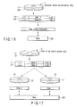
- FIG. 17 is an exemplary view illustrating an example in which recording information (Data 0 and Data 1) contained in layers (L0 and L1) is recorded in individual formats (may be identical to or different from each other) and recording information (Data 0 and Data 1) is physically and logically handled to be divided into a plurality of layers, i.e., an example (twin format dual layer disc 10) that physically corresponds to one dual layer disc and that logically corresponds to two individual single layer discs (virtual discs 1a and 1b).
- FIG. 17 shows a schematic view relating to exchange of information between the optical disc device 200 and the host device 300 in the case of reproducing a twin format disc.
- the optical disc device 200 converts physical sector numbers of layers (L0 and L1) into logical sector numbers on a layer by layer basis or on a format by format basis.
- This optical disc device notifies to the host device 300 that a plurality of discs (physically one multi-format disc) have been virtually inserted into the optical disc device 200.
- this virtual disc is called a physical volume (simply referred to as PV).
- physical volume numbers (such as PV0 and PV1) are allocated to the physical volumes, respectively. For example, layer 0 (L0) is converted into physical volume 0 (PV0), and layer 1 (L1) is converted into physical volume 1 (PV1).
- a drive configuring the optical disc device 200 notifies that "two physical volumes virtually exist", thereby making it possible for the host device 300 to explicitly read out information from either of the physical volumes or instruct whether or not to explicitly switch a physical volume to be read out.
- it is estimated in advance to take a predetermined amount of time to switch a physical volume.
- the host device 300 does not recognize an incompatible physical volume (B format shown in FIG. 6, for example), making it possible to issue a readout command to only compatible physical volumes (H format and D format, for example).
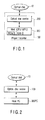
- FIG. 18 is a state transition chart illustrating a transition (example 1) of a reproduction state in an optical disc device (disc drive).
- the optical disc device 200 In the case where the optical disc device 200 is powered ON, the optical disc device 200 temporarily resets the setting of a recording/reproduction control program.
- the state of the disc in the optical disc device 200 enters an "empty" state.
- the optical disc device 200 starts loading of the optical disc 1.0 automatically or in accordance with a load command from the host device 300.
- the optical disc device 200 loads predetermined physical volume 0, and enters a state "PV0" that enables recording/reproducing operation of physical volume 0.
- the optical disc 200 is powered ON, in the case where the optical disc 10 has already been inserted, loading of physical volume 0 is carried out immediately after resetting.
- an eject button although not shown, of the optical disc device 200 has been pressed or in the case where an eject command has been issued from the host device 300, the optical disc device 200 ejects the optical disc 10 to outside of the optical disc device 200, and the disc state in the optical disc device 200 reverts to "empty".
- this host device 300 attempts to carry out recording/reproducing operation with respect to another physical volume, this host device 300 outputs a physical volume switching command to the optical disc device 200 in a state "PV0" in which physical volume 0 has been loaded.
- the optical disc device 200 switches a physical volume to be loaded.
- this optical disc device 200 changes a state in a state "'PV1" in which physical volume 1 has been loaded.
- the optical disc device 200 has a function for preferentially loading physical volume 0 as a default physical volume.
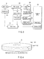
- FIG. 19 is a state transition chart illustrating a transition (example 2) of a reproduction state in an optical disc device (disc drive) on which a twin format disc (TF disc) has been loaded.
- the optical disc device 200 has a function for recognizing a DVD-ROM or a DVD video as physical volume 0 initially (by default). In this manner, even in the case where the optical disc device 200 according to the embodiment of the present invention is connected to the host device 300 comprising only a function for read-only commercially available DVD-ROM (DVD video), it becomes possible to normally reproduce only a DVD-ROM (DVD video) at the minimum.
- FIG. 20 is an exemplary view illustrating an example (a list of available commands) of commands possessed by an optical disc device (disc drive) that handles a twin format disc (or multi-format disc).
- An optical disc device has a function for, in the case where commands shown in a list of FIG. 20 (such as optical disc format command, optical disc management information readout command, optical disc management information write command, or optical disc recording/reproducing state change command) have been received from the host device 300, returning a response to the host device 300 in accordance with a predetermined format.
- this processing function is packaged as firmware of the optical disc device 200.
- the host device 300 has a function for issuing a command to the optical disc device 200, and then, operating the optical disc device 200, in accordance with the predetermined format.
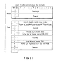
- FIG. 21 is an exemplary view illustrating an example of a response format to inquiry of disc management information, used in an optical disc device (disc drive) that handles a twin format disc (or multi-format disc).
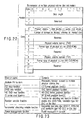
- FIG. 22 is an exemplary view illustrating an example of a format of transmitting disc management information, used in an optical disc device (disc drive) that handles a twin format disc (or multi-format disc).
- FIGS. 21 and 22 show a response format of "inquiring multiple physical volume disc information" that is a type of "inquiry of disc management information (refer to FIG. 20) and a format of "transmitting multiple physical volume disc information” that is a type of "transmission of disc management information (refer to FIG. 20)".
- the optical disc device 200 In the case where a command of "transmitting multiple physical volume disc information" has been issued, the optical disc device 200 carries out loading of "physical volume number loaded on optical disc device". However, in the case where the optical disc device 200 does not correspond to that number or the optical disc 10 does not correspond thereto, the optical disc device 200 returns an error to the host device 300.
- FIG. 23 is an exemplary view illustrating an example of functions (a list of applicable functions) possessed by an optical disc device (disc drive) that handles a twin format disc (or multi-format disc). Numbers are defined in advance for these functions that the optical disc device 200 has (processing function for multiple physical volume disc, DVD format playback function, HD DVD format playback function, BF format playback function, function for recording into random function enabling disc (such as DVD-RAM, rewritable type HD DVD), function for recording into sequential recording disc (such as DVD-R/-RW and HD DVD-R/-RW), and power management function or the like).
- the optical disc device 200 has a function for returning a list of commands available to the optical disc device 200 in response to inquiry from the host device 300. This function is mainly packaged as firmware of the optical disc device 200.
- FIGS. 24A and 24B are views each illustrating an example of response of an optical disc device (disc drive) that handles a twin format disc (or multi-format disc) in the case where inquiry of a configuration state has been issued from a host.
- the optical disc device 200 returns a list of functions available to the device itself (refer to FIG. 23) to the host device 300 (refer to FIG. 24A). Further, the optical disc device 200 sets a flag indicating a current state in response to a state of medium loaded at that time, as shown in FIG. 24B.
- the optical disc device 200 has a multiple PV function (processing function for multiple physical volume disc), and a twin format disc (TF disc) has been loaded as an optical disc 10, "1" is set at a multiple PV flag.
- TF disc twin format disc
- "1" is set at an HD DVD-ROM read flag.
- a flag is set to "0" with respect to a function relating to PV that is not loaded.
- the optical disc device 200 has a function for carrying out such a response, whereby the host device 300 can judge instantly that the disc 10 inserted into the optical disc device 200 is a multi-format optical disc and what a currently loaded format is. If the host device 300 is compatible with reproduction of a multi-format optical disc, it becomes possible to load a preferred physical volume by issuing a command for switching physical volume PV. In addition, after a desired physical volume has been temporarily loaded, information recording/reproducing operation relevant to the optical disc 10 can be smoothly carried out by issuing only a command compatible with respective formats.
- FIGS. 25A and 25B are views each illustrating an example of response of an optical disc device (disc drive) that handles a twin format disc (or multi-format disc) in the case where inquiry of a configuration state has been issued from a host compatible with only DVD reproduction.
- a shaded portion denotes a portion which a host device 300 compatible with only DVD reproduction does not recognize.
- the host device 300 does not make recognition of HD DVD, and thus, all of the commands associated with a function or a disc relevant to HD DVD are ignored.
- the host device 300 can judge that DVD-ROM is loaded in the case where a DVD-ROM disc has been inserted.
- the optical disc device 200 first loads DVD-ROM of physical volume 0.
- the host device 300 recognizes that DVD-ROM has been loaded, making it possible to reproduce DVD-ROM smoothly without any problem.
- the optical disc device 200 according to the embodiment of the present invention has a feature that the disc device operates smoothly without any problem with respect to the host device 300 commercially available.
- FIGS. 26A and 26B are views each illustrating an example of response of an optical disc device (disc drive) "compatible with only general DVD", which cannot handle a twin format disc (or multi-format disc) in the case where inquiry of a configuration state has been issued from the host.
- a multiple PV flag and an HD DVD read flag are assigned to reserved bits in a device compatible with only DVD.
- the optical disc device 200 does not have a reproduction function of HD DVD-ROM, and thus, this disc device does not return this flag.
- the host device 300 can check that the optical disc device 200 during communication does not have a function for reproducing a TF disc.
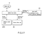
- FIG. 27 is an exemplary view illustrating an optical disc device (disc drive) that has a function for switching a default physical volume.
- an optical disc device disc drive
- FIG. 27 is an exemplary view illustrating an optical disc device (disc drive) that has a function for switching a default physical volume.
- physical volume 0 is preferentially loaded as a default physical volume.
- the host device 300 compatible with only HD DVD when the DVD disc 10 is first loaded, there occurs a need for switching a physical volume from DVD to HD DVD prior to recording and reproducing operation every time.
- the optical disc device 200 shown in FIG. 27 can be compatible with various types of host device 300PC (or 300).
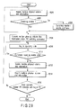
- FIG. 28 is a flow chart illustrating an example of a method for reproducing a multi-format disc (twin format disc).
- This example shows a processing operation viewed from the host device 300 in the case of reproducing a multi-format optical disc 10.
- a description will be given with respect to a case in which a TF disc including DVD-ROM and HD DVD-ROM or DVD-ROM, HD DVD-ROM or other disc has been inserted as a multi-format optical disc 10.
- the host device 300 After the corresponding optical disc device 200 has been powered ON, the host device 300 periodically executes a check of whether or not the disc 10 is inserted. Here, after confirming that the disc 10 has been inserted into the optical disc device 200, the host device 300 issues "configuration state inquiry (refer to FIG. 20)" (block #100), and checks a list name (profile: refer to FIG. 23) of functions available to the optical disc 10 and the optical disc device 200 at a current time point.
- the host device 300 checks the contents of that flag bit. In the case where the flag bit has been set to 0b (block #108: No), it is determined that the inserted disc 10 is not a multi-format optical disc, and a current processing operation moves to a processing operation for reproducing one format currently loaded. In the case where the flag bit has been set to 1b (block #108: Yes), the host judges that the inserted disc is a multi-format optical disc.
- the host device 300 issues a command for inquiring disc management information (block #110). Then, a drive of the optical disc device 200 notifies: the number of physical volumes of the inserted optical disc 10; type of format of the respective physical volumes; and the currently loaded physical volume number (block #112). Immediately after the disc 10 has been inserted, the format of physical volume 0 is loaded. If a user's reproduction request is made or if a format defined so that the host device 300 carries out recording/reproducing operation has been loaded in advance (block #114: No), the host device 300 issues a command to that format, and starts recording and reproducing operation of an optical disc. On the other hand, in the case where the format has been a format different from that of the user's request (block #114: Yes), the host device 300 starts switching of a physical volume.
- the host device 300 (or 300PC) is an HD DVD-ROM compatible software player or hardware player.
- the host device 300 in general, in the case where the user has inserted a TF disc of HD DVD-ROM/DVD-ROM, there is often a case in which an attempt is made to preferentially reproduce HD DVD-ROM containing a large amount of information. Therefore, while a drive of the optical disc device 200 first loads DVD-ROM that is a default physical volume, the host device 300 can be configured so as to have a function for switching to HD DVD-ROM a physical volume loaded immediately after acquisition of multiple physical volume disc information, and then, notifying to the user a result of reproduction of HD DVD-ROM. By doing this, it becomes possible to show the user as if HD DVD-ROM were preferentially reproduced.
- this host device 300 it is possible to set a default physical volume apart from the optical disc device 200.
- this host device 300 has a function for switching this default physical volume in response to the user's request.
- this volume switching function is packaged as application software, and the function is presented to the user as a software button.
- this volume switching function is packaged as firmware of the optical disc device 200, and the function is presented to the user as a switch display using an on-screen display.
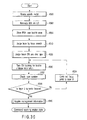
- FIG. 29 is a flow chart illustrating an example of a method for switching a physical volume in a multi-format disc (twin format disc).
- This example shows a flow chart of an operation for switching a physical volume of a multi-format optical disc viewed from the host device 300.
- the host device 300 carries out inquiry of multiple physical volume disc information to the optical disc device 200 (block #200).
- the number of physical volumes; type of format of the physical volumes; and the currently loaded physical volume number are checked (block #112).
- a state of the optical disc device 200 is not a physical volume switching disable state (block #202: No)
- a switching/ejection enable command is used to switch the state of the optical disc device 200 to a switching enable state (block #204).
- block #204 or where the state of the optical disc device 200 has been set at a physical volume switching disable state block #202: Yes
- multiple physical volume disc information transmission is used to issue a command for switching a loading operation into a desired physical volume (block #206).
- the host device 300 periodically carries out inquiry of an operating state (block #208).
- the optical disc device 200 switches a physical volume to be loaded in accordance with a command from the host device 300
- a predetermined amount of time for switching a laser diode (LD) or re-leading of a focus servo or a tracking servo or the like is required for this switching operation.
- the optical disc device 200 notifies that the disc device is in operation in response to inquiry from the host device 300.
- the host device 300 makes periodic inquiry, the host waits until a response from the optical disc device 200 is set in a "command receiving enable state" (Loop of "No" in block #210).
- command receiving is enabled (block #210: Yes)
- inquiry of multiple physical volume disc information is carried out (block #212), and then, a currently loaded multiple physical volume is checked (block #214).
- the number and type of the currently loaded multiple physical volume coincide with the target (block #216: Yes)
- the switching of the physical volume is completed.
- a processing operation for multiple physical volume information acquisition (block #200) or switching command (block #206) is carried out again.
- FIG. 30 is a flow chart illustrating an example in the case where an optical disc device (disc drive) carries out loading of a physical volume of a multi-format disc (twin format disc).
- the optical disc device 200 starts rotation of the spindle motor 220 (block #300), and then, illaminates a laser diode (LD) (block #302).
- LD laser diode
- the wavelength of 650 nm is selected. This is because, in the case of reproducing a DVD-R disc at the wavelength of 405 nm, an optical focus spot becomes smaller than the wavelength of 650 nm and energy density increases, and thus, there is a danger that already record data is destroyed.
- the optical disc device 200 then carries out feeding of an optical head (PUH), and moves the PUH actuator 208 to the inner periphery side of the disc 10 (block #304).
- the PUH actuator 208 is moved vertically in a focus direction, and a layer judgment is carried out (block #310).
- a focus is turned ON.
- a type of the disc 10 is judged in accordance with the frequency characteristics of a tracking signal, a BCA signal, and an RF signal or the presence or absence of these signals (block #320). Based on a result of the judgment, a focus is led into layer 0.
- the optical disc device 200 checks that layer 0 is reproduced in accordance with ID information and physical address information or the like of the optical disc 10 (block #336: Yes), and then, carries out acquisition of further detailed management information (block #340). Then, optical disc loading is completed.
- the disc 10 being reproduced is a TF disc as shown in FIG. 5
- a format of layer 0 of a disc to be reproduced and a format of layer 1 can be checked based on a twin format disc descriptor and book type or part version information.
- the optical disc device 200 enters a state in which a multiple PV flag, an HD DVD read flag, and a DVD read flag can be returned in response to a configuration state inquiry or the like from the host device 300.
- a focus jump is carried out (block #334), and focus leading into layer 0 is carried out.
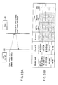
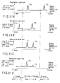
- FIGS. 31A to 31D show a flow illustrating an example of a layer judging method in a multi-format disc (twin format disc). Now, a detailed description will be given with respect to a layer judgment using a focus search.
- an objective lens OL of the PUH 208 is made close to the optical disc 10
- signals as shown in FIGS. 31A to 31D can be obtained.
- the reproduction signal increases when a focus is adjusted to an information recording layer of the optical disc 10.
- a disc type can be judged based on locations (Pla to P1d and P2a to P2d) and intensity (relative scale of signal level) of the signal peaks.
- an information recording layer of a B format (refer to FIG. 6) in which substrate thickness at a light incidence side is thinnest (0.1 mm) is present in the most frontal location (at the light receiving face side of optical disc), and thus, this format first has a peak (refer to P1b of area 1 shown in FIG. 31B).
- the HD DVD format and the DVD format each have a peak in identical location (location in the order of 0.6 mm from substrate surface) (refer to area 2 shown in FIGS. 31C and 31D).
- a CD format has a peak in location that is the most distant from a substrate at the light incidence side (1.0 mm to 1.2 mm) (refer to Pla of area 3 shown in FIG. 31A). Therefore, in location having a peak of the CD format, an objective lens becomes the closest to a substrate surface of the disc.
- the peaks of layers are substantially equal to each other (refer to P1c and P2c of area 2 shown in FIG. 31C).
- the peak levels of the layers become unbalanced due to an effect of a medium material for the layers (refer to P1d and P2d of area 2 shown in FIG. 31D).
- Unbalanced peaks in reproduction level are produced because a dual layer/twin disc designed for a 405 nm laser is subjected to focus search by 650 nm laser. In the case of using the 405 nm laser, unbalanced peaks cannot be substantially produced. Although an example of using a 650 nm laser has been shown here, this example does not show that the 405 nm laser cannot be used.
- the current step moves to the step of carrying out switching of an LD (switching into another wavelength laser) or switching of an objective lens (switching into another aperture number).
- a focus is lead into the optical disc 10, and the type of the optical disc 10 is judged based on that reproduction signal.
- a focus is carried out in layer 0, and it is determined whether layer 0 is DVD or HD DVD depending on the presence or absence of a tracking signal, the presence or absence of BCA information, and the presence or absence of an RF signal.
- the current step moves to the step of turning ON tracking relevant to next lead-in emboss information.
- the current step moves to the step of carrying out switching of an LD or an objective lens.
- a disc has a lead-in area at an inner periphery portion of the disc, and has a plurality of information recording layers between the inner periphery portion and an outer periphery portion of the disc.
- the lead-in area includes information (layer format table) indicating a format of each of a plurality of information recording layers (layer 1 and layer 0), and identifies a type (such as HD DVD-ROM format or DVD-ROM format) of a format used in each of the plurality of information recording layers (layer 0 and layer 1) in accordance with information indicating each of the formats (format of layer 1 and format of layer 0).
- the multi-format disc 10 includes a first layer (L0) for recording first data (Data 0) and a second layer (L1) for recording second data (Data 1) sequentially from the side close to the light receiving face of the optical disc 10 by way of example of a twin format disc (TF disc).
- Types of formats used here include a first format (for example, HD DVD-ROM format) and a second format (for example, DVD-ROM format).
- Information indicating formats (format information on layer 1 and format information on layer 0) includes a first information bit (000b shown in FIG. 11) indicating a first format (HD DVD-ROM format) and a second information bit (100b shown in FIG. 11) indicating a second format (DVD-ROM format).
- the first information bit (000b shown in FIG. 11) can indicate that the first data (Data 0) of the first layer (L0) conforms to either the first format (HD DVD-ROM format) or the second format (DVD-ROM format), and the second information bit (100b shown in FIG. 11) can indicate that the second data (Data 1) of the second layer (L1) conforms to either the first format (HD DVD-ROM format) or the second format (DVD-ROM format).
- a lead-in area (lead-in area D shown in FIG. 5) in the first layer (L0) can include information (twin format flag shown in FIG. 12) indicating a case in which formats of the plurality of information recording layers (layer 1 and layer 0) are different from each other
- a lead-in area (lead-in area H shown in FIG. 5) in the second layer (L1) can include information (layer format table shown in FIG. 11) indicating formats of a plurality of information recording layers (layer 1 and layer 0).
- a reproduction signal level obtained via an optical head is represented by variable P
- a reproduction signal level from the first layer (L0) is denoted by P1
- a reproduction signal level from the second layer (L1) is denoted by P2.
- a light receiving face location of an optical disc is defined as a reference
- two different predetermined variables x1 and x2 are defined, a combination state of the first format (for example, HD DVD-ROM format) and a second format (for example, DVD-ROM format) in an optical disc can be judged depending on whether or not the reproduction signal levels P1 and/or P2 are (is) between x1 and x2 (refer to FIGS. 31A to 31D).
- format types of the first layer (L0) and the second layer (L1) can be discriminated depending on whether or not the reproduction signal level P1 is obtained as a signal level different from the reproduction signal level P2 (refer to FIGS. 31C and 31D.
- an information recording medium recording/reproducing method for recording/reproducing information with respect to a multi-layered information recording medium (reference numeral 10 in FIG. 17, for example) having a plurality of information recording layers (L0 and L1), and then, transmitting/receiving information between the host device 300 and an information recording medium
- information recorded in the multi-layered information recording medium is divided into a plurality of information (data 0 and data 1), whereby transmission/receiving of information (data 0 and 1) contained in the host device 300 and the information recording medium can be carried out while the plurality of information are defined as information contained in a plurality of media (1a and 1b).
- an information recording medium recording/reproducing method for recording/reproducing information with respect to a multi-layered information recording medium (reference numeral 10 in FIG. 4, for example) having a plurality of information recording layers (L0 and L1), and then, transmitting/receiving information between the host device 300 and an information recording medium
- a first step of acquiring format information (refer to FIG. 6) contained in all information recording layers possessed by the information recording medium from one or more of information recording layers (for example, BCA-H, System Lead-in area-H, and Data Lead-in area-H of L1 shown in FIG.
- an information recording medium recording/reproducing method for recording/reproducing information with respect to a multi-layered information recording medium having a plurality of information recording layers (L0 and L1), and then, transmitting/receiving information between the host device 300 and an information recording medium, in the case where one of a plurality of information recording layers conforms to a commercially available format (for example, DVD video), and the other one conforms to a format (for example, HD DVD) available later than the commercially available format, a layer in which information is read out in the step of acquiring format information (FIG. 6) contained in all information recording layers possessed by the information recording medium can conform to the commercially available format (DVD video).
- a commercially available format for example, DVD video
- a format information recording layers possessed by the information recording medium can conform to the commercially available format (DVD video).
- an information management method for managing information by (a host) transmitting/receiving information between an information recording medium recording/reproducing apparatus 200 and an information recording medium the recording/reproducing apparatus recording/reproducing information with respect to a multi-layered information recording medium 10 having a plurality of information recording layers (L0 and L1), it is checked whether or not the information recording medium recording/reproducing apparatus 200 has means (firmware) for returning information (data 0, data 1 in FIG.
- a disc shaped multi-layered information recording medium comprising a lead-in area formed at an inner periphery portion; and information recording layers between the inner periphery portion and an outer periphery portion, wherein the lead-in area records information indicating a format of each of the information recording layers, and is configured so that a type of a format used in each of the information recording layers is identified in accordance with the information indicating the format.
- a recording method using a disc shaped multi-layered information recording medium which comprises a lead-in area formed at an inner periphery portion; and information recording layers between the inner periphery portion and an outer periphery portion, wherein the lead-in area records information indicating a format of each of the information recording layers, and is configured so that a type of a format used in each of the information recording layers is identified in accordance with the information indicating the format, the method comprising recording information in one of the information recording layers; and recording another information in another one of the information recording layers.
- a reproducing method using a disc shaped multi-layered information recording medium which comprises a lead-in area formed at an inner periphery portion; and information recording layers between the inner periphery portion and an outer periphery portion, wherein the lead-in area records information indicating a format of each of the information recording layers, and is configured so that a type of a format used in each of the information recording layers is identified in accordance with the information indicating the format, the method comprising reproducing information from one of the information recording layers; and reproducing another information from another one of the information recording layers.
- an reproducing apparatus using a disc shaped multi-layered information recording medium which comprises a lead-in area formed at an inner periphery portion; and information recording layers between the inner periphery portion and an outer periphery portion, wherein the lead-in area records information indicating a format of each of the information recording layers, and is configured so that a type of a format used in each of the information recording layers is identified in accordance with the information indicating the format, the apparatus comprising a first reproduction unit which reproduces information from one of the information recording layers; and a second reproduction unit which reproduces another information from another one of the information recording layers.
- a disc drive device using an optical disc which comprises a lead-in area formed at an inner periphery portion; and information recording layers between the inner periphery portion and an outer periphery portion, wherein the lead-in area records information indicating a format of each of the information recording layers, and is configured so that a type of a format used in each of the information recording layers is identified in accordance with the information indicating the format, the device comprising an optical system which accesses to each of the information recording layers by using a laser light beam; and a unit which records or reproduces information based on a type of a format used in each of the information recording layers via the optical system.
- the information recording medium comprises an optical disc in which information is record or reproduced by means of a laser beam via an optical head.
- the information recording layers includes a first layer which records first data and a second layer which records second data, the first layer and the second layer being sequentially arranged from a side close to a light receiving face of the optical disc.
- the type of the format includes a first format and a second format.
- the information indicating the format includes a first information bit indicating the first format and a second information bit indicating the second format. The first information bit indicates that the first data on the first layer is either the first format or the second format. The second information bit indicates that the second data on the second layer is either of the first format and the second format.
- the lead-in area in the first layer records information indicating that a format of each of the information recording layers is different from each another, and the lead-in area in the second layer records information indicating a format of each of the information recording layers.
- a reproduction signal level obtained via the optical head is represented by a variable P
- a reproduction signal level from the first layer is defined as P1
- a reproduction signal level from the second layer is defined as P2
- a light receiving face location of the optical disc is defined as a reference
- two different predetermined variables x1 and x2 are defined, a combination state of the first format and second format in the optical disc is discriminated depending on whether or not the reproduction signal levels P1 and/or P2 are between the x1 and x2.
- reproduction signal levels P1 and P2 are between the x1 and x2, types of formats of the first layer and the second layer are discriminated in accordance with whether or not the reproduction signal level P1 is a signal level which is different from the reproduction signal level P2.
- an information recording or reproducing method for recording or reproducing information with respect to a multi-layered information recording medium having information recording layers, and transmitting or receiving recording/reproducing information between a host device, the method comprising dividing the recording/reproducing information into items of information; and transmitting or receiving the items of the information as recording/reproducing information of virtual media between the host device.
- an information recording or reproducing method for recording or reproducing information with respect to a multi-layered information recording medium having information recording layers, and transmitting or receiving recording/reproducing information between a host device, the method comprising a first step of acquiring format information of all information recording layers from one or more of the information recording layers; a second step of notifying the acquired format information to the host device as information of virtual media; and a step of, after terminating the first and second steps, first starting recording/reproducing operation of the one or more of the information recording layers after there has been issued a command for recording/reproducing information with respect to an information recording layer other than the one or more of the information recording layers in which readout is currently being carried out from the host device.
- the one or more of the information recording layers includes the second information recording layer.
- an information management method for managing information by transmitting or receiving recording/reproducing information with respect to a multi-layered information recording medium having information recording layers between an information recording/reproducing apparatus, the method comprising checking whether or not the information recording/reproducing apparatus has means for returning information of virtual media; and in the case where it has been checked that the information recording/reproducing apparatus has the means for returning information of virtual media, and information recording/reproducing operation is carried out with respect to each one of the virtual media, issuing a command so as to execute switching of a medium with respect to the information recording/reproducing apparatus prior to carrying out the information recording/reproducing operation.
Landscapes
- Engineering & Computer Science (AREA)
- Signal Processing (AREA)
- Multimedia (AREA)
- Optical Recording Or Reproduction (AREA)
- Signal Processing For Digital Recording And Reproducing (AREA)
Applications Claiming Priority (1)
| Application Number | Priority Date | Filing Date | Title |
|---|---|---|---|
| JP2005211467A JP2007026617A (ja) | 2005-07-21 | 2005-07-21 | 情報記憶媒体、記録方法、再生方法および装置 |
Publications (2)
| Publication Number | Publication Date |
|---|---|
| EP1746597A2 true EP1746597A2 (fr) | 2007-01-24 |
| EP1746597A3 EP1746597A3 (fr) | 2008-06-04 |
Family
ID=37092519
Family Applications (1)
| Application Number | Title | Priority Date | Filing Date |
|---|---|---|---|
| EP06117379A Withdrawn EP1746597A3 (fr) | 2005-07-21 | 2006-07-18 | Méthode et appareil d'enregistrement de formats différents sur un disque optique multicouches |
Country Status (6)
| Country | Link |
|---|---|
| US (1) | US20070019533A1 (fr) |
| EP (1) | EP1746597A3 (fr) |
| JP (1) | JP2007026617A (fr) |
| KR (1) | KR100789854B1 (fr) |
| CN (1) | CN1901074A (fr) |
| TW (1) | TW200741674A (fr) |
Cited By (4)
| Publication number | Priority date | Publication date | Assignee | Title |
|---|---|---|---|---|
| EP2166538A1 (fr) * | 2008-09-23 | 2010-03-24 | Thomson Licensing | Procédé utilisant des informations de codage d'informations de données dans un support de stockage et support de stockage correspondant |
| EP2221812A3 (fr) * | 2006-06-02 | 2011-01-05 | Kabushiki Kaisha Toshiba | Support d'enregistrement optique, procédé d'enregistrement d'informations, et procédé de lecture d'informations |
| EP2290644A3 (fr) * | 2009-08-28 | 2011-03-30 | Hitachi Consumer Electronics Co., Ltd. | Disque optique, appareil de reproduction de disque optique, appareil à disque optique, procédé de reproduction et procédé d'enregistrement |
| EP2544183A4 (fr) * | 2010-03-05 | 2013-07-31 | Hitachi Consumer Electronics | Disque optique, dispositif de disque optique, procédé d'enregistrement d'informations et procédé de reproduction d'informations |
Families Citing this family (18)
| Publication number | Priority date | Publication date | Assignee | Title |
|---|---|---|---|---|
| US20090310464A1 (en) * | 2006-12-18 | 2009-12-17 | Mempile Inc. | Three-dimensional optical information carrier |
| JP2008159203A (ja) * | 2006-12-26 | 2008-07-10 | Tdk Corp | 光記録媒体、光記録媒体の記録再生方法 |
| JP2008293592A (ja) * | 2007-05-24 | 2008-12-04 | Toshiba Corp | 情報記録再生装置及び情報記録再生方法 |
| JPWO2009044725A1 (ja) * | 2007-10-01 | 2011-02-10 | シャープ株式会社 | 情報記録媒体、記録再生装置、および情報記録方法 |
| US7991949B2 (en) * | 2007-10-12 | 2011-08-02 | Microsoft Corporation | Embedded virtual media |
| KR100933859B1 (ko) | 2007-11-29 | 2009-12-24 | 주식회사 하이닉스반도체 | 플래시 메모리 소자 및 그것의 프로그램 방법 |
| WO2009119587A1 (fr) * | 2008-03-27 | 2009-10-01 | 日本電気株式会社 | Dispositif de lecture de disque optique |
| KR100982520B1 (ko) * | 2008-09-10 | 2010-09-16 | 삼성전자주식회사 | 광디스크, 광디스크에 대한 기록/재생 방법 및 장치 |
| JP5238436B2 (ja) | 2008-09-30 | 2013-07-17 | 株式会社日立製作所 | 光ディスク記録装置、光ディスク再生装置、情報記録方法および情報再生方法 |
| JP4567807B2 (ja) * | 2009-01-16 | 2010-10-20 | シャープ株式会社 | 光情報記録媒体 |
| JP4673413B2 (ja) * | 2009-02-27 | 2011-04-20 | シャープ株式会社 | 情報記録媒体 |
| JP5241569B2 (ja) | 2009-03-05 | 2013-07-17 | 株式会社日立製作所 | 光ディスク記録装置、光ディスク再生装置、情報記録方法および情報再生方法 |
| EP2455938A4 (fr) * | 2009-07-17 | 2014-06-25 | Sharp Kk | Support d'enregistrement d'informations optiques |
| JP2011070709A (ja) * | 2009-09-24 | 2011-04-07 | Hitachi-Lg Data Storage Inc | 光ディスク、光ディスク装置、再生方法及び記録方法。 |
| KR20120049945A (ko) * | 2009-11-06 | 2012-05-17 | 파이오니아 가부시키가이샤 | 정보 기록 매체, 정보 기록 장치 및 정보 재생 장치 |
| JP5147879B2 (ja) | 2010-03-05 | 2013-02-20 | 日立コンシューマエレクトロニクス株式会社 | 光ディスク、光ディスク装置、情報記録方法、および情報再生方法 |
| JP4976523B2 (ja) * | 2010-06-14 | 2012-07-18 | シャープ株式会社 | 情報再生方法 |
| KR20140060455A (ko) * | 2012-11-07 | 2014-05-20 | 삼성전자주식회사 | 광디스크 및 이를 재생하는 광디스크 재생장치 |
Citations (2)
| Publication number | Priority date | Publication date | Assignee | Title |
|---|---|---|---|---|
| JP2004206849A (ja) | 2002-01-22 | 2004-07-22 | Matsushita Electric Ind Co Ltd | 情報記録媒体、記録装置、再生装置、記録方法、再生方法 |
| JP2004355714A (ja) | 2003-05-29 | 2004-12-16 | Ricoh Co Ltd | 記録媒体ドライブ装置、記録媒体ドライブ用プログラム、記憶媒体及び記録媒体ドライブ方法 |
Family Cites Families (24)
| Publication number | Priority date | Publication date | Assignee | Title |
|---|---|---|---|---|
| CN1132185C (zh) * | 1994-12-19 | 2003-12-24 | 皇家菲利浦电子有限公司 | 多层记录载体和扫描该载体的装置 |
| US6151442A (en) * | 1996-07-08 | 2000-11-21 | Victor Company Of Japan, Ltd. | Signal compressing apparatus |
| US6240054B1 (en) * | 1996-05-15 | 2001-05-29 | Pioneer Electronic Corporation | Multiple layer disk reproducing apparatus, and apparatus for reproducing information record medium |
| JP3707137B2 (ja) * | 1996-07-04 | 2005-10-19 | ソニー株式会社 | 記録媒体、再生装置 |
| KR100255191B1 (ko) * | 1997-12-31 | 2000-06-01 | 윤종용 | 광 디스크 재생장치에서 종류 검출을 위한 디스크와그 종류 검출방법 |
| JP3638077B2 (ja) * | 1998-01-20 | 2005-04-13 | 富士通株式会社 | パワーセーブモード制御方法及び記憶装置 |
| JPH11232836A (ja) * | 1998-02-12 | 1999-08-27 | Toshiba Corp | 多層情報層を有する情報記憶媒体及び多目的情報処理装置 |
| DE19859035A1 (de) * | 1998-12-21 | 2000-06-29 | Thomson Brandt Gmbh | Gerät zum Lesen oder Schreiben optischer Aufzeichnungsträger mit unterschiedlichen Informationsträgerschichten |
| KR100694410B1 (ko) * | 2000-03-30 | 2007-03-12 | 엘지전자 주식회사 | 다층 광디스크 및 그 구동방법 |
| TWI236667B (en) * | 2000-06-29 | 2005-07-21 | Samsung Electronics Co Ltd | Optical recording medium having read-only storage area and writeable storage area and recording/reproducing apparatus and method therefor |
| US20040156294A1 (en) * | 2001-04-17 | 2004-08-12 | Katsuya Watanabe | Optical disc, information recording/reproducing method and information recording/reproducin apparatus using the same |
| KR20030060650A (ko) * | 2002-01-10 | 2003-07-16 | 엘지전자 주식회사 | 광디스크 장치에서의 다층 디스크 재생방법 |
| JPWO2003063149A1 (ja) * | 2002-01-21 | 2005-05-26 | 松下電器産業株式会社 | 光ディスク装置及び光ディスク判別方法 |
| EP1469463B1 (fr) * | 2002-01-23 | 2009-06-17 | Panasonic Corporation | Unite de disque optique |
| KR100881665B1 (ko) * | 2002-05-31 | 2009-02-06 | 삼성전자주식회사 | 다층의 광 정보 저장매체 및 그 기록/재생 방법 |
| KR100915872B1 (ko) * | 2002-06-07 | 2009-09-07 | 엘지전자 주식회사 | 고밀도 멀티 레이어 광디스크와, 그에 따른 기록층별데이터 기록방법 |
| KR100925213B1 (ko) * | 2002-06-07 | 2009-11-06 | 엘지전자 주식회사 | 고밀도 멀티 레이어 광디스크와, 그에 따른 광 파워조절방법 |
| KR20030094855A (ko) * | 2002-06-08 | 2003-12-18 | 엘지전자 주식회사 | 고밀도 멀티 레이어 광디스크와, 그에 따른 포맷팅관리방법 |
| ATE485584T1 (de) * | 2002-08-22 | 2010-11-15 | Lg Electronics Inc | Hochdichter optischer datenträger und aufnahme- /wiedergabe verfahren dafür |
| JP2004139708A (ja) * | 2002-10-21 | 2004-05-13 | Sanyo Electric Co Ltd | 光ディスク装置 |
| JP3734816B2 (ja) | 2003-03-25 | 2006-01-11 | 株式会社リコー | 光情報記録装置、光情報記録媒体、光情報記録方法、プログラム、及び記憶媒体 |
| US7564760B2 (en) * | 2003-07-09 | 2009-07-21 | Lg Electronics, Inc. | Recording medium, method of configuring disc control information thereof, recording and reproducing method using the same, and apparatus thereof |
| JP2005166096A (ja) * | 2003-11-28 | 2005-06-23 | Toshiba Corp | 光ディスク、光ディスク装置、光ディスク記録再生方法、bcaコード記録装置及びbcaコード記録方法 |
| KR20070003513A (ko) * | 2005-06-30 | 2007-01-05 | 엘지전자 주식회사 | 기록매체 및 기록매체 기록/재생방법 및 장치 |
-
2005
- 2005-07-21 JP JP2005211467A patent/JP2007026617A/ja active Pending
-
2006
- 2006-07-18 TW TW095126262A patent/TW200741674A/zh unknown
- 2006-07-18 US US11/488,040 patent/US20070019533A1/en not_active Abandoned
- 2006-07-18 EP EP06117379A patent/EP1746597A3/fr not_active Withdrawn
- 2006-07-21 CN CNA2006101035588A patent/CN1901074A/zh active Pending
- 2006-07-21 KR KR1020060068483A patent/KR100789854B1/ko not_active Expired - Fee Related
Patent Citations (2)
| Publication number | Priority date | Publication date | Assignee | Title |
|---|---|---|---|---|
| JP2004206849A (ja) | 2002-01-22 | 2004-07-22 | Matsushita Electric Ind Co Ltd | 情報記録媒体、記録装置、再生装置、記録方法、再生方法 |
| JP2004355714A (ja) | 2003-05-29 | 2004-12-16 | Ricoh Co Ltd | 記録媒体ドライブ装置、記録媒体ドライブ用プログラム、記憶媒体及び記録媒体ドライブ方法 |
Cited By (7)
| Publication number | Priority date | Publication date | Assignee | Title |
|---|---|---|---|---|
| EP2221812A3 (fr) * | 2006-06-02 | 2011-01-05 | Kabushiki Kaisha Toshiba | Support d'enregistrement optique, procédé d'enregistrement d'informations, et procédé de lecture d'informations |
| US8509049B2 (en) | 2006-06-02 | 2013-08-13 | Kabushiki Kaisha Toshiba | Optical recording medium having intermediate layer of prescribed thickness and thickness range for use with 405nm laser |
| EP2166538A1 (fr) * | 2008-09-23 | 2010-03-24 | Thomson Licensing | Procédé utilisant des informations de codage d'informations de données dans un support de stockage et support de stockage correspondant |
| EP2166539A1 (fr) * | 2008-09-23 | 2010-03-24 | Thomson Licensing | Procédé utilisant des informations de codage d'informations de données dans un support de stockage et support de stockage correspondant |
| EP2290644A3 (fr) * | 2009-08-28 | 2011-03-30 | Hitachi Consumer Electronics Co., Ltd. | Disque optique, appareil de reproduction de disque optique, appareil à disque optique, procédé de reproduction et procédé d'enregistrement |
| US8289822B2 (en) | 2009-08-28 | 2012-10-16 | Hitachi-Lg Data Storage, Inc. | Optical disc reproducing apparatus for implementing an optical recording and reproducing method for multi-layer optical discs |
| EP2544183A4 (fr) * | 2010-03-05 | 2013-07-31 | Hitachi Consumer Electronics | Disque optique, dispositif de disque optique, procédé d'enregistrement d'informations et procédé de reproduction d'informations |
Also Published As
| Publication number | Publication date |
|---|---|
| KR100789854B1 (ko) | 2008-01-02 |
| JP2007026617A (ja) | 2007-02-01 |
| US20070019533A1 (en) | 2007-01-25 |
| CN1901074A (zh) | 2007-01-24 |
| TW200741674A (en) | 2007-11-01 |
| KR20070012258A (ko) | 2007-01-25 |
| EP1746597A3 (fr) | 2008-06-04 |
Similar Documents
| Publication | Publication Date | Title |
|---|---|---|
| EP1746597A2 (fr) | Méthode et appareil d'enregistrement de formats différents sur un disque optique multicouches | |
| US20050128917A1 (en) | Optical disk, optical disk apparatus, optical disk recording and reproduction method, and apparatus and method for recording BCA code | |
| JP5705759B2 (ja) | 多層記憶媒体のデアイシング | |
| EP1607970B1 (fr) | Dispositif d'enregistrement d'informations, procede d'enregistrement d'informations, programme d'enregistrement d'informations et support d'informations contenant ce programme d'enregistrement d'informations | |
| US7965605B2 (en) | Recording medium, method of recording identification information thereof, and recording/reproducing method thereof | |
| EP1517323B1 (fr) | Appareil de disque optique et méthode de commande pour ceci | |
| US20060181983A1 (en) | Optimum power control for multilayer optical disc | |
| JP4342930B2 (ja) | 光ディスク装置及びその制御方法及び記録媒体 | |
| US8335140B2 (en) | Optical disc drive for recording or reproducing data on a multilayer optical disc with a layer identification region | |
| US7688704B2 (en) | Multilayer optical disc having disc information | |
| US20060187792A1 (en) | Multilayer optical disc having a layer indication | |
| US20060198264A1 (en) | Optical disk device and optical disk determination method | |
| KR20050006432A (ko) | 광디스크 및 광디스크의 기록매질 식별정보 기록방법 | |
| JP2009037704A (ja) | 情報記録媒体、情報記録装置、情報記録方法、情報再生装置、情報再生方法 | |
| US20090135707A1 (en) | Information recording device and method, computer program and information recording medium | |
| JP2008234831A (ja) | 書き替え型記録媒体 | |
| JP2006313600A (ja) | 記録方法、プログラム及び記録媒体、並びに情報記録装置 | |
| HK1114452A1 (en) | Method for allocating areas on an information storage medium |
Legal Events
| Date | Code | Title | Description |
|---|---|---|---|
| PUAI | Public reference made under article 153(3) epc to a published international application that has entered the european phase |
Free format text: ORIGINAL CODE: 0009012 |
|
| 17P | Request for examination filed |
Effective date: 20060718 |
|
| AK | Designated contracting states |
Kind code of ref document: A2 Designated state(s): AT BE BG CH CY CZ DE DK EE ES FI FR GB GR HU IE IS IT LI LT LU LV MC NL PL PT RO SE SI SK TR |
|
| AX | Request for extension of the european patent |
Extension state: AL BA HR MK YU |
|
| PUAL | Search report despatched |
Free format text: ORIGINAL CODE: 0009013 |
|
| AK | Designated contracting states |
Kind code of ref document: A3 Designated state(s): AT BE BG CH CY CZ DE DK EE ES FI FR GB GR HU IE IS IT LI LT LU LV MC NL PL PT RO SE SI SK TR |
|
| AX | Request for extension of the european patent |
Extension state: AL BA HR MK RS |
|
| 17Q | First examination report despatched |
Effective date: 20080805 |
|
| AKX | Designation fees paid |
Designated state(s): DE FR GB |
|
| STAA | Information on the status of an ep patent application or granted ep patent |
Free format text: STATUS: THE APPLICATION IS DEEMED TO BE WITHDRAWN |
|
| 18D | Application deemed to be withdrawn |
Effective date: 20091229 |