EP1746615A2 - Sicherheitsschalter - Google Patents
Sicherheitsschalter Download PDFInfo
- Publication number
- EP1746615A2 EP1746615A2 EP06253762A EP06253762A EP1746615A2 EP 1746615 A2 EP1746615 A2 EP 1746615A2 EP 06253762 A EP06253762 A EP 06253762A EP 06253762 A EP06253762 A EP 06253762A EP 1746615 A2 EP1746615 A2 EP 1746615A2
- Authority
- EP
- European Patent Office
- Prior art keywords
- contact
- safety switch
- magnet
- moveable
- fixed
- Prior art date
- Legal status (The legal status is an assumption and is not a legal conclusion. Google has not performed a legal analysis and makes no representation as to the accuracy of the status listed.)
- Withdrawn
Links
Images




Classifications
-
- F—MECHANICAL ENGINEERING; LIGHTING; HEATING; WEAPONS; BLASTING
- F16—ENGINEERING ELEMENTS AND UNITS; GENERAL MEASURES FOR PRODUCING AND MAINTAINING EFFECTIVE FUNCTIONING OF MACHINES OR INSTALLATIONS; THERMAL INSULATION IN GENERAL
- F16P—SAFETY DEVICES IN GENERAL; SAFETY DEVICES FOR PRESSES
- F16P3/00—Safety devices acting in conjunction with the control or operation of a machine; Control arrangements requiring the simultaneous use of two or more parts of the body
- F16P3/08—Safety devices acting in conjunction with the control or operation of a machine; Control arrangements requiring the simultaneous use of two or more parts of the body in connection with the locking of doors, covers, guards, or like members giving access to moving machine parts
-
- H—ELECTRICITY
- H01—ELECTRIC ELEMENTS
- H01H—ELECTRIC SWITCHES; RELAYS; SELECTORS; EMERGENCY PROTECTIVE DEVICES
- H01H51/00—Electromagnetic relays
- H01H51/02—Non-polarised relays
- H01H51/20—Non-polarised relays with two or more independent armatures
-
- H—ELECTRICITY
- H01—ELECTRIC ELEMENTS
- H01H—ELECTRIC SWITCHES; RELAYS; SELECTORS; EMERGENCY PROTECTIVE DEVICES
- H01H51/00—Electromagnetic relays
- H01H51/22—Polarised relays
- H01H51/2209—Polarised relays with rectilinearly movable armature
-
- H—ELECTRICITY
- H01—ELECTRIC ELEMENTS
- H01H—ELECTRIC SWITCHES; RELAYS; SELECTORS; EMERGENCY PROTECTIVE DEVICES
- H01H50/00—Details of electromagnetic relays
- H01H50/02—Bases; Casings; Covers
- H01H50/04—Mounting complete relay or separate parts of relay on a base or inside a case
- H01H50/041—Details concerning assembly of relays
- H01H50/043—Details particular to miniaturised relays
-
- H—ELECTRICITY
- H01—ELECTRIC ELEMENTS
- H01H—ELECTRIC SWITCHES; RELAYS; SELECTORS; EMERGENCY PROTECTIVE DEVICES
- H01H50/00—Details of electromagnetic relays
- H01H50/16—Magnetic circuit arrangements
- H01H50/18—Movable parts of magnetic circuits, e.g. armature
- H01H50/20—Movable parts of magnetic circuits, e.g. armature movable inside coil and substantially lengthwise with respect to axis thereof; movable coaxially with respect to coil
-
- H—ELECTRICITY
- H01—ELECTRIC ELEMENTS
- H01H—ELECTRIC SWITCHES; RELAYS; SELECTORS; EMERGENCY PROTECTIVE DEVICES
- H01H50/00—Details of electromagnetic relays
- H01H50/54—Contact arrangements
- H01H50/541—Auxiliary contact devices
-
- H—ELECTRICITY
- H01—ELECTRIC ELEMENTS
- H01H—ELECTRIC SWITCHES; RELAYS; SELECTORS; EMERGENCY PROTECTIVE DEVICES
- H01H51/00—Electromagnetic relays
- H01H51/01—Relays in which the armature is maintained in one position by a permanent magnet and freed by energisation of a coil producing an opposing magnetic field
Definitions
- the present invention relates to a safety switch.
- a safety switch may comprise a mechanical switch which forms part of a lock on a door that provides access to dangerous electromechanical machinery.
- An actuator of the lock is arranged such that it makes an electrical contact when the lock is closed, and does not make an electrical contact when the lock is open.
- the safety switch forms part of a circuit which supplies power to the electromechanical machinery. This means that power may only be supplied to the electromechanical machinery when the lock, and hence the safety switch, is closed. The act of opening the lock in order to open the door will, through mechanical movement of the actuator, break the electrical contact and thus stop the supply of power to the electromechanical machinery.
- a further disadvantage of known mechanical safety switches is that, because they must be located close to electromechanical machinery, they can be affected by vibrations caused by the electromechanical machinery. Some electromechanical machinery can produce quite violent vibrations. These may cause flexing or bending of the mechanical safety switch, which over time may cause contacts of the mechanical safety switch to intermittently be broken. This will cause operation of the electromechanical machinery to be interrupted unnecessarily.
- a safety switch for a safety circuit, the safety switch comprising a moveable magnet moveably located between a fixed contact and a fixed magnet, wherein the safety switch further comprises coils located adjacent to the moveable magnet, the coils being arranged such that when they are energised they push the moveable magnet towards the fixed contact such that the movable magnet presses against the fixed contact, and the fixed magnet being arranged such that when the coils are not energised the moveable magnet is pulled away from the fixed contact.
- the safety switch according to the invention is advantageous because, since it is not mechanically operated but is instead electrically operated, it does not need to be located at a lock which controls access to electromechanical machinery, but may instead be placed away from the electromechanical machinery.
- the safety switch does not need to be mechanically coupled to the lock and, because it can be placed away from the electromechanical machinery, can be kept away from harmful vibrations.
- the term 'magnet' is intended to include ferromagnetic substances that are not magnetised.
- One of the fixed magnet and the moveable magnet should be magnetised in order for there to be magnetic attraction between them. However, there is no restriction regarding which of them should be magnetised. It is possible that both the fixed magnet and the moveable magnet are magnetised, although they must be arranged such that there is magnetic attraction between them.
- the safety switch comprises a block provided with a recess which receives the moveable magnet, the fixed contact and the fixed magnet.
- the recess is provided with ridges which are arranged to secure the fixed contact and the fixed magnet in place.
- the recess is dimensioned to allow the moveable magnet to move within the recess.
- the safety switch further comprises a second moveable magnet, a second fixed contact, a second fixed magnet, and second coils, having the same configuration as above, wherein the safety switch further comprises an arm which connects the first and second moveable contacts.
- the safety switch further comprises an auxiliary contact which is mechanically connected to the arm, and which is moveable between a first configuration in which a contact is made and a second configuration in which no contact is made.
- the auxiliary contact is partially located within a recess dimensioned to allow the auxiliary contact to move within it.
- the auxiliary contact is provided with two contact plates, each moveable within a respective recess.
- the auxiliary contact is provided with a u-shaped portion which is dimensioned to receive a portion of the arm.
- a movable contact is fixed to the moveable magnet, such that the moveable magnet does not press directly against the fixed contact, but instead presses the moveable contact against the fixed contact.
- an insulating layer is provided between the movable magnet and the fixed contact.
- the safety switch is one of a plurality of safety switches, provided as a single block.
- a safety switch generally indicated as 1, comprises a silicon block 2 provided with recesses 3 which are configured to be able to receive components of the safety switch.
- a magnet 4 is located at one side of each recess 3. Each recess 3 is provided with ridges 5, which hold the magnet 4 securely in place.
- the magnet 4 will hereafter be referred to as the fixed magnet 4.
- An electrical contact 6 is located at an opposite end of each recess 3.
- the contact 6 comprises a conducting plate 7 which is connected to an arm 8.
- the conducting plate 7 is securely held in the recess 3 by ridges 9 of the recess.
- the arm 8 extends along an upper surface of the silicon block 2, and down sides of the silicon block.
- the contact 6 will hereafter be referred to as the fixed contact 6.
- Electrical coils 10 are provided at either side of each recess 3.
- the coils 10 are connected via electrical connectors 11 to a power supply (not shown).
- the coils are fabricated by printing them onto, or etching them into, the silicon block 2.
- An additional magnet 12 is located in a central region of the recess 3.
- the magnet 12 is thinner than the central portion of the recess 3, so that it is moveable within the recess.
- This magnet will hereafter be referred to as the moveable magnet 12.
- the moveable magnet 12 is moveable towards and away from the plate 7 of the fixed contact 6, and towards and away from the fixed magnet 4.
- a face of the movable magnet 12 which is adjacent the plate 7 of the fixed contact 6 is provided with a layer of insulation 13.
- the insulation may comprise for example plastics or ceramic.
- a contact arm generally indicated as 14 is shown schematically in Figure 2.
- the contact arm 14 comprises an arm portion 14a and contact plates 14b.
- the contact plates 14b of the contact arm 14 are received in the recesses 3.
- each contact plate 14b is located between the plate 7 of a fixed contact 6 and a movable magnet 12.
- the contact plates 14b are either magnets or are fabricated from ferromagnetic material (for example iron or steel). The contact plates 14b are thus fixed to the movable magnets 12.
- the contact plates 14b are not in electrical contact with the movable magnets 12, due to the presence of the insulation layer 13.
- the power supply connected via the connectors 11 to the coils 10 forms part of a safety circuit.
- the safety circuit may, for example, be connected to a lock on a door which is used to access dangerous electromechanical machinery.
- the safety circuit may be arranged such that power is supplied to the coils 10 only when the door is closed.
- the fixed contacts 6 may be connected to a power supply of the electromechanical machinery, such that when the contact arm 14 presses against the plates 7 of the fixed contacts 6, power is supplied to the electromechanical machinery.
- Figure 3 illustrates the situation in which the coils 10 are energised (in this example the door of the electromechanical machinery is closed).
- the movable magnets 12 are pushed forwards by the coils 10 towards the plates 7 of the fixed contacts 6 (the force exerted by the coils 10 is greater than the force exerted by the fixed magnets 4).
- the coils 10 lift the moveable magnets 12 slightly upwards, so that the movable magnets do not drag along bottom surfaces of the recesses 3.
- the moveable magnets 12 push the contact plates 14b of the contact arm 14 against the plates 7 of the fixed contacts 6, thereby forming a connection which allows power to be supplied to the electromechanical machinery. In this way, the electromechanical machinery is able to operate only when the door to the electromechanical machinery is closed.
- the safety switch 1 is electrically operated instead of being mechanically operated, it does not need to be located on the lock on the door which is used to access dangerous electromechanical machinery. Instead, it can be located well away from the electromechanical machinery, and therefore can be kept away from vibrations caused by the electromechanical machinery, which otherwise might cause damage to the safety switch.
- An additional advantage of the safety switch is that it does not need to be mechanically coupled to the lock, thereby allowing a more simple lock to be used.
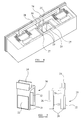
- Figure 4 shows a safety switch which includes all of the features illustrated in Figures 1 to 3, and which is provided with additional recesses 25 to receive an auxiliary contact switch.
- the additional recesses 25 are each dimensioned to receive a leg of an auxiliary contact switch.
- Electrical connectors 27, 28 pass from sides of the silicon block to auxiliary conducting plates 29, 30 located within the additional recesses 25.
- FIG. 5 shows a perspective view and a side view of an auxiliary contact switch generally indicated as 20.
- the auxiliary contact switch 20 comprises an n-shaped member with two legs 21, each leg 21 being provided with a conducting plate 22.
- a u-shaped portion 24 is provided on top of the n-shaped member 21.
- FIG. 6 shows the auxiliary contact switch 20 with its legs 21 located within the recesses.
- Each leg 21 is thinner than the additional recess 25 in which it is located, so that the auxiliary contact is moveable within the additional recesses 25.
- a ridge 26 is provided on the back of each leg 21 to restrict the range of movement of the auxiliary contact 21 so that it corresponds to the range of movement of the contact arm 14.
- the contact arm 14 is securely received in the U-shaped portion 24 of the auxiliary contact switch 20.
- the contact arm 14 pushes the auxiliary contact switch 20 back, such that the conducting plates 22 are held away from the auxiliary conducting plates 29, 30.
- the contact arm 14 is pushed forwards, and this pulls the auxiliary contact switch 20 forwards such that the conducting plates press against the auxiliary conducting plates 29, 30. In this way, the auxiliary contact circuits are formed.
- the auxiliary contact switch 20 may be used for example to activate a warning light which indicates that electromechanical machinery is operating, and/or other warning devices.
- the auxiliary contact switch may be modified so that it provides a warning if the safety switch is not operating correctly.
- the conducting plate 22 provided on each leg 21 of the auxiliary contact switch 20 may be split into a left hand plate and a right hand plate.
- the left hand plates may be connected together, and similarly the right hand plates may be connected together.
- the electrical 27, 28 may be connected to the conducting plates 29, 30 such that a closed circuit is formed by the left hand plates when the auxiliary contact switch 20 is pushed forwards, and similarly a closed circuit is formed by the right hand plates.
- one of the contact plates 14b of the contact arm 14 may become fused to a plate 7 of a fixed contact 6, such that the contact plate does not move away from the plate of the fixed contact when the coils 10 are turned off. This would cause the contact arm to skew (one end of the contact arm moving whilst the other end is fixed).
- the modified auxiliary contact switch 20 will indicate that the fusing has occurred, since it will be skewed along with the contact arm such that a closed circuit will be formed by the left hand plates of the auxiliary contact switch and an open circuit will be provided at the right hand plates (or vice-versa, depending upon where the fusing occurred). This is advantageous because it provides an immediate warning that one of the contact plates 14b has fused. It may be desired to make the auxiliary contact switch 20 wider, and move the left hand and right hand plates further apart, such that the effect of skewed movement is more pronounced and more likely to provide the combination of a closed circuit and an open circuit.
- a plurality of safety switches may be provided together as a single entity.
- four safety switches 1 are provided as a single unit.
- the coils 10 of each of the safety switches 1 may be connected to the same input, with the fixed contacts 6 each being connected to different outputs.
- a unit of this type may be used for example when more than one piece of electromechanical machinery is being powered, the pieces of electromechanical machinery all being located within the same enclosure.
- the door of the enclosure may be connected to the coils 10 of each of the safety switches 1, so that when the door of the enclosure is opened, the power supply to each piece of electromechanical machinery is interrupted via the fixed contacts 6.
- the term 'magnet' includes ferromagnetic substances that are not magnetised.
- the fixed magnets 4 may comprise steel or iron which is not magnetised, with the moveable magnets 12 being steel or iron which is magnetised (or vice versa).
- the illustrated embodiment of the invention includes two moveable magnets 12 which are connected by a contact arm 4, it will be appreciated that the invention may be implemented using only one moveable magnet, and without a contact arm.
- the contact arm may be replaced with a contact (the contact could for example be connected to a power supply for electromechanical machinery).
- the illustrated embodiment of the invention includes a contact plate 14b which is fixed to a moveable magnet, it will be appreciated that the moveable magnet itself may form a contact plate (the moveable magnet being electrically connected to for example a power supply circuit).
- the silicon block 2 may be 8x15mm with a depth of 1-2 mm.
- the illustrated embodiment of the invention includes coils fabricated by printing them onto, or etching them into, the silicon block 2.
- the coils may instead comprise conventional windings.
- the materials used to fabricate the embodiment of the invention may be replaced with other suitable materials.
- the block 2 may be formed from plastics instead of silicon.
Landscapes
- Physics & Mathematics (AREA)
- Electromagnetism (AREA)
- Engineering & Computer Science (AREA)
- General Engineering & Computer Science (AREA)
- Mechanical Engineering (AREA)
- Push-Button Switches (AREA)
Applications Claiming Priority (1)
| Application Number | Priority Date | Filing Date | Title |
|---|---|---|---|
| GBGB0514869.7A GB0514869D0 (en) | 2005-07-20 | 2005-07-20 | Safety switch |
Publications (2)
| Publication Number | Publication Date |
|---|---|
| EP1746615A2 true EP1746615A2 (de) | 2007-01-24 |
| EP1746615A3 EP1746615A3 (de) | 2008-03-26 |
Family
ID=34897503
Family Applications (1)
| Application Number | Title | Priority Date | Filing Date |
|---|---|---|---|
| EP06253762A Withdrawn EP1746615A3 (de) | 2005-07-20 | 2006-07-18 | Sicherheitsschalter |
Country Status (3)
| Country | Link |
|---|---|
| US (1) | US20070018766A1 (de) |
| EP (1) | EP1746615A3 (de) |
| GB (1) | GB0514869D0 (de) |
Families Citing this family (3)
| Publication number | Priority date | Publication date | Assignee | Title |
|---|---|---|---|---|
| USD567191S1 (en) * | 2006-02-14 | 2008-04-22 | Pilz Gmbh & Co. | Safety switching device |
| FR2926922B1 (fr) * | 2008-01-30 | 2010-02-19 | Schneider Electric Ind Sas | Dispositif de commande a double mode d'actionnement |
| US11657992B2 (en) | 2019-05-06 | 2023-05-23 | Jeffrey A. Stallmer | Protective cover assembly for magnetically actuating an electrical wall switch |
Family Cites Families (5)
| Publication number | Priority date | Publication date | Assignee | Title |
|---|---|---|---|---|
| BE568399A (de) * | ||||
| JP2613904B2 (ja) * | 1987-12-23 | 1997-05-28 | 松下電工株式会社 | 有極電磁石 |
| US4908588A (en) * | 1988-06-02 | 1990-03-13 | Hu Development Corporation | Matrix switch |
| IL91042A0 (en) * | 1989-01-25 | 1990-02-09 | H U Dev Corp | Solenoid actuator |
| US6661321B1 (en) * | 2002-08-30 | 2003-12-09 | Tendex Electric Co., Ltd. | Electromagnetic switch |
-
2005
- 2005-07-20 GB GBGB0514869.7A patent/GB0514869D0/en not_active Ceased
-
2006
- 2006-07-18 EP EP06253762A patent/EP1746615A3/de not_active Withdrawn
- 2006-07-19 US US11/489,092 patent/US20070018766A1/en not_active Abandoned
Also Published As
| Publication number | Publication date |
|---|---|
| EP1746615A3 (de) | 2008-03-26 |
| GB0514869D0 (en) | 2005-08-24 |
| US20070018766A1 (en) | 2007-01-25 |
Similar Documents
| Publication | Publication Date | Title |
|---|---|---|
| CN100543902C (zh) | 电磁继电器 | |
| KR101016212B1 (ko) | 마이크로 스위치 | |
| US3436497A (en) | Electrical switch having a lost motion operator assembly | |
| KR101879801B1 (ko) | 이중 브레이크 계전기 | |
| PL1843375T3 (pl) | Urządzenie uruchamiające elektromagnetyczne, zwłaszcza dla przełącznika napięcia średniego | |
| US9437375B2 (en) | Electromagnetic relay assembly having a switch control unit | |
| EP0844636A2 (de) | Elektromagnetisch betägigtes Schaltgerät | |
| KR101598421B1 (ko) | 전자접촉기 | |
| CA1146199A (en) | Electric control device with improved arc extinguishing means | |
| KR880001010A (ko) | 전기 단선 수단을 갖는 회로차단기 | |
| CN111613487A (zh) | 磁保持继电器及其工作方法 | |
| CN113272929B (zh) | 继电器 | |
| US20070018766A1 (en) | Safety switch | |
| US2918554A (en) | Interlock contact mechanism | |
| EP0165998B1 (de) | Lastschalter | |
| JP6764015B1 (ja) | 押しボタンスイッチ | |
| US3919675A (en) | Interlocking arrangement for a pair of electrical contactors | |
| KR20100038289A (ko) | 자기 작동식 전기 스위치 | |
| GB2160362A (en) | Electromagnetic device | |
| KR20170000324U (ko) | 조립 가이드가 구비된 직류 릴레이 | |
| JP6952125B2 (ja) | 永久磁石による消弧を改良したスイッチ装置 | |
| EP1310969B1 (de) | Schalter für Aussenrückblickspiegel | |
| KR19980024787A (ko) | 스위치, 특히 릴레이를 위한 구동 시스템 | |
| CN222562474U (zh) | 一种开关装置 | |
| JP2008034146A (ja) | 回路遮断器の電磁引き外し装置 |
Legal Events
| Date | Code | Title | Description |
|---|---|---|---|
| PUAI | Public reference made under article 153(3) epc to a published international application that has entered the european phase |
Free format text: ORIGINAL CODE: 0009012 |
|
| AK | Designated contracting states |
Kind code of ref document: A2 Designated state(s): AT BE BG CH CY CZ DE DK EE ES FI FR GB GR HU IE IS IT LI LT LU LV MC NL PL PT RO SE SI SK TR |
|
| AX | Request for extension of the european patent |
Extension state: AL BA HR MK YU |
|
| PUAL | Search report despatched |
Free format text: ORIGINAL CODE: 0009013 |
|
| AK | Designated contracting states |
Kind code of ref document: A3 Designated state(s): AT BE BG CH CY CZ DE DK EE ES FI FR GB GR HU IE IS IT LI LT LU LV MC NL PL PT RO SE SI SK TR |
|
| AX | Request for extension of the european patent |
Extension state: AL BA HR MK YU |
|
| RIC1 | Information provided on ipc code assigned before grant |
Ipc: H01H 51/01 20060101ALN20080219BHEP Ipc: H01H 50/54 20060101ALN20080219BHEP Ipc: H01H 50/20 20060101ALN20080219BHEP Ipc: H01H 50/04 20060101ALN20080219BHEP Ipc: H01H 51/20 20060101ALI20080219BHEP Ipc: H01H 51/22 20060101AFI20080219BHEP |
|
| 17P | Request for examination filed |
Effective date: 20080424 |
|
| 17Q | First examination report despatched |
Effective date: 20080715 |
|
| AKX | Designation fees paid |
Designated state(s): DE FR GB |
|
| RAP1 | Party data changed (applicant data changed or rights of an application transferred) |
Owner name: ROCKWELL AUTOMATION LIMITED |
|
| STAA | Information on the status of an ep patent application or granted ep patent |
Free format text: STATUS: THE APPLICATION IS DEEMED TO BE WITHDRAWN |
|
| 18D | Application deemed to be withdrawn |
Effective date: 20090127 |