EP1746846A1 - Bildverarbeitungseinrichtung mit farbverschiebungskorrekturfunktion, bildverarbeitungsprogramm und elektronische kamera - Google Patents
Bildverarbeitungseinrichtung mit farbverschiebungskorrekturfunktion, bildverarbeitungsprogramm und elektronische kamera Download PDFInfo
- Publication number
- EP1746846A1 EP1746846A1 EP05728731A EP05728731A EP1746846A1 EP 1746846 A1 EP1746846 A1 EP 1746846A1 EP 05728731 A EP05728731 A EP 05728731A EP 05728731 A EP05728731 A EP 05728731A EP 1746846 A1 EP1746846 A1 EP 1746846A1
- Authority
- EP
- European Patent Office
- Prior art keywords
- image
- color shift
- correction
- image processing
- processing device
- Prior art date
- Legal status (The legal status is an assumption and is not a legal conclusion. Google has not performed a legal analysis and makes no representation as to the accuracy of the status listed.)
- Granted
Links
Images




Classifications
-
- H—ELECTRICITY
- H04—ELECTRIC COMMUNICATION TECHNIQUE
- H04N—PICTORIAL COMMUNICATION, e.g. TELEVISION
- H04N25/00—Circuitry of solid-state image sensors [SSIS]; Control thereof
- H04N25/60—Noise processing, e.g. detecting, correcting, reducing or removing noise
- H04N25/61—Noise processing, e.g. detecting, correcting, reducing or removing noise the noise originating only from the lens unit, e.g. flare, shading, vignetting or "cos4"
- H04N25/611—Correction of chromatic aberration
Definitions
- the present invention relates to an image processing device, an image processing program, and an electronic camera.
- a conventional device disclosed in the patent document 1 detects a color shift in an edge part of an image first and corrects chromatic aberration of magnification by performing image processing based on the color shift. Further, a conventional device disclosed in the patent document 2 performs magnification adjustment for each color component of an image and corrects chromatic aberration of magnification by finding a point at which a difference between color components is minimum. Furthermore, the patent document 3 describes a technique for correcting a color shift that occurs at the time of motion image shooting etc, by locally detecting a color shift.
- Patent document 1 Japanese Unexamined Patent Application Publication No. 2000-299874
- Patent document 2 Japanese Unexamined Patent Application Publication No. 2002-344978 (Fig. 1, Fig. 3)
- Patent document 3 Japanese Patent No. 2528826
- An electronic camera incorporating an image pickup device of single-plate type has color filters of RGB etc. arranged on an image pickup plane and generates RAW data in one kind of color component is arranged on each pixel.
- the electronic camera generates image data having all colors on each pixel by generating missing color components of the RAW data through color interpolation processing.
- false color noises occur in image data.
- the electronic camera performs spatial frequency low-pass filtering to the chrominance component of the image data (hereinafter, this processing is referred to as "chrominance LPF").
- chrominance LPF spatial frequency low-pass filtering to the chrominance component of the image data
- a slight chrominance change occurs due to a color shift caused by chromatic aberration of magnification.
- the slight chrominance change will be a chrominance component of a high frequency area and removed by the above-described chrominance LPF.
- the color shift due to chromatic aberration of magnification is reduced by the chrominance LPF processing.
- a gradual chrominance change in the low frequency region occurs due to a color shift caused by the chromatic aberration of magnification.
- the chrominance change in the low frequency region is not removed by the above-described chrominance LPF and allowed to pass.
- the color shift due to chromatic aberration of magnification remains even after the chrominance LPF processing.
- the above-described patent documents 1 and 2 premise that the color shift due to chromatic aberration of magnification occurs in point symmetry with respect to the screen center (optical axis center).
- chrominance LPF causes unevenness in the chromatic aberration of magnification and the point symmetry is readily lost. Detection of the amount of aberration in such a state will cause errors in the detection result.
- the screen is brought into a state in which both of the color shifts due to chromatic aberration of magnification and the false color noises occur in a complex manner. In such a state, errors are likely to occur in the detection result of the amount of aberration. According to the patent documents 1 and 2, in particular, the color shift due to chromatic aberration of magnification is corrected uniformly in the screen, therefore, it is not possible to avoid the errors.
- the patent documents 1 and 2 are on the premise that the center of the screen of an image is the optical axis of the lens used at shooting, and the chromatic aberration of magnification occurs regularly around the optical axis. Therefore, when a lens used at the shooting is a shift lens or a lens with a hand movement correction function, the chromatic aberration of magnification cannot be corrected since the center thereof shifts from the screen center. Also, in a case where the image to be processed is an image after trimming, it cannot be corrected since the position of the image corresponding to the optical axis is uncertain. Note that, the above-described patent document 3 describes a local detection of a color shift.
- color shift detection is performed on a portion that needs no correction, therefore, the processing takes a lot of time. Further, the color shift detection is made similarly on all of the portions irrespective of the position and structure of a portion to be corrected, requiring extraneous processing time. Furthermore, the correction may not be performed properly.
- an object of the present invention is to provide a technique to optimally perform color shift correction to an image having a plurality of color component planes. Further, another object of the present invention is to provide a novel idea of monitoring erroneous correction of a color shift at the time of correcting the color shift of an image. Furthermore, still another object of the present invention is to provide a technique to correctly detect a color shift due to chromatic aberration of magnification, taking the influence of false colors etc. into account.
- An image processing device of the present invention performs image processing to an image represented by a plurality of color component planes and includes a correction unit and an erroneous correction detection unit.
- the correction unit corrects a color shift in the image.
- the erroneous correction detection unit judges that the correction unit has made an erroneous correction by comparing the images before and after the correction by the correction unit.
- the erroneous correction detection unit judge an erroneous correction when a chrominance of a portion to be processed of the image after the correction is not within an allowable range which is set using the image before the correction as a reference.
- the erroneous correction detection unit suppress the erroneous correction by limiting the chrominance of the image after the correction within the allowable range.
- the erroneous correction detection unit calculate minimum and maximum values of a group of chrominances including chrominances of the image before the correction within a local region and predetermined chrominances representing low chroma, to determine a range of the minimum and maximum values to be said allowable range.
- the local region includes the portion to be processed.
- the correction unit suppress the error correction by reducing a shift amount of the color shift correction when the erroneous correction detection unit judges the erroneous correction.
- the above-mentioned color shift be a color shift occurring in the image due to the chromatic aberration of magnification of an optical system, and that the correction unit adjust (resize) magnification of the color component planes in such a direction as to negate the chromatic aberration of magnification.
- another image processing device of the present invention estimates a chromatic aberration of magnification of an optical imaging system from an input image and includes a color shift detection part and an estimation part.
- the color shift detection part detects an amount of the color shift in a radius direction at a plurality of portions of the image.
- the estimation part calculates a statistical distribution of the chromatic aberration of magnification based on the color shift amount of the plurality of portions, and calculates a value which is greater than an average value of the statistical distribution and falls within a range of the statistical distribution, to set the calculated value as an estimation value of the chromatic aberration of magnification.
- the estimation part include a normalization part and a coefficient processing part.
- the normalization part divides the color shift amount by an image height (radius) of the portions and calculates a magnification difference in the color components indicated by the color shift.
- the coefficient processing part calculates a histogram distribution of magnification differences calculated at each of the portions, selects, from the histogram distribution which is an asymmetric curve, such a value that it is on a biased side of the curve and that it falls within a range of the distribution of the biased side, and determines the value as an estimation value of the chromatic aberration of magnification.
- the estimation part calculate an estimation value of the chromatic aberration of magnification for each divided region of the image.
- the estimation part detect the color shift in the radius direction for each divided region of the image and vector-synthesize the color shifts between neighboring divided regions, to thereby detect even an asymmetric chromatic aberration of magnification relative to a center of the screen.
- another image processing device of the present invention performs image processing to an image represented by a plurality of color component planes and includes an edge region detection unit, a direction detection unit, and a color shift detection unit.
- the edge region detecting unit detects edge regions of the image.
- the direction detection unit detects a gradient direction of luminance of an edge of each of the edge regions.
- the color shift detection unit detects, in the gradient direction of the luminance, the color shift in an image of each of the edge regions between an image signal of an arbitrary color component plane and an image signal of another color component plane different from the arbitrary color component plane.
- another image processing device of the present invention performs image processing to the image represented by a plurality of color component planes and includes an edge region detection unit and a color shift detection unit.
- the edge region detecting unit detects edge regions of an image.
- the color shift detection unit detects the color shift in an image of each of the edge regions between an image signal of an arbitrary color component plane and an image signal of another color component plane different from the arbitrary color component plane in a radius direction around a part corresponding to an optical axis of an optical system used for generation of the image.
- the image processing device prefferably includes a correction unit which corrects the color shift in each of the edge regions detected by the color shift detection unit.
- the image processing device prefferably includes a chroma judgment unit which detects a chroma of the image in each of the edge regions and judges whether or not the chroma is higher than a predetermined value.
- the color shift detection unit detects the color shift.
- the color shift detection unit include, for each edge region, a window with a size which is determined according to a width of the edge of each of the edge regions, and detect the color shift in an image in the window.
- the color shift detection unit detect the color shift in the image in the window by finding a correlation between an image signal of an arbitrary color component plane and an image signal of another color component plane different from the arbitrary color component plane.
- the image processing device prefferably includes an evaluation unit which reviews the color shift detected by the color shift detection unit based on a result of the color shift at the plurality of portions.
- the correction unit corrects the color shift based on a result of the review by the evaluation unit.
- the correction unit correct the color shift after performing smoothing processing to the color shift detected by the color shift detection unit.
- the above-described correction unit smooth the chrominance in each of the edge regions after correcting the color shift.
- An image processing program of the present invention causes a computer to function as the image processing device according to any one of the above-mentioned items [1] to [19].
- An electronic camera of the present invention includes the image processing device according to any one of the above-mentioned items [1] to [19] and an image pickup part that shoots an object image to generate an image.
- the image generated by the image pickup part is processed by the image processing device.
- the image processing device in the above-mentioned item [1] not only detects and corrects a color shift but also makes a comparison between the images before and after the correction in accordance with the correction of the color shift. It judges the erroneous correction of the color shift from the comparison result. In this way, monitoring the occurrence of the erroneous correction of the color shift makes it possible to issue a warning of and ex post facto deal with the problem, which is otherwise impossible by only performing the color shift correction.
- the erroneous correction it is possible to deal with the erroneous correction by restoring the color shift correction only at an erroneously corrected portion. Further, for example, when the number of erroneously corrected portions exceeds a predetermined number (a predetermined size), it is possible to deal with the erroneous correction by performing a modified color shift correction again using the result as a reference.
- a predetermined number a predetermined size
- the image processing device in the above-mentioned item [2] detects the erroneous correction in accordance with a change of the chrominance before and after the color shift correction.
- a color shift is corrected correctly, anomalous chrominance at the portion including the color shift varies toward normal chrominance.
- the chrominance at the portion including the color shift changes in a reverse manner in many cases. Accordingly, monitoring the chrominance change before and after the color shift correction makes it possible to judge the erroneous correction more correctly.
- the image processing device in the above-mentioned item [7] precisely calculates the chromatic aberration of magnification from the statistical distribution of the chromatic aberration of magnification on the screen.
- An image having been subjected to false color reduction processing or the like includes both of portions with reduced chromatic aberration of magnification and portions with chromatic aberration of magnification not reduced.
- An average value of the statistical distribution of chromatic aberration of magnification for such an image will be a rather smaller value than an actual chromatic aberration of magnification in terms of absolute value. In this case, it is unlikely that the actual chromatic aberration of magnification exceeds the range of the statistical distribution.
- this image processing device finds a value that is greater than the average value and falls within the range of the statistical distribution from the statistical distribution of chromatic aberration of magnification and set the value as an estimation value of the chromatic aberration of magnification.
- the image processing device in the above-mentioned item [11] detects edge regions from an image and detects a gradient direction of a luminance of the edge. It detects the color shift in the edge regions in the gradient direction of the luminance. Generally, a color shift occurring in the edge region is conspicuous. In particular, a color shift occurring in the gradient direction of the edge region is more conspicuous. On the other hand, a smooth color shift is visually inconspicuous, even when amounts of the color shift are the same. Therefore, as this image processing device does, detecting the color shift in the edge regions (particularly, in the gradient direction) makes it possible to selectively detect the visually conspicuous color shift.
- This also makes it possible to preferentially detect a color shift in a region with a high spatial frequency which is a more conspicuous region, in a case where an image has an uneven color shift in-between a portion with a high spatial frequency and a portion with a low spatial frequency due to false color reduction processing. This realizes a color shift detection more suitable for suppression of a conspicuous color shift.
- the image processing device detects edge regions of an image and detects a color shift in the edge regions in a radius direction around a part corresponding to the optical axis of the optical system used for generation of the image.
- the color shift in chromatic aberration of magnification occurs in the radius direction relative to the center of the optical axis of the optical imaging system.
- other false colors etc. occur irrespective of the radius direction. Therefore, detecting a color shift only in the radius direction makes it possible to suppress erroneous detection of the color shift due to the false colors etc. As a result, it is made possible to preferentially detect the color shift in the image due to the chromatic aberration of magnification.
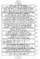
- Fig. 1 is a flow chart for explaining the computer operation by an image processing program. It is possible to cause the computer to function as an image processing device by the image processing program. The operation in a first embodiment is explained below along the step numbers shown in Fig. 1.
- a computer captures image data (hereinafter, referred to as an input image) shot by an electronic camera via a recording medium or a communication interface.
- the input image has already been subjected to color interpolation and chrominance LPF in the electronic camera.
- the computer sets an optical axis center of an optical imaging system in the screen of the input image.
- the screen center of the input image is set as an optical axis center by default.
- the computer may also be possible for the computer to acquire the position of the optical axis center from attached information (Exif information etc.) of the input image.
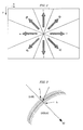
- the computer divides the input image in the circumference direction around the optical axis and sets a plurality of divided regions and the radius direction of each divided region.
- Fig. 2 shows an example of the setting of the divided region and the radius direction.
- the input image is divided into eight divided regions N, NE, E, SE, S, SW, W, and NW and the arrow shown for each divided region is set as its radius direction.
- the computer calculates the level change of the luminance Y in the radius direction in the screen area (a region etc. 50% or more of the maximum image height distant from the optical axis center) in which the chromatic aberration of magnification can be recognized visually.
- the radius direction for each divided region it is made possible to perform simple calculation based on the following expressions.
- the computer calculates a start point a at which a change from dark to light or vice versa begins and an end point b at which the change ends.
- the computer stores a middle point c between a and b as a portion with a level change and stores the distance between a and b as the thickness of the edge.
- the detection of the portion with a level change may be performed discretely on the screen with predetermined sampling intervals.
- the computer sets a local window around the portion with a level change and acquires the G array of the window. Further, the computer acquires the R array from the position to which the window is displaced in the radius direction. Next, after adjusting each signal level of the R array so that the average value of the G array is equal to that of the R array, the computer calculates a difference between elements in the G array and the R array and calculates an overlap error by cumulatively summing up the absolute value of the difference. The computer searches for such a displacement amount as to reduce the overlap error to minimum (or locally minimum) while changing the displacement amount of the R array with respect to the G array and stores the displacement amount as the color shift amount between the RG components.
- the color shift amount with precision equal to or less than the distance between pixels by interpolating the value of the overlap error.
- the computer calculates the magnification difference between the R plane and the G plane by dividing the color shift amount calculated for each portion with a level change by the image height (the radius from the optical axis center) of the portion with a level change, respectively.
- the computer sums the frequency of the magnification difference calculated for each portion with a level change and creates a histogram distribution.
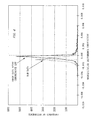
- Fig. 4 shows an example of the histogram distribution.
- the solid line shown in Fig. 4 indicates the histogram distribution of the input image after the above-described chrominance LPF.
- the most frequent value in this case is approximately zero. This means that most of the chromatic aberration of magnification has been reduced by the chrominance LPF.
- the curves that start from the most frequent value are asymmetric and biased to the negative side in Fig. 4.
- the biased curve shows a remaining chromatic aberration of magnification.
- the true magnification difference of the optical imaging system is on the biased side.
- the dotted line shown in Fig. 4 indicates a histogram distribution of magnification differences, which is created for an experimental purpose, of the RAW data (data before the color interpolation and before the chrominance LPF).
- the RAW data is not affected by the reducing action of the chromatic aberration of magnification by the chrominance LPF, so that the curve may be substantially symmetric with respect to the most frequent value, that is, substantially a normal distribution. In this case, it is possible to regard that the value of the most frequent value indicates the magnification difference of the optical imaging system to be calculated.
- the computer calculates the following expression using the magnification difference coefficient k of the R plane and calculates the color shift in the corresponding R plane for each pixel (x, y) of the G plane as a displacement vector (dx, dy).
- dx - k ⁇ x - xo
- dy - k ⁇ y - yo
- (xo, yo) is the optical axis center.
- the computer calculates a position (x - dx, y - dy) of the R pixel displaced by the chromatic aberration of magnification from the pixel (x, y) of the G plane and the displacement vector (dx, dy) and set it to a reference position.
- the computer selects a low chroma chrominance (here, chrominance is zero) as a third candidate of the above-described allowable range.
- the low chroma chrominance will limit the chrominance after the correction to a low chroma because it is highly possible that a chrominance having the opposite sign of those of the chrominances Cr and Cr' occurs. Therefore, the chroma chrominance is not limited to the chrominance zero but can be any chrominance indicating a low chroma.
- the computer determines the upper limit and the lower limit of the allowable range for each G pixel using the three candidates as follows.
- the computer calculates a provisional chrominance (R' - G) that appears after the color shift correction from the pixel value R' of the reference position (x - dx, y - dy) and the pixel value G of the pixel (x, y).
- the computer limits the chrominance (R' - G) by the upper chrominance limit and the lower chrominance limit determined in step S10. At this time, the portion at which the chrominance goes out from the allowable range will be the detection portion of the color shift erroneous correction.
- the pixel value R' is regarded as an R component Rout after the correction. If lower chrominance limit > chrominance (R' - G), the pixel value of the lower limit (G + lower chrominance limit) is regarded as the R component Rout. If upper chrominance limit ⁇ chrominance (R' - G), the pixel value of the upper limit (G + upper chrominance limit) is regarded as the R component Rout.
- the computer corrects the chromatic aberration of magnification and thus the R plane on which the color shift in the opposite direction is suppressed is completed. It may also be possible to simultaneously judge and suppress the above-mentioned erroneous correction by an operation to limit the R' value by the amount displaced by the lower chrominance limit and the upper chrominance limit from the G value as a reference. Further, as another method different from the above, when the chrominance (R' - G) is not within the allowable range, it may also be possible to perform the correction again after reducing the correction amount of the color shift at the portion. When portions not within the allowable range appear in the number equal to or greater than a fixed amount (a fixed area), it may also be possible to perform the color shift correction of the whole R plane again after reducing the value of the magnification difference.
- the computer performs the same processing to the B component of the input image and calculates the B component Bout after the correction for each pixel (x, y).
- the computer outputs an output image the color components of which are the original G component of the input image, the R component Rout calculated by the color shift correction, and the B component Bout calculated by the same color shift correction.
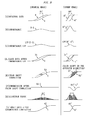
- Fig 5 is a diagram for explaining the function and effect of the present embodiment.
- Fig. 5[A] shows a gradual edge (R, G) and a steep edge (R", G").
- Fig. 5[B] shows the chrominances of both the edges, respectively.
- a chrominance change (R - G) in the low frequency area appears at the gradual edge.
- a chrominance change (R" - G”) in the high frequency area appears due to the color shift ⁇ C.
- Fig. 5[C] shows the result of the performance of the chrominance LPF for both the chrominance changes.
- the chrominance change in the low frequency area is maintained and allowed to pass.
- the chrominance change in the high frequency area is suppressed by the chrominance LPF.
- Fig. 5[D] shows the RG components (R1 and G in the figure) after the chrominance LPF.
- the R components R and R1 before and after the chrominance LPF do not change quite and the color shift ⁇ C due to the chromatic aberration of magnification remains as it is.
- the chrominance change in the high frequency area is suppressed by the chrominance LPF, therefore, the phase difference in the RG components (R1" and G" in the figure) after the chrominance LPF becomes small. As a result, the color shift due to the chromatic aberration of magnification is improved.
- the chromatic aberration of magnification remains in the portion with a low spatial frequency but it is reduced in the portion with a high spatial frequency.
- the chromatic aberration of magnification occurs unevenly in the screen.
- the solid line histogram shown in Fig. 4 will not simply be a normal distribution and an asymmetric bias occurs in the variations in the histogram.
- step S6 of the present embodiment attention is paid on the asymmetric bias to estimate the variation distribution of the magnification difference, which should be symmetric originally, and the true magnification difference (magnification difference coefficient) has been successfully determined from the estimation result.
- Fig. 5[E] shows a state in which the color shift ⁇ C of the R component has been returned to the original pixel position using the magnification difference coefficient thus determined.
- the color shift correction acts excessively, resulting in the displacement as far as R2" in the figure, and a color shift in the opposite direction occurs.
- Fig. 5[F] shows chrominances (R2 - G) and (R2" - G") after the color shift correction.
- the chrominance (R2 - G) does not change so much before and after the color shift correction.
- the chrominance (R2" - G) changes considerably before and after the color shift correction.
- Fig. 5[G] shows a thus determined allowable range (a region with vertical lines in the figures).
- the chrominance change before and after the color shift correction is small and substantially falls within this allowable range, therefore, limitation of the color shift correction is not imposed positively.
- the chrominance change before and after the color shift correction is large and the chrominance change is limited positively in the allowable range.
- Fig. 5[H] shows image data after the color shift correction when chrominance limitation is imposed.
- R2 and G shown in the figure almost no chrominance limitation is imposed and the favorable color shift correction is maintained as it is.
- R3" and G" shown in the figure chrominance limitation is imposed, therefore, the color shift correction is weakened. As a result, the color shift in the opposite direction is suppressed.
- the chrominance limitation explained here is effective not only for an image having been subjected to the chrominance LPF processing but also for suppressing the erroneous correction (in particular, excessive correction) when a color shift in a general image is corrected.
- Fig. 6 is a diagram for explaining the reason that the upper limit and the lower limit of the chrominance are set to max (0, Cr, Cr') and min (0, Cr, Cr'), respectively.
- Fig. 6[A] shows an example where the image structure becomes extinct when the upper chrominance limit of the allowable range is temporarily set to max (0, Cr).
- the G component does not change but the R component R1 varies considerably locally.
- the chrominance becomes large at the peak portion of the R component R1. If correction is made such that the R component R1 is shifted in the rightward direction in the figure as shown in Fig. 6[B], a new peak appears in the chrominance after the correction.
- the chrominance after the correction has a large peak because of the structure of the image and not because of false colors or secondary color shifts.
- the upper chrominance limit is temporarily set to max (0, Cr)
- the allowable range will be a diagonally shaded region shown in Fig. 6[C] and the chrominance after the correction becomes extinct as the RG components shown in Fig. 6[D].
- the allowable range will be the diagonally shaded range in Fig. 6[E] or Fig. 6[F].
- the chrominance peak after the correction is maintained and the image structure is kept correctly as R2 and G shown in Fig. 6[G].
- Fig. 6[H] shows an example where the image structure is destroyed when the lower chrominance limit of the allowable range is set to min (0, Cr).
- Fig. 6[I] shows an example where the image structure is destroyed when the upper chrominance limit of the allowable range is set to max (0, Cr').
- Fig. 6[J] shows an example where the image structure is destroyed when the lower chrominance limit of the allowable range is set to min (0, Cr').
- Fig. 7 and Fig. 8 are diagrams for explaining the second embodiment.
- the optical axis center of an optical imaging system is located substantially at the screen center of image data. Because of this, usually, the chromatic aberration of magnification is produced in a point symmetric manner with respect to the screen center.
- the optical axis center of the optical imaging system does not necessarily coincide with the screen center of image data. Further, a case is supposed where the optical axis center of an optical imaging system comes not to coincide with the screen center of image data any longer after the image data is subjected to trimming (cropping) by processing on an electronic camera or a computer.
- the second embodiment discloses effective color shift correction even in the case where the optical axis center shifts from the screen center as described above. The operation of the second embodiment is explained below.
- a computer executes the operations in the above-described steps S2 to S4 or steps S21 to S24 and calculates the magnification difference in color shift for each of the eight divided regions N, NE, E, SE, S, SW, W, and NW.
- the computer combines three divided regions each to classify them into an upper side group (NW, N, NE), a right side group (NE, E, SE), a lower side group (SE, S, SW), and a left side group (SW, W, NW).
- the computer performs a histogram analysis of the magnification difference and calculates four magnification difference coefficients Kn, Ke, Ks, and Kw, respectively, for each of the four groups.
- the computer divides the screen into upper-right, lower-right, lower-left, and upper-left sections.
- the computer calculates a displacement vector (dx, dy) of the color shift by combining the magnification difference coefficients in the neighboring groups and vector-synthesizing them in accordance with the following expressions.
- the magnification difference coefficients in the plural directions are vector-synthesized.
- the crossing point of the displacement vectors in the above expressions that is, the optical axis center
- the optical axis center shifts from the screen center (xo, yo). Therefore, it is made possible to flexibly deal with the case where the optical axis center shifts from the screen center (xo, yo) by the above-mentioned calculation and further, it is made possible to calculate a more proper general-purpose displacement vector.
- the operation after the displacement vector (dx, dy) is calculated is the same as that in the first embodiment, therefore, its explanation is omitted here.
- the third embodiment describes a computer equipped with the image processing function of the present invention.
- a computer 10 includes a control part 1, an external interface part 2, and an operation part 3.
- the control part 1 records in advance a program for performing the image processing of the present invention.
- the external interface part 2 interfaces with an external device such as an electronic camera via a predetermined cable or a radio channel.
- the operation part 3 is equipped with a keyboard, a mouse, etc., although not shown.
- the external interface part 2 In the computer 10 having a configuration as shown in Fig. 9, it is possible for the external interface part 2 to capture an image from an external device such as an electronic camera, not shown, in accordance with the direction of the control part 1.
- the operation part 3 accepts various user operations.
- the state of the operation part 3 is detected by the control part 1.
- Fig. 10 shows a rough flow of color shift correction. Explanation is given below following the step numbers.
- the computer 10 reads an image from an external device such as an electronic camera, not shown, via the external interface part 2. It may also be possible to design so that an image recorded in a recording part, not shown, in the computer 10 is read (read out).
- the image to be read is an image to be processed, having respective color component planes of R, G, and B.
- the number of pixels in the x axis direction of the image to be read is Nx
- the number of pixels in the y axis direction is Ny
- the origin is any one of four corners of the image.
- the control part 1 detects an edge.
- the eight directions are those shown by a to h in Fig. 11.
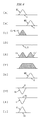
- the differentiation of the luminance is performed respectively by using the filters shown in a to h in Fig. 12. Then, if any of the differentials of the luminance in the eight directions is greater than a predetermined value (for example, about 10 in 256 gradations), the portion is regarded as an edge.
- a predetermined value for example, about 10 in 256 gradations
- the control part 1 performs the above processing for the whole image and detects an edge. Then, color shift direction detection portions are provided at intervals of several pixels in the vicinity of the detected edge and the direction in which the differential of the luminance is greatest among the eight directions in which the differentials are calculated at the portions as described above is determined as the gradation direction of the luminance of the edge. Then, this gradient direction of the luminance of the edge is regarded as the color shift detection direction, which will be described later.
- Fig. 13(a) is a general view of the image to be processed and Fig. 13(b) is a partially enlarged diagram.
- a pixel A in Fig. 13 shows an example of the above-described color shift detection portion.
- Fig. 13 shows an example in which the gradient direction of the luminance is the direction of the arrow d in Fig. 11.
- the diagonally shaded part in Fig. 13 shows the object region.
- the differential of the pixel A and the pixel adjacent to the pixel A along the arrow d is calculated.
- the differential between the pixel and the further neighboring pixel is calculated and when a pixel P (p) is not an edge and the next pixel P (p+1) is an edge, the pixel P (p) is determined as a pixel B (refer to Fig. 13).
- the same processing is performed in the opposite direction and when a pixel P (q) is an edge and the next pixel P (q+1) is not an edge, the pixel P (q) is determined as a pixel C (refer to Fig. 13).
- the pixel B and the pixel C thus calculated correspond to the pixels substantially at the edge end as shown in Fig. 13. Then, the control part 1 determines the distance between the pixel B and the pixel C as the width of the edge. Based on the width of the edge, the size of a window, which will be described later, is determined. Specifically, the size of the window is set to about four times the width of the edge.
- the pixel A is determined as an object of the color shift detection, and the region between the pixel B and the pixel C is determined as a region which needs a color shift correction.
- the absolute value of the chrominance of the pixels B and C corresponds to the predetermined value in the above-mentioned item [14].
- Such processing allows the chroma of the edge part to be obtained and makes it possible to perform the color shift detection and correction only on a part of the edge of the image at which the chromatic aberration of magnification has occurred.
- the computer 10 detects the color shift in the image of the R component to the image of the G component.
- the computer similarly detects the color shift in the image of the B component to the image of the G component.
- the image of the G component corresponds to the "image signal of an arbitrary color component plane among the plurality of color component planes"
- the image of the R component corresponds to the "image signal of another color component plane different from the arbitrary color component plane”.
- the control part 1 performs the detection of the color shift in the image of the R component to the image of the G component for each color shift detection portion determined in step S 102.
- the control part 1 is provided with a window around the color shift detection portion.
- the window is a square region and the length of its side is made to have about four times the width of the edge calculated in step S102.
- an image of the window is extracted from the image of the G component among the images to be processed.
- the image of the window extracted from the image of the G component is referred to as a "G component window".
- the image of the R component is extracted from the position shifted by an amount (dx, dy) from the G component window in the x direction and the y direction.
- the image of the R component to be extracted is the image at the position shifted from the G component window by the amount of shift (dx, dy) and hereinafter referred to as an "R component window".
- the above processing is repeated while the amount of shift (dx, dy) is slightly changed.
- the amount of shift when the overlap error of R and G is minimum (or local minimum) is determined as a color shift detection value and a chromatic aberration of magnification detection value d min is determined based on the color shift detection value.
- control part 1 performs the processing explained above for each color shift detection portion detected in step S102.
- the computer 10 corrects the color shift in the image of the R component (B component) to the image of the G component.
- the control part 1 corrects the color shift in the image of the R component relative to the image of the G component for each edge region.
- the control part 1 reads the chromatic aberration of magnification detection value d min calculated in advance for the edge region and moves the image of the R component with respect to the image of the G component by an amount of shift indicated by the chromatic aberration of magnification detection value d min in the direction opposite to the color shift direction indicated by the chromatic aberration of magnification detection value d min .
- the computer 10 superposes the image of the G component (the original image of the G component), the image of the R component and the image of the B component after the correction among the images read in step S101 and records it in a recording part, not shown, of the computer 10.
- the control part 1 superposes the image of the G component (the original image of the G component), the image of the R component corrected in step S104, and the image of the B component corrected in step S106 among the images read in step S101 and records it in a recording part, not shown, in the computer 10.
- correction is performed by moving, among the images of the respective color components of R, G, and B, with respect to the image of the G component that is the image of the color component in charge of the luminance, the image of the R component (or the image of the B component), which is the image of the other color component. Therefore, it is possible to perform the correction of the chromatic aberration of magnification while keeping the image quality (the feeling of sharpness) without degradation of the high frequency components.
- control part 1 may also be possible to evaluate the detected color shift after the color shift is detected and perform the correction of the chromatic aberration of magnification based on the result of the evaluation. It may also be possible for the control part 1 to, after calculating the chromatic aberration of magnification detection value d min for each edge region, when the chromatic aberration of magnification detection value d min in an image in the edge region is quite different from the chromatic aberration of magnification detection value d min in the peripheral color shift detection portion, invalidate the chromatic aberration of magnification detection value d min and perform the correction by substituting the chromatic aberration of magnification detection value d min of a proximate image therefor.
- chromatic aberration detection value d min it may also be possible to notify a user that the chromatic aberration of magnification detection value d min is not proper.
- the correction is performed only to a specific part of an image, it is possible to prevent the image after the correction from deteriorating, which is caused because the amount of correction is not continuous, by performing low pass filer processing using, for example, a 3 ⁇ 3 average filter. It is also recommended to detect the erroneous correction by comparing the image before the correction with the image after the correction.
- the control part 1 calculates a difference in the signal value between the image of the G component and the image of the R component before the correction when, for example, having performed the correction of the color shift in the image of the R component to the image of the G component and further, calculates a difference in the signal value between the image of the G component and the image of the R component after the correction, and compares the two differences.
- the control part 1 regards that the correction has been performed correctly.
- the control part 1 regards that the erroneous correction has been performed. Then, the control part 1 reduces the magnitude of the correction less than the correction based on the sought chromatic aberration of magnification detection value d min and performs the correction of the color shift again.
- the image may be brought back into a state in which it is in before the correction or the detection of the color shift may be restarted. As described above by detecting the erroneous correction, it is possible to automatically perform a more proper correction.
- the edge region is detected among the images represented by the plurality of color component (the respective color components of R, G, and B) planes.
- the gradient direction of the luminance of the edge is detected for each edge region.
- the color shift in the image between the image signal of an arbitrary color component plane in each of the edge regions and the image signal of another color component plane different from the arbitrary color component plane is detected in the gradient direction, thereby correcting the detected color shift in each region.
- unevenness occurs in the amount of color shift in the image after the color interpolation and the amount of shift differs from edge region to edge region.
- the edge region from the image and detecting and performing the correction of the color shift for each edge region, it is possible to properly deal also with the unevenness in the color shift such as that after the color interpolation.
- the chromatic aberration of magnification is unlikely to occur on a flat part but is likely to occur at an edge part. Therefore, by detecting an edge region and detecting a color shift in the edge region, it is possible to reduce the processing time taken for the detection and correction of the color shift while detecting with efficiency.
- the chromatic aberration of magnification is conspicuous when occurring in the gradient direction of the luminance. Therefore, by detecting the gradient direction of the luminance and detecting the color shift in the direction, it is possible to reduce the processing time taken for the detection and correction of the color shift without degrading precision in detection. Furthermore, with this method, it is possible to calculate the chromatic aberration of magnification detection value d min even when the image to be processed is a trimmed image.
- the chroma of the image of each of the edge region is detected to judge whether or not the chroma is higher than the predetermined value.
- the color shift is detected. Because of this, only a part of the edge of the image in which the chromatic aberration of magnification has occurred is the object of the detection and color shift correction, improving efficiency of the processing. Furthermore, the edge of the region in which the chroma of the subject is high is not the object of the correction, thereby decreasing degradation of the image due to the erroneous detection of the color shift.
- the size of the edge region is changed according to the width of the edge.
- an edge region can be small in size.
- the size of the edge region to detect the color shift needs to be large to some extent. Therefore, with the narrow width of the edge, the size of the edge region is reduced, and with the wide width of the edge, the size of the edge region is increased. Changing the size of the edge region as described above can realize efficient detection of the color shift.
- the fourth embodiment is explained below.
- the present embodiment as the third embodiment, describes the computer 10 equipped with the function of image processing performed by the image processing device of the present invention.
- the fourth embodiment is more simplified than the third embodiment.
- the rough flow of the correction of the color shift is the same as that in the third embodiment (refer to Fig. 10).
- Step 102 which is different from that in the third embodiment, is explained below.
- step S102 after detecting an edge region, the control part 1 performs the following processing instead of detecting the gradient direction of the luminance.
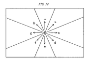
- the control part 1 divides an image to be processed into eight regions with the center of the image being its center as shown in Fig. 14.
- the direction representative of the region (arrows a to h) is considered as the direction of the color shift detection.
- the chromatic aberration of magnification frequently occurs in the radius direction (directions of the arrows a to h in Fig. 14) around the part (corresponding to the center of the image to be processed) corresponding to the optical axis of the optical system used when the image is generated. Therefore, by performing the detection of the color shift by shifting in the radius direction, it is possible to reduce the processing time taken for the detection of the color shift without degrading the precision in detection.
- Fig. 15(a) is a general view of an image to be processed and Fig. 15(b) is a partially enlarged diagram.
- Fig. 15 shows an example in which the differential of the luminance in the direction of the arrow d in Fig. 11 (the edge region is in the region d in Fig. 14) is calculated.
- the diagonally shaded part in Fig. 15 shows the region of the object.
- Fig. 15 when the differential of the luminance is calculated in the direction of the arrow d, the differential of two pixels adjacent to each other along the arrow d is calculated.
- the pixel P (p) When a pixel P (p) is not an edge and the next pixel P (p+1) is an edge, the pixel P (p) is determined as a pixel A (refer to Fig. 15). With further differentiation, when a pixel P (q) is an edge and the next pixel P (q+1) is not an edge, the pixel P (q) is determined as a pixel B (refer to Fig. 15). Finally the pixel corresponding to the middle point of the pixel A and the pixel B is determined as a pixel C (refer to Fig. 15). Among the pixels A to C thus calculated, the pixel A and the pixel B indicate the pixel substantially at the edge end and the pixel C indicates the pixel substantially at the edge boundary, as shown in Fig. 15.
- the distance between the pixel A and the pixel B is determined as the width of the edge.
- the size of the edge region is determined. Specifically, the size of the edge region is set to about four times the width of the edge.
- the edge region is detected among the images represented by the plurality of color component (the respective color components of R, G, and B) planes, and for each edge region, the color shift between the image signal of an arbitrary color component plane in the image in the edge region and the image signal of another color component plane different from the arbitrary color component plane is detected in the radius direction around the part corresponding to the optical axis in the optical system used when the image is generated, and the detection is performed for each region for which the detected color shift is corrected. Therefore, it is possible to reduce the processing time taken for the detection and correction of the color shift without degrading the precision in detection.
- the fifth embodiment is explained below.
- the present embodiment as the third embodiment and the fourth embodiment describes a computer equipped with the function of the image processing performed by the image processing device of the present invention.
- color bleeding is corrected in addition to the chromatic aberration of magnification explained in the third and the fourth embodiments.
- the chromatic aberration of magnification will also cause color bleeding.
- the wavelength of light that an R image pickup device corresponding to an R color filter receives has a range and the R image pickup device receives light of both of different wavelengths ⁇ 1 and ⁇ 2. Therefore, with a shooting lens having the chromatic aberration of magnification, light with ⁇ 1 and light with ⁇ 2 emitted from the same point of an object form an image at different positions, causing a blur in the image of the R component and color bleeding.
- the color bleeding is corrected.
- Fig. 16 is a flow chart for explaining the correction operation.
- the processing is the same as that in steps S101 to 104 in the third embodiment.
- the control part 1 calculates a difference in the signal value between the image of the G component and the image of the R component before the correction and further calculates a difference in the signal value between the image of the G component and the image of the R component after the correction, and compares the two differences.
- the control part 1 regards that the correction has been performed correctly.
- the control part 1 regards that the erroneous correction has been performed.
- the control part 1 reduces the magnitude of the correction less than the correction based on the sought chromatic aberration of magnification detection value d min and performs the correction of the color shift again.
- the control part 1 reduces the magnitude of the correction less than the correction based on the sought chromatic aberration of magnification detection value d min and performs the correction of the color shift again.
- it may also be possible to perform the re-correction of the color shift to the original image or perform the re-correction in the opposite direction to the image to which the correction of the color shift has been performed once.
- the control part 1 calculates the chrominance Cr of the R component for the whole image to be processed.
- Cr is given, for example, as (R - G).
- the edge region of the image of Cr calculated in the above is subjected to low pass filter.
- the low pass filter replaces the chrominance Cr at a certain portion with a weighted average value of a square region with the portion being its center.
- the area of the square region is determined in accordance with the chromatic aberration of magnification detection value d min calculated in step S113. Specifically, the length of a side of the above-mentioned square region is set to twice to four times the color shift detection value (units: pixel).
- the above processing is performed to the whole image.
- the chrominance of R after the processing is assumed to be Cr'
- the R component after the correction is given as (Cr' + G).
- the same processing is performed to the B component.
- the processing is the same as that in step S105 in the third embodiment.
- the chrominance is smoothed for each edge region after the correction of the color shift is performed.
- the degree of color bleeding becomes greater when the chromatic aberration of magnification occurs in the greater magnitude, therefore, by performing such processing, it is made possible to remove the color bleeding in addition to the chromatic aberration of magnification and the quality of the image can be improved.
- the embodiment above has described the example in which the object to be processed includes the color components of RGB, however, a color coordination system such as one consisting of cyan, magenta, yellow, etc. may be used. It may also be possible to generate an image in another color coordination system based on the image to be processed and perform the same detection and correction on the assumption that the image is to be processed.
- the embodiment above has described the image processing device that detects and corrects a color shift, however, only the detection of the color shift may be performed. Then, the image processing device that detects such a color shift can be used in the verifying process etc. in the manufacturing process of lenses.
- Fig. 17 is a block diagram showing a configuration of the present embodiment.
- a shooting lens 12 is mounted on an electronic camera 11.
- the light receiving plane of an image pickup device 13 is arranged.
- the operation of the image pickup device 13 is controlled by an output pulse of a timing generator 22b.
- An image generated by the image pickup device 13 is stored temporarily in a buffer memory 17 via an analog-to-digital conversion part. 15 and a signal processing part 15.
- the buffer memory 17 is connected to a bus 18.
- an image processing part 19 To the bus 18, an image processing part 19, a card interface 20, a microprocessor 22, a compression/expansion part 23, and an image display part 24 are connected.
- the card interface 20 writes and reads data to and from a detachable memory card 21.
- a signal of the operation of a user from a switch group 22a of the electronic camera 1 is input.
- the image display part 24 displays an image on a monitor screen 25 provided on the backside of the electronic camera 11.
- the electronic camera 11 having such a configuration executes the image processing in the first to fifth embodiments by means of the microprocessor 22 and the image processing part 19. As a result, it is possible to create image data from which the influence of the chromatic aberration of magnification of the shooting lens 21 has been reduced in the electronic camera 11.
- the present invention describes the technique applicable to the image processing device, the image processing program, and the electronic camera, etc.
Landscapes
- Engineering & Computer Science (AREA)
- Multimedia (AREA)
- Signal Processing (AREA)
- Image Processing (AREA)
- Color Television Image Signal Generators (AREA)
- Facsimile Image Signal Circuits (AREA)
- Processing Of Color Television Signals (AREA)
- Color Image Communication Systems (AREA)
- Studio Devices (AREA)
Applications Claiming Priority (3)
| Application Number | Priority Date | Filing Date | Title |
|---|---|---|---|
| JP2004116584 | 2004-04-12 | ||
| JP2004161474 | 2004-05-31 | ||
| PCT/JP2005/006951 WO2005101854A1 (ja) | 2004-04-12 | 2005-04-08 | 色ずれ補正機能を有する画像処理装置、画像処理プログラム、および電子カメラ |
Publications (3)
| Publication Number | Publication Date |
|---|---|
| EP1746846A1 true EP1746846A1 (de) | 2007-01-24 |
| EP1746846A4 EP1746846A4 (de) | 2008-12-24 |
| EP1746846B1 EP1746846B1 (de) | 2019-03-20 |
Family
ID=35150362
Family Applications (1)
| Application Number | Title | Priority Date | Filing Date |
|---|---|---|---|
| EP05728731.0A Expired - Lifetime EP1746846B1 (de) | 2004-04-12 | 2005-04-08 | Bildverarbeitungseinrichtung mit farbverschiebungskorrekturfunktion, bildverarbeitungsprogramm und elektronische kamera |
Country Status (4)
| Country | Link |
|---|---|
| US (1) | US7916937B2 (de) |
| EP (1) | EP1746846B1 (de) |
| JP (1) | JP4706635B2 (de) |
| WO (1) | WO2005101854A1 (de) |
Cited By (5)
| Publication number | Priority date | Publication date | Assignee | Title |
|---|---|---|---|---|
| WO2012007061A1 (en) * | 2010-07-16 | 2012-01-19 | Robert Bosch Gmbh | Method for lateral chromatic aberration detection and correction |
| WO2012007059A1 (en) * | 2010-07-16 | 2012-01-19 | Robert Bosch Gmbh | Method for lateral chromatic aberration detection and correction |
| EP2320665A3 (de) * | 2009-11-04 | 2015-01-21 | Canon Kabushiki Kaisha | Bildverarbeitungsvorrichtung zur Korrektur von chromatischer Aberration und Steuerverfahren dafür |
| WO2016030474A1 (de) * | 2014-08-29 | 2016-03-03 | Carl Zeiss Ag | Bildaufnahmevorrichtung und verfahren zur bildaufnahme |
| EP2202990A3 (de) * | 2008-12-26 | 2016-06-29 | Canon Kabushiki Kaisha | Bildverarbeitungsvorrichtung und Bildverarbeitungsverfahren |
Families Citing this family (40)
| Publication number | Priority date | Publication date | Assignee | Title |
|---|---|---|---|---|
| JP4415318B2 (ja) * | 2004-04-27 | 2010-02-17 | 富士フイルム株式会社 | カラー画像の色ずれ補正方法及びカラー画像撮像装置 |
| JP4469324B2 (ja) * | 2005-11-01 | 2010-05-26 | イーストマン コダック カンパニー | 色収差抑圧回路及び色収差抑圧プログラム |
| EP1993070B1 (de) * | 2006-03-01 | 2013-09-18 | Nikon Corporation | BILDVERARBEITUNGSEINRICHTUNG ZUR BILDANALYSE-VERGRÖßERUNGSFARBABERRATION, BILDVERARBEITUNGSPROGRAMM, ELEKTRONISCHE KAMERA UND BILDVERARBEITUNGSVERFAHREN ZUR BILDANALYSE VOM FARBQUERFEHLER |
| JP4923987B2 (ja) * | 2006-11-30 | 2012-04-25 | 株式会社ニコン | 画像の色を補正する画像処理装置、および画像処理プログラム |
| US8144984B2 (en) * | 2006-12-08 | 2012-03-27 | Canon Kabushiki Kaisha | Image processing apparatus, image processing method, and program for color fringing estimation and compensation |
| KR101340518B1 (ko) * | 2007-08-23 | 2013-12-11 | 삼성전기주식회사 | 영상의 색수차 보정 방법 및 장치 |
| JP5017597B2 (ja) * | 2007-11-27 | 2012-09-05 | 株式会社メガチップス | 画素補間方法 |
| KR101257942B1 (ko) * | 2008-04-23 | 2013-04-23 | 고려대학교 산학협력단 | 광역 역광보정 영상처리에서의 전처리 방법 및 장치 |
| KR101460610B1 (ko) * | 2008-07-30 | 2014-11-13 | 삼성전자주식회사 | 색수차 제거 방법 및 장치 |
| JP4730412B2 (ja) * | 2008-08-12 | 2011-07-20 | ソニー株式会社 | 画像処理装置及び画像処理方法 |
| US8477206B2 (en) * | 2008-09-30 | 2013-07-02 | Canon Kabushiki Kaisha | Image processing apparatus and image processing method for performing image restoration using restoration filter |
| JP4986965B2 (ja) | 2008-09-30 | 2012-07-25 | キヤノン株式会社 | 画像処理方法、画像処理装置、画像処理プログラム及び撮像装置 |
| KR101532605B1 (ko) * | 2008-11-06 | 2015-07-01 | 삼성전자주식회사 | 색수차 제거 방법 및 장치 |
| US8237823B2 (en) | 2008-11-06 | 2012-08-07 | Samsung Electronics Co., Ltd. | Method and apparatus for canceling chromatic aberration |
| KR101517407B1 (ko) | 2008-11-06 | 2015-05-06 | 삼성전자주식회사 | 색수차 제거 방법 및 장치 |
| JP5562242B2 (ja) * | 2008-12-22 | 2014-07-30 | パナソニック株式会社 | 画像拡大装置、方法、集積回路及びプログラム |
| JP5159715B2 (ja) * | 2009-06-30 | 2013-03-13 | 株式会社東芝 | 画像処理装置 |
| TWI389576B (zh) * | 2009-07-02 | 2013-03-11 | 晨星半導體股份有限公司 | 影像處理裝置以及影像處理方法 |
| US20110018993A1 (en) * | 2009-07-24 | 2011-01-27 | Sen Wang | Ranging apparatus using split complementary color filters |
| JP4796666B2 (ja) | 2009-10-27 | 2011-10-19 | パナソニック株式会社 | 撮像装置およびそれを用いた測距装置 |
| US8958009B2 (en) * | 2010-01-12 | 2015-02-17 | Nikon Corporation | Image-capturing device |
| JP5458906B2 (ja) * | 2010-01-21 | 2014-04-02 | 株式会社ニコン | 画像処理装置 |
| JP5757099B2 (ja) | 2010-02-15 | 2015-07-29 | 株式会社ニコン | 焦点調節装置、及び焦点調節プログラム |
| US8229217B2 (en) | 2010-03-25 | 2012-07-24 | Fujifilm Corporation | Image processing method and apparatus, image processing program and medium storing this program |
| JP5284537B2 (ja) * | 2010-03-31 | 2013-09-11 | キヤノン株式会社 | 画像処理装置、画像処理方法、画像処理プログラム、およびそれを用いた撮像装置 |
| JP5505135B2 (ja) * | 2010-06-30 | 2014-05-28 | ソニー株式会社 | 画像処理装置、画像処理方法、および、プログラム |
| JP5665451B2 (ja) * | 2010-09-21 | 2015-02-04 | キヤノン株式会社 | 画像処理装置及びその倍率色収差補正方法、撮像装置、倍率色収差補正プログラム、並びに記録媒体 |
| JP5414752B2 (ja) | 2011-08-08 | 2014-02-12 | キヤノン株式会社 | 画像処理方法、画像処理装置、撮像装置、および、画像処理プログラム |
| JP5264968B2 (ja) * | 2011-08-08 | 2013-08-14 | キヤノン株式会社 | 画像処理装置、画像処理方法、撮像装置、および、画像処理プログラム |
| JP2013066146A (ja) * | 2011-08-31 | 2013-04-11 | Sony Corp | 画像処理装置、および画像処理方法、並びにプログラム |
| WO2013031238A1 (ja) | 2011-09-02 | 2013-03-07 | 株式会社ニコン | 合焦評価装置、撮像装置およびプログラム |
| JP6066866B2 (ja) * | 2013-08-22 | 2017-01-25 | キヤノン株式会社 | 画像処理装置、その制御方法、および制御プログラム |
| JP6395398B2 (ja) * | 2014-03-05 | 2018-09-26 | キヤノン株式会社 | 画像処理装置および画像処理方法 |
| KR102211592B1 (ko) * | 2014-03-19 | 2021-02-04 | 삼성전자주식회사 | 전자 장치 및 이의 영상 처리 방법 |
| US10999515B2 (en) | 2016-06-29 | 2021-05-04 | Sony Corporation | Imaging device, control method, and program |
| JP6835091B2 (ja) | 2016-08-01 | 2021-02-24 | ソニー株式会社 | 画像処理装置と画像処理方法およびプログラム |
| JP6812214B2 (ja) * | 2016-11-14 | 2021-01-13 | キヤノン株式会社 | 画像符号化装置、画像符号化方法、及びプログラム |
| JP2018142778A (ja) | 2017-02-27 | 2018-09-13 | オリンパス株式会社 | 画像処理装置、画像処理方法、画像処理プログラム |
| CN111447426B (zh) * | 2020-05-13 | 2021-12-31 | 中测新图(北京)遥感技术有限责任公司 | 一种影像色彩校正方法以及装置 |
| CN117522792B (zh) * | 2023-10-27 | 2025-03-18 | 神力视界(深圳)文化科技有限公司 | 色差检测方法及装置、电子设备、存储介质 |
Family Cites Families (18)
| Publication number | Priority date | Publication date | Assignee | Title |
|---|---|---|---|---|
| JP2528826B2 (ja) | 1985-12-20 | 1996-08-28 | 池上通信機株式会社 | 画像の位置ずれ補正装置 |
| JPH03263993A (ja) | 1990-03-14 | 1991-11-25 | Hitachi Denshi Ltd | レジストレーション検出装置 |
| JP3080127B2 (ja) * | 1993-12-30 | 2000-08-21 | 日本ビクター株式会社 | 映像信号改善装置 |
| EP0878970A3 (de) * | 1997-05-16 | 1999-08-18 | Matsushita Electric Industrial Co., Ltd. | System zum Messen der Ausrichtungsfehler und chromatischen Aberration eines Bildaufnehmers für eine Videokamera |
| US6853400B1 (en) * | 1998-06-16 | 2005-02-08 | Fuji Photo Film Co., Ltd. | System and method for correcting aberration of lenses through which images are projected |
| JP3758377B2 (ja) * | 1998-09-14 | 2006-03-22 | コニカミノルタビジネステクノロジーズ株式会社 | 画像読取装置および色収差補正方法 |
| JP2000299874A (ja) | 1999-04-12 | 2000-10-24 | Sony Corp | 信号処理装置及び方法並びに撮像装置及び方法 |
| US6483941B1 (en) * | 1999-09-10 | 2002-11-19 | Xerox Corporation | Crominance channel overshoot control in image enhancement |
| JP2001356173A (ja) * | 2000-06-13 | 2001-12-26 | Konica Corp | 放射線画像撮像装置及び放射線画像撮像方法 |
| US6952283B2 (en) | 2001-04-17 | 2005-10-04 | Xerox Corporation | Sampling of customer images as color data for process control |
| JP2002344978A (ja) | 2001-05-17 | 2002-11-29 | Ichikawa Soft Laboratory:Kk | 画像処理装置 |
| JP4000872B2 (ja) * | 2002-03-05 | 2007-10-31 | ソニー株式会社 | 画像撮影装置及び色収差補正方法 |
| JP2004062651A (ja) * | 2002-07-30 | 2004-02-26 | Canon Inc | 画像処理装置、画像処理方法、その記録媒体およびそのプログラム |
| JP4004346B2 (ja) * | 2002-07-31 | 2007-11-07 | 富士フイルム株式会社 | 撮像装置及びディストーション補正方法 |
| JP2004153323A (ja) * | 2002-10-28 | 2004-05-27 | Nec Micro Systems Ltd | 色収差補正画像処理システム |
| JP2004248077A (ja) * | 2003-02-14 | 2004-09-02 | Konica Minolta Holdings Inc | 画像処理装置及び画像処理方法並びに画像処理プログラム |
| JP4250513B2 (ja) * | 2003-12-01 | 2009-04-08 | キヤノン株式会社 | 画像処理装置及び画像処理方法 |
| US7454081B2 (en) * | 2004-01-30 | 2008-11-18 | Broadcom Corporation | Method and system for video edge enhancement |
-
2005
- 2005-04-08 EP EP05728731.0A patent/EP1746846B1/de not_active Expired - Lifetime
- 2005-04-08 JP JP2006512318A patent/JP4706635B2/ja not_active Expired - Lifetime
- 2005-04-08 WO PCT/JP2005/006951 patent/WO2005101854A1/ja not_active Ceased
-
2006
- 2006-10-11 US US11/545,559 patent/US7916937B2/en active Active
Cited By (9)
| Publication number | Priority date | Publication date | Assignee | Title |
|---|---|---|---|---|
| EP2202990A3 (de) * | 2008-12-26 | 2016-06-29 | Canon Kabushiki Kaisha | Bildverarbeitungsvorrichtung und Bildverarbeitungsverfahren |
| EP2320665A3 (de) * | 2009-11-04 | 2015-01-21 | Canon Kabushiki Kaisha | Bildverarbeitungsvorrichtung zur Korrektur von chromatischer Aberration und Steuerverfahren dafür |
| WO2012007061A1 (en) * | 2010-07-16 | 2012-01-19 | Robert Bosch Gmbh | Method for lateral chromatic aberration detection and correction |
| WO2012007059A1 (en) * | 2010-07-16 | 2012-01-19 | Robert Bosch Gmbh | Method for lateral chromatic aberration detection and correction |
| DE112010005744B4 (de) | 2010-07-16 | 2021-09-09 | Robert Bosch Gmbh | Verfahren für die Detektion und Korrektur einer lateralen chromatischen Aberration |
| WO2016030474A1 (de) * | 2014-08-29 | 2016-03-03 | Carl Zeiss Ag | Bildaufnahmevorrichtung und verfahren zur bildaufnahme |
| CN107113370A (zh) * | 2014-08-29 | 2017-08-29 | 卡尔蔡司显微镜有限责任公司 | 图像捕获装置及图像捕获方法 |
| US10247933B2 (en) | 2014-08-29 | 2019-04-02 | Carl Zeiss Microscopy Gmbh | Image capturing device and method for image capturing |
| CN107113370B (zh) * | 2014-08-29 | 2020-06-23 | 卡尔蔡司显微镜有限责任公司 | 图像记录设备及记录图像方法 |
Also Published As
| Publication number | Publication date |
|---|---|
| JPWO2005101854A1 (ja) | 2008-03-06 |
| US20070116375A1 (en) | 2007-05-24 |
| JP4706635B2 (ja) | 2011-06-22 |
| EP1746846B1 (de) | 2019-03-20 |
| WO2005101854A1 (ja) | 2005-10-27 |
| EP1746846A4 (de) | 2008-12-24 |
| US7916937B2 (en) | 2011-03-29 |
Similar Documents
| Publication | Publication Date | Title |
|---|---|---|
| EP1746846B1 (de) | Bildverarbeitungseinrichtung mit farbverschiebungskorrekturfunktion, bildverarbeitungsprogramm und elektronische kamera | |
| EP1761072B1 (de) | Bildverarbeitungseinrichtung zur erkennung chromatischer vergrösserungsdifferenzen aus unverarbeiteten daten, bildverarbeitungsprogramm und elektronische kamera | |
| US8509533B2 (en) | Image processing device and image processing method | |
| JP4054184B2 (ja) | 欠陥画素補正装置 | |
| KR101633946B1 (ko) | 화상 처리 장치 및 화상 처리 방법, 및 기록 매체 | |
| EP2742681B1 (de) | Bildverarbeitungsgerät und zugehöriges verfahren zur steuerung | |
| EP2320665B1 (de) | Bildverarbeitungsvorrichtung zur Korrektur von chromatischer aberration und Steuerverfahren dafür | |
| US8774551B2 (en) | Image processing apparatus and image processing method for reducing noise | |
| EP1855486B1 (de) | Farbfehlregistration korrigierender bildprozessor, bildverarbeitungsprogramm, bildverarbeitungsverfahren und elektronische kamera | |
| US20080112639A1 (en) | Method and apparatus for removing noise in dark area of image | |
| WO2007105359A1 (ja) | 倍率色収差を画像解析する画像処理装置、画像処理プログラム、電子カメラ、および画像処理方法 | |
| US8818089B2 (en) | Device and method of removing chromatic aberration in image | |
| JP2007259401A (ja) | ノイズ低減装置ならびにその制御方法およびその制御プログラムならびに撮像装置およびディジタル・カメラ | |
| EP2056607B1 (de) | Bildverarbeitungseinrichtung und Bildverarbeitungsprogramm | |
| KR100869134B1 (ko) | 이미지 처리장치 및 방법 | |
| JP4934839B2 (ja) | 画像処理装置及びその方法並びにプログラム | |
| JP4945942B2 (ja) | 画像処理装置 | |
| JP4273835B2 (ja) | 信号処理装置、および電子カメラ | |
| JP4797478B2 (ja) | 画像処理装置 | |
| JP2016195367A (ja) | 画像処理装置及び方法、撮像装置、並びにプログラム | |
| JP2006191231A (ja) | カメラモジュールの検査方法 |
Legal Events
| Date | Code | Title | Description |
|---|---|---|---|
| PUAI | Public reference made under article 153(3) epc to a published international application that has entered the european phase |
Free format text: ORIGINAL CODE: 0009012 |
|
| 17P | Request for examination filed |
Effective date: 20061108 |
|
| AK | Designated contracting states |
Kind code of ref document: A1 Designated state(s): DE FR GB |
|
| DAX | Request for extension of the european patent (deleted) | ||
| RBV | Designated contracting states (corrected) |
Designated state(s): DE FR GB |
|
| A4 | Supplementary search report drawn up and despatched |
Effective date: 20081124 |
|
| RAP1 | Party data changed (applicant data changed or rights of an application transferred) |
Owner name: NIKON CORPORATION |
|
| 17Q | First examination report despatched |
Effective date: 20101217 |
|
| RAP1 | Party data changed (applicant data changed or rights of an application transferred) |
Owner name: NIKON CORPORATION |
|
| STAA | Information on the status of an ep patent application or granted ep patent |
Free format text: STATUS: EXAMINATION IS IN PROGRESS |
|
| REG | Reference to a national code |
Ref country code: DE Ref legal event code: R079 Ref document number: 602005055530 Country of ref document: DE Free format text: PREVIOUS MAIN CLASS: H04N0009070000 Ipc: H04N0009040000 |
|
| RIC1 | Information provided on ipc code assigned before grant |
Ipc: H04N 9/04 20060101AFI20180814BHEP |
|
| GRAP | Despatch of communication of intention to grant a patent |
Free format text: ORIGINAL CODE: EPIDOSNIGR1 |
|
| STAA | Information on the status of an ep patent application or granted ep patent |
Free format text: STATUS: GRANT OF PATENT IS INTENDED |
|
| INTG | Intention to grant announced |
Effective date: 20180928 |
|
| RIN1 | Information on inventor provided before grant (corrected) |
Inventor name: UTSUGI, AKIHIKO Inventor name: ISHIGA, KENICHI |
|
| GRAS | Grant fee paid |
Free format text: ORIGINAL CODE: EPIDOSNIGR3 |
|
| GRAA | (expected) grant |
Free format text: ORIGINAL CODE: 0009210 |
|
| STAA | Information on the status of an ep patent application or granted ep patent |
Free format text: STATUS: THE PATENT HAS BEEN GRANTED |
|
| AK | Designated contracting states |
Kind code of ref document: B1 Designated state(s): DE FR GB |
|
| REG | Reference to a national code |
Ref country code: GB Ref legal event code: FG4D |
|
| REG | Reference to a national code |
Ref country code: DE Ref legal event code: R096 Ref document number: 602005055530 Country of ref document: DE |
|
| REG | Reference to a national code |
Ref country code: DE Ref legal event code: R097 Ref document number: 602005055530 Country of ref document: DE |
|
| PLBE | No opposition filed within time limit |
Free format text: ORIGINAL CODE: 0009261 |
|
| STAA | Information on the status of an ep patent application or granted ep patent |
Free format text: STATUS: NO OPPOSITION FILED WITHIN TIME LIMIT |
|
| 26N | No opposition filed |
Effective date: 20200102 |
|
| REG | Reference to a national code |
Ref country code: DE Ref legal event code: R079 Ref document number: 602005055530 Country of ref document: DE Free format text: PREVIOUS MAIN CLASS: H04N0009040000 Ipc: H04N0023100000 |
|
| P01 | Opt-out of the competence of the unified patent court (upc) registered |
Effective date: 20230517 |
|
| PGFP | Annual fee paid to national office [announced via postgrant information from national office to epo] |
Ref country code: GB Payment date: 20240229 Year of fee payment: 20 |
|
| PGFP | Annual fee paid to national office [announced via postgrant information from national office to epo] |
Ref country code: FR Payment date: 20240308 Year of fee payment: 20 |
|
| PGFP | Annual fee paid to national office [announced via postgrant information from national office to epo] |
Ref country code: DE Payment date: 20240227 Year of fee payment: 20 |
|
| REG | Reference to a national code |
Ref country code: DE Ref legal event code: R071 Ref document number: 602005055530 Country of ref document: DE |
|
| REG | Reference to a national code |
Ref country code: GB Ref legal event code: PE20 Expiry date: 20250407 |
|
| PG25 | Lapsed in a contracting state [announced via postgrant information from national office to epo] |
Ref country code: GB Free format text: LAPSE BECAUSE OF EXPIRATION OF PROTECTION Effective date: 20250407 |