EP1746865A2 - Extrem-UV-Strahlungsquelle - Google Patents
Extrem-UV-Strahlungsquelle Download PDFInfo
- Publication number
- EP1746865A2 EP1746865A2 EP06015248A EP06015248A EP1746865A2 EP 1746865 A2 EP1746865 A2 EP 1746865A2 EP 06015248 A EP06015248 A EP 06015248A EP 06015248 A EP06015248 A EP 06015248A EP 1746865 A2 EP1746865 A2 EP 1746865A2
- Authority
- EP
- European Patent Office
- Prior art keywords
- tin
- radiation
- evacuated gas
- hydride
- gas
- Prior art date
- Legal status (The legal status is an assumption and is not a legal conclusion. Google has not performed a legal analysis and makes no representation as to the accuracy of the status listed.)
- Granted
Links
Images




Classifications
-
- H—ELECTRICITY
- H05—ELECTRIC TECHNIQUES NOT OTHERWISE PROVIDED FOR
- H05G—X-RAY TECHNIQUE
- H05G2/00—Apparatus or processes specially adapted for producing X-rays, not involving X-ray tubes, e.g. involving generation of a plasma
- H05G2/001—Production of X-ray radiation generated from plasma
- H05G2/003—Production of X-ray radiation generated from plasma the plasma being generated from a material in a liquid or gas state
- H05G2/0035—Production of X-ray radiation generated from plasma the plasma being generated from a material in a liquid or gas state the material containing metals as principal radiation-generating components
-
- B—PERFORMING OPERATIONS; TRANSPORTING
- B82—NANOTECHNOLOGY
- B82Y—SPECIFIC USES OR APPLICATIONS OF NANOSTRUCTURES; MEASUREMENT OR ANALYSIS OF NANOSTRUCTURES; MANUFACTURE OR TREATMENT OF NANOSTRUCTURES
- B82Y10/00—Nanotechnology for information processing, storage or transmission, e.g. quantum computing or single electron logic
-
- G—PHYSICS
- G03—PHOTOGRAPHY; CINEMATOGRAPHY; ANALOGOUS TECHNIQUES USING WAVES OTHER THAN OPTICAL WAVES; ELECTROGRAPHY; HOLOGRAPHY
- G03F—PHOTOMECHANICAL PRODUCTION OF TEXTURED OR PATTERNED SURFACES, e.g. FOR PRINTING, FOR PROCESSING OF SEMICONDUCTOR DEVICES; MATERIALS THEREFOR; ORIGINALS THEREFOR; APPARATUS SPECIALLY ADAPTED THEREFOR
- G03F7/00—Photomechanical, e.g. photolithographic, production of textured or patterned surfaces, e.g. printing surfaces; Materials therefor, e.g. comprising photoresists; Apparatus specially adapted therefor
- G03F7/70—Microphotolithographic exposure; Apparatus therefor
- G03F7/70008—Production of exposure light, i.e. light sources
- G03F7/70033—Production of exposure light, i.e. light sources by plasma extreme ultraviolet [EUV] sources
-
- G—PHYSICS
- G21—NUCLEAR PHYSICS; NUCLEAR ENGINEERING
- G21K—HANDLING OF PARTICLES OR IONISING RADIATION NOT OTHERWISE PROVIDED FOR; IRRADIATION DEVICES; GAMMA RAY OR X-RAY MICROSCOPES
- G21K2201/00—Arrangements for handling radiation or particles
- G21K2201/06—Arrangements for handling radiation or particles using diffractive, refractive or reflecting elements
- G21K2201/061—Arrangements for handling radiation or particles using diffractive, refractive or reflecting elements characterised by a multilayer structure
-
- G—PHYSICS
- G21—NUCLEAR PHYSICS; NUCLEAR ENGINEERING
- G21K—HANDLING OF PARTICLES OR IONISING RADIATION NOT OTHERWISE PROVIDED FOR; IRRADIATION DEVICES; GAMMA RAY OR X-RAY MICROSCOPES
- G21K2201/00—Arrangements for handling radiation or particles
- G21K2201/06—Arrangements for handling radiation or particles using diffractive, refractive or reflecting elements
- G21K2201/064—Arrangements for handling radiation or particles using diffractive, refractive or reflecting elements having a curved surface
Definitions
- the invention relates to a device for producing extreme UV radiation which emits extreme UV radiation.
- the invention relates especially to a device for producing extreme UV radiation using tin as the radiation source of the extreme UV radiation in which the service life of the evacuation device and the like is prolonged by producing hydrogen radicals.
- EUV radiation producing device As a semiconductor exposure radiation source of the next generation in succession to an excimer laser device, a device for producing extreme UV radiation (hereinafter also called an EUV radiation producing device) is being developed which emits extreme UV radiation (hereinafter EUV radiation) with wavelengths from 13 nm to 14 nm, especially with a wavelength of 13.5 nm.
- EUV radiation extreme UV radiation
- a high density and high temperature plasma is produced by heating and excitation of an EUV radiating species and EUV radiation is extracted from this plasma.
- the EUV radiation producing device adopting such a scheme based on the method of production of a high density and high temperature plasma is roughly divided into an EUV radiation producing device of the LPP (laser produced plasma) type and an EUV radiation producing device of the DPP(discharge produced plasma)type.
- EUV radiation emitted from a high density and high temperature plasma which is formed when irradiated targets such as solids, liquid, gas and the like are irradiated with a pulsed laser is used.
- an EUV radiation producing device of the DPP type EUV radiation emitted from a high density and high temperature plasma which is produced by power current driving is used.
- discharge methods in an EUV radiation producing device of the DPP type a Z pinch method, a capillary discharge method, a dense plasma focus method, a hollow cathode triggered Z pinch method and the like are known.
- the EUV radiation producing device of the DPP type compared to the EUV radiation producing device of the LPP type has the advantages of a downsized radiation source device and a less power consumption of the radiation source system. Therefore, the EUV radiation producing device of the DPP type is strongly expected for practical use in the market.
- an EUV radiation source using a gaseous tin compound for example, stannane gas: SnH4 gas
- a gaseous tin compound for example, stannane gas: SnH4 gas
- Tin is a solid at room temperature and has a low vapor pressure. Therefore, a large amount of debris due to the tin is arising when tin and/or tin compound, which are being fed into a radiation source chamber, is heated and excited, and a high density and high temperature plasma is produced.
- the EUV radiation producing device outputs EUV radiation to a subsequent stage, which is emitted by a high density and high temperature plasma which is produced in the radiation source chamber via a collector mirror which is located in the radiation source chamber to a subsequent stage. In the case in which debris due to the tin is deposited on this collector mirror, the reflectivity of the collector mirror is reduced with respect to the wavelength of 13.5 nm. As a result, the output of the EUV radiation to a subsequent stage is reduced.
- the process for producing the hydrogen radicals can be a thermal catalyst method, a discharge plasma method and the like.
- the hydrogen gas is brought into contact with a metal with a high melting point, such as tungsten or the like, which is heated for example to roughly 1800 °C and dissociates, by which high density radicals are produced.
- a metal with a high melting point such as tungsten or the like
- dissociates by which high density radicals are produced.
- the discharge plasma method which are produced in the plasma together with ions, generated by a radio-frequency discharge or a microwave discharge, are used.
- the tin hydride which is formed in this cleaning process, and at least part of the raw material which contains the tin supplied to the discharge plasma region, are evacuated from the radiation source chamber to outside of the EUV radiation producing device by an evacuation device connected to the radiation source chamber.
- the evacuation device comprises, for example, a vacuum pump, such as a turbomolecular pump or a rotary pump which is connected downstream of the turbomolecular pump or the like.
- a vacuum pump such as a turbomolecular pump or a rotary pump which is connected downstream of the turbomolecular pump or the like.
- the tin which exists in the evacuated gas and which is formed by decomposition of tin hydride and of a tin compound in the evacuated gas, adheres as solid tin to the rotor and the sliding part of the vacuum pump of the evacuation device; this leads to the disadvantage of a decrease of the evacuation performance of the evacuation device or to similar disadvantages. Therefore, there is the disadvantage that, in an EUV radiation producing device using tin as the EUV radiating species, the period of the maintenance and the replacement period of the evacuation device of the EUV radiation producing device must be shorter than in an EUV radiation source using xenon as the EUV radiating species.
- the mean time to repair (MTTR) is regarded as an important parameter with respect to production costs. Since increase of the shutdown of the device due to maintenance, i.e., an increase in the mean time to repair, leads directly to an increase of production costs, there is a demand for reducing the shutdown of the device to a minimum. Therefore, it is required that the maintenance of the evacuation device in the EUV radiation producing device can be performed while the EUV radiation producing device is being operated, or an evacuation device with a long service life is expected.
- a primary object of the present invention is to devise an EUV radiation producing device in which deposition of solid tin in the rotor and in the sliding part of the vacuum pump used as an evacuation device is restrained, and in the period of the maintenance and the replacement of the evacuation device of the EUV radiation producing device is prolonged.
- a device for producing EUV radiation which comprises the following:
- the treatment unit has a collecting-storage vessel which converts the separated tin and/or separated tin compound into tin or a tin compound, collects and stores it and that the evacuated gas which does not contain tin and/or a tin compound is flown to the evacuation device.
- a hydrogen radical treatment part is located upstream, in which hydrogen radicals are produced, the produced hydrogen radicals react with the evacuated gas which contains tin and/or a tin compound, and the tin and/or tin compound which are contained in the evacuated gas are converted into a tin hydride.
- One of these arrangements is characterized in that, downstream of the above described hydrogen radical treatment part, there is a heating means which heats the evacuated gas which contains tin hydride and which is released from the above described hydrogen radical treatment part to at least a temperature at which the tin is liquefied, which thermally decomposes the tin hydride and which converts the tin produced by decomposition into liquid tin and separates it out of the evacuated gas.
- Another arrangement is characterized in that, downstream of the hydrogen radical treatment part, there is a cooling means which cools the evacuated gas which contains tin hydride and which is released from the hydrogen radical treatment part to at most the temperature at which the tin is liquefied, and which converts the tin into liquid tin hydride and separates it out of the evacuated gas.
- the above described arrangement prevents the evacuated gas which is released from the radiation source chamber of the vessel in which a high density and high temperature plasma is formed and which contains tin and/or a tin compound from passing through the evacuation device which is connected to the vessel.
- the treatment unit between the radiation source chamber and the evacuation device separation is carried out, by which it becomes possible for the evacuated gas which does not contain any tin and/or tin compound to pass through the evacuation device. Therefore the period of the maintenance and the replacement of the evacuation device can be prolonged.
- tin and/or a tin compound can be converted into tin or tin compound, separated, and thus, collected and recycled as raw material.
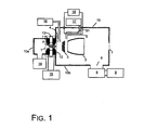
- Figure 1 is a schematic sectional view of the basic arrangement of an EUV radiation producing device of the discharge produced plasma type for which the invention is used,
- Figure 2(a) is a cross-sectional view of a first embodiment of the arrangement of the treatment unit in accordance with the invention
- Figure 2(b) shows an outside view of a heat treatment part
- Figure 3(a) is a cross-sectional view of a second embodiment of the arrangement of the treatment unit of the invention.
- Figure 3(b) shows a cross section of a heating structure of the treatment unit of Figure 3(a);
- Figure 3(c) shows a top view of the heating structure shown in Figure 3(b);
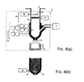
- Figure 4(a) is a cross-sectional view of a third embodiment of the arrangement of the treatment unit
- Figure 4(b) shows an outside view of the cooling treatment part of the Figure 4(a) arrangement
- Figure 5(a) shows a cross section of a fourth embodiment of the arrangement of the treatment unit of the invention
- Figure 5(b) shows a cross section of an endothermic structure of the Figure 5(a) arrangement
- Figure 5(c) is a top view of the endothermic structure of Figure 5(b).
- Figure 6 shows a schematic view of an arrangement in which a plasma is used to produce the hydrogen radicals in the treatment unit according to the embodiments of the invention.
- FIG. 1 is a schematic sectional view of the basic arrangement of an EUV radiation producing device of the DPP type in accordance with the invention.
- the radiation source chamber 10 which serves as the vacuum vessel
- the first electrode 11, the second electrode 12, and the insulator 13 which are arranged in this way compose the discharge part 1 of the EUV producing device.
- the first electrode 11, the second electrode 12 and the insulator 13 are annular and arranged such that their through openings run essentially coaxially to one another.
- the first electrode 11 and the second electrode 12 are connected to a pulsed power supply 15 and are electrically insulated from one another by an insulator 13.
- the first electrode 11 and the second electrode 12 are made, for example, of a metal with a high melting point, such as tungsten, molybdenum, tantalum or the like.
- the insulator 13 is made of a ceramic with a high plasma tolerance, such as, for example, silicon nitride, aluminum nitride, boron nitride or the like.
- the radiation source chamber 10 comprises a first chamber 10a and a second chamber 10b.
- a plasma is ignited between the first electrode 11 and the second electrode 12 while supplying of the EUV radiating species, for example, stannane (SnH 4 ) or the like, from a raw material supply unit 14 which is connected to the first chamber 10a to the discharge part 1, the raw material which contains the EUV radiating species is heated and excited, and a plasma P is formed essentially in the middle of the discharge part 1 (middle of the through openings).
- This plasma P emits EUV radiation with a wavelength of 13.5 nm which is used for lithography, only when it has an extremely high density and high temperature. Therefore, for the EUV radiation producing device, a pulsed driving method is used in which momentary discharges are repeated in order to increase the peak power which is supplied to the plasma from the power supply, and thus, to produce a high density and high temperature plasma.
- the EUV radiation from the discharge part 1 is emitted from the EUV radiation exit part 7 via a collector mirror 2 which is located in the second chamber 10b.
- the radiation emerging from the EUV radiation exit part 7 travels to the optical system on the side of an exposure tool (not shown).
- the collector mirror 2 is made in the form of an ellipsoid of rotation or in the form of a paraboloid of rotation and is made of a metallic material, such as nickel or the like. Its reflection surface is coated with a metal, such as ruthenium, molybdenum, rhodium or the like, in order to reflect the EUV radiation with high efficiency.
- the reflection surface is, moreover, formed with a grazing-incidence angle of at most 25°, by which the EUV radiation can be effectively reflected.
- the debris trap 3 is formed, for example, of a metal with a high melting point, such as tungsten, molybdenum or the like.
- a gas curtain nozzle 4 which is connected to a gas supply unit 16 which supplies an inert gas such as helium, argon or the like.
- the inert gas which is supplied from the gas supply unit 16 is supplied to the entrance side of the debris trap 3 by the gas curtain nozzle 4.
- the gas curtain which has been formed in this way prevents the debris from reaching the collector mirror 2 by bending the trajectory of the debris which are released from the discharge part 1 in the direction toward the collector mirror 2, or by reducing the velocity of the debris due to the collisions between the particles at a intentionally high gas pressure local region.
- a thermal catalyst type hydrogen radical producing part 5 is used in which a tungsten filament 51, which has been heated to roughly 1800 °C by a heating power supply 18, is provided with hydrogen gas from a gas supply unit 17 and in which hydrogen radicals are generated by contact and dissociation.
- the collector mirror 2 on which the tin deposits is irradiated with the hydrogen radicals which are produced in the hydrogen radical producing part 5, these hydrogen radicals can react with tin and the tin converts into tin hydride with a high vapor pressure. In this way, the tin is vaporized and eliminated, by which a reduction of the reflectance of the EUV radiation of the collector mirror 2 is prevented.
- the portion of the raw material for supply of tin as the EUV radiating species which does not contribute to producing the high density and high temperature plasma P and the portion of the said raw material which has become unnecessary after the contribution to production of the high density and high temperature plasma P are diffused in the second chamber 10b and at least partially evacuated from an outlet opening 6 as evacuated gas. Furthermore, the tin hydride which deposits on the collector mirror 2 and the like as solid tin and which afterwards reacts with the hydrogen radicals and has been vaporized, evacuated from the outlet opening 6 as evacuated gas.
- the evacuated gas which has been flown from the outlet opening 6 of the radiation source chamber 10 as a vacuum vessel to the treatment unit 8 is subjected to treatment in the treatment unit 8, in which tin and/or a tin compound are separated. Only the evacuated gas which contains neither tin nor a tin compound flows into an evacuation device 9. Different embodiments of this treatment unit 8 are described below.
- Figure 2(a) is a cross section of a first embodiment of the arrangement of the treatment unit 8.
- Figure 2(b) is an outside view of the heating treatment part 8b of the treatment unit 8.
- the treatment unit 8 comprises, for example, a steel tube and has an arrangement of two-stage treatment process to separate the tin and/or tin compound from the evacuated gas which contains tin and/or a tin compound.
- a hydrogen radical treatment part 8a to convert tin and/or a tin compound in the evacuated gas into a hydride and to make it chemically stable stannane.
- the hydrogen radical treatment part 8a for example, there is a mesh texture tungsten filament 19 that extends across the flow path of the evacuated gas.
- a heating power supply 20 is connected to the tungsten filament 19.
- a hydrogen gas supply nozzle 22, which is connected to a hydrogen gas supply unit 21, is arranged such that the hydrogen gas which is released from the hydrogen gas supply nozzle 22 reaches the tungsten filament 19.
- the tin which is converted into tin hydride is defined as tin which exists independently of the phase and its state as a elemental substance (not as a compound) such as, for example, tin (Sn) vapor, tin grains (metallic clusters) such as, for example, Sn x or the like).
- the tin compound which is converted into tin hydride is, for example, tin carbide, tin oxide and the like which are formed by a gaseous phase reaction of the tin (Sn vapor as atomic gas, metallic clusters of Sn x and the like) or of fragments such as SnH, SnH 2 , SnH 3 (hereinafter SnH x ) with water (H 2 O), carbon hydride and the like which remain in the device.
- the fragments of SnH x are tin hydride.
- the tin hydride which is produced in the hydrogen radical treatment part 8a is stannane
- the fragments of SnH x which are not stannane react with the hydrogen radicals and are converted into stannane.
- the fragments of SnH x which are not stannane are also treated as tin compounds which are converted into tin hydride (stannane).
- the tin hydride which is produced in the hydrogen radical treatment part 8a need not always be stannane, but can also be other tin hydride with a high vapor pressure, such as Sn 2 H 6 or the like. This means that it is just required that the hydrogen radical treatment part 8a has the function of converting tin and/or a tin compound which are contained in the evacuated gas into tin hydride with a high vapor pressure and conveying it to the heating treatment part 8b described below and the cooling treatment part 8c described below.
- the heating treatment part 8b to separate stannane from the evacuated gas.
- the heating treatment part 8b has an arrangement in a heating apparatus 23 is wound appressed around the outside of steel tube which becomes the evacuated gas passage, and in which the heating site and the heating apparatus 23 are covered with a heat insulating material 24 in order to prevent heat from dissipating.
- the heating apparatus 23 is connected to a heating power supply 25. If power is supplied to the heating apparatus 23 from the heating power supply 25, the steel tube which the evacuated gas passes through is heated at the area where the heating apparatus 23 is wound appressed.
- the temperature and the pressure of the heated evacuated gas within the steel tube are detected by a temperature sensor 26 and a pressure sensor 27.
- the power supplied to the heating apparatus 23 by the heating power supply 25 is controlled by a control unit 28. Said control is carried out such that the heating treatment part 8b reaches a temperature at which the tin becomes liquid by comparing the data of the temperature and pressure of the evacuated gas which have been detected in the above described manner and the vapor pressure data of the tin which are stored beforehand in the control unit 28 to one another;.
- the stannane which is contained in the evacuated gas and which passes through the steel tube of the evacuated gas passage is thermally decomposed.
- the tin which is produced by the decomposition of the stannane becomes liquid tin which adheres to the inside wall surface of the steel tube of the passage. In this way, the stannane is separated from the evacuated gas.
- the evacuated gas is fed into the evacuation device 9 after separation.
- the liquid tin which is adhering to the wall surface runs down the wall surface of the steel tube and is collected in the lower region of the heating treatment part 8b.
- the bottom of the heating treatment part 8b is coupled via a valve 29 to a collecting-storage vessel 30.
- the liquid tin which gathers at the bottom of the heating treatment part 8b can be transferred to the collecting-storage vessel 30 by opening and shutting the valve 29.
- Figure 3(a) is a cross section of a second embodiment of the arrangement of the treatment unit 8 of the invention.
- Figure 3(b) is a schematic view in which the heating structure 31, of Figure 3(a) is shown by itself.
- Figure 3(c) is a schematic view in which the heating structure 31 which is shown in Figure 3(b) is viewed from above.
- a heating structure 31 which built in a heating apparatus to the frame of stainless steel, ceramic or the like is arranged.
- the heating structure 31 is connected to the heating power supply 25.
- the heating structure 31 is heated.
- the steel tube in the vicinity of the heating structure 31 is covered with a heat insulating material 24 so that heat does not dissipate.
- the heating structure 31 is formed of numerous fins 31, 31a, 31b, 31c... which are designed to enlarge the contact area of the evacuated gas which is flowing through, to achieve heat exchange with high efficiency, and to accrete and collect the tin which is liquefied as a result of heat exchange.
- the fins 31a, 31b, 31c... as is shown in Figure 3(c), are arranged such that their openings become smaller in a radially inward direction when the heating structure 31 is viewed from the upstream side.
- the fins 31a, 31b, 31c ... are furthermore inclined, as is shown in Figure 3(b). They are formed such that the liquid tin adhering to the fins 31a, 31b, 31c... can easily flow down.
- the steel tube is divided into several parts;
- the stannane is separated on the respective steel tube which has been formed by the division; Collection is performed on the respective outlet of the divided steel tube and from which the separated evacuated gas is being released;
- Figure 4(a) is a cross section of a third embodiment of the arrangement of the treatment unit 8 in accordance with the invention.
- Figure 4(b) is an outside view of the cooling treatment part 8c of the treatment unit 8.
- the treatment unit 8 for example, is formed of a steel tube as in the first and second embodiments shown in Figures 2 & 3 and has an arrangement in which a two-stage treatment process is carried out to separate the tin and/or the tin compound from the evacuated gas which contains the tin and/or tin compound.
- the cooling treatment part 8c for separating the stannane which is contained in the evacuated gas.
- the cooling treatment part 8c is arranged such that, a copper pipe 35 is wound appressed around the outside of the steel tube in the area of the evacuated gas passage.
- the steel tube is covered with a heat insulating material 24 in the vicinity of the points to be cooled to prevent the cooling effect from being dissipated.
- the temperature and the pressure of the evacuated gas within the steel tube which is to be cooled are detected by a temperature sensor 26 and a pressure sensor 27, respectively.
- the temperature of the cooling treatment part 8c is adjusted to the temperature at which the stannane is liquefied using a control unit 28 in which the data of the temperature and pressure of the evacuated gas which are detected in the above described manner and the vapor pressure data of the stannane which are stored beforehand in the control unit 28 are compared to one another, so that the stannane which is contained in the evacuated gas and which passes through the steel tube is condensed and is converted into liquid tin. Furthermore, this liquid stannane can be allowed to adhere to the inside wall surface of the steel tube of the passage.
- the stannane is separated from the evacuated gas and the evacuated gas is fed into the evacuation device 9 after separation.
- the liquid stannane which remains on the wall surface of the steel tube runs down along the wall surface and is gathered in the lower region of the cooling treatment part 8c.
- the lower region of the cooling treatment part 8c is coupled via a valve 29 to a collecting-storage vessel 30.
- the liquid stannane which has been collected in the lower region of the cooling treatment part 8c can, therefore, be transferred to the collecting-storage vessel 30 by opening and shutting the valve 29.
- the collecting-storage vessel 30 is located within a cooling basin 34 in which there is a cooling medium 33.
- the collecting-storage vessel 30 is cooled by the cooling medium 33 such that the liquid stannane stored therein is preserved unchanged in the liquid phase state.
- Figure 5(a) is a cross section of a fourth embodiment of the arrangement of the treatment unit 8 of the invention.
- Figure 5(b) is a schematic view in which the endothermic structure shown in Figure 5(a) is shown by itself.
- Figure 5(c) is a schematic view in which the endothermic structure 31 shown in Figure 5(b) is viewed from above.
- the cooling treatment part 8c for example, in the steel tube evacuated gas passage, there is an endothermic structure 36 in which there is a coolant circulation line path in a frame of copper, aluminum or the like.
- a cooling device 32 is connected to the coolant circulation line path of the endothermic structure 36. By supplying a cooling medium from the cooling device 32, the endothermic structure 36 is cooled.
- the steel tube in the vicinity of the endothermic structure 36 is covered with a heat insulating material 24 to prevent the cooling air from being dissipated.
- the endothermic structure 36 has fins 36a, 36b, 36c... which are designed to enlarge the contact area of the evacuated gas which is flowing through, to achieve heat exchange with high efficiency, and to accrete and collect the stannane which is liquefied as a result of heat exchange
- the fins 31a, 31b, 31c... as is shown in Figure 5(c), are arranged such that their openings become smaller in a radially inward direction when the endothermic structure 36 is viewed from the upstream side.
- the fins 36a, 36b, 36c ... are inclined downward, as is shown in Figure 5 (b). They are formed such that the liquid stannane adhering to them can easily flow down.
- hydrogen radicals are produced using a thermal catalyst by the front half of the treatment unit 8 being formed as a hydrogen radical treatment part 8a.
- the process for producing the hydrogen radicals is not especially limited, and hydrogen radicals can also be produced, for example, using an electron beam and a plasma.
- Figure 6 is a cross section of the arrangement in which a plasma is used to produce hydrogen radicals in the hydrogen radical treatment part 8a of the treatment unit 8.
- the treatment unit 8 as in the first to fourth embodiments comprises, for example, a steel tube and has an arrangement in which a two-stage treatment process is carried out to separate the tin and/or tin compound from the evacuated gas which contains tin and/or a tin compound.
- the hydrogen radical treatment part 8a which is located on the side of the vacuum vessel (side of the second chamber 10b) of the treatment unit 8 has an arrangement in which, for example, part of the evacuated gas passage is formed as a silica glass tube in which, on the outside of the silica glass tube 37, there is an induction coil 39 connected to a radio frequency power supply 38 and in which hydrogen gas can be supplied from the hydrogen gas supply nozzle 22 which is located in the hydrogen gas supply unit 21 to the silica glass tube 37.
- the arrangement and the reaction of the heating treatment part 8b which is located on the side of the evacuation device 9 of the treatment unit 8 are identical to the first and second embodiments and therefore are not further described.
- the cooling treatment part 8c according to the third and fourth embodiments can also be used.
- the extreme UV radiation producing device (EUV radiation producing device) of the invention can separate tin and/or a tin compound from the evacuated gas which contains tin and/or a tin compound in the treatment unit. Therefore the period of maintenance and the replacement of the evacuation device can be prolonged and the mean time between repairs of the semiconductor exposure system using the EUV radiation producing device can be shortened.
Landscapes
- Engineering & Computer Science (AREA)
- Physics & Mathematics (AREA)
- Chemical & Material Sciences (AREA)
- Nanotechnology (AREA)
- Plasma & Fusion (AREA)
- Theoretical Computer Science (AREA)
- Mathematical Physics (AREA)
- Crystallography & Structural Chemistry (AREA)
- Optics & Photonics (AREA)
- General Physics & Mathematics (AREA)
- Exposure And Positioning Against Photoresist Photosensitive Materials (AREA)
- Exposure Of Semiconductors, Excluding Electron Or Ion Beam Exposure (AREA)
- X-Ray Techniques (AREA)
- Physical Or Chemical Processes And Apparatus (AREA)
Applications Claiming Priority (1)
| Application Number | Priority Date | Filing Date | Title |
|---|---|---|---|
| JP2005211982A JP4710463B2 (ja) | 2005-07-21 | 2005-07-21 | 極端紫外光発生装置 |
Publications (3)
| Publication Number | Publication Date |
|---|---|
| EP1746865A2 true EP1746865A2 (de) | 2007-01-24 |
| EP1746865A3 EP1746865A3 (de) | 2009-08-26 |
| EP1746865B1 EP1746865B1 (de) | 2010-08-25 |
Family
ID=37114436
Family Applications (1)
| Application Number | Title | Priority Date | Filing Date |
|---|---|---|---|
| EP06015248A Ceased EP1746865B1 (de) | 2005-07-21 | 2006-07-21 | Extrem-UV-Strahlungsquelle |
Country Status (6)
| Country | Link |
|---|---|
| US (1) | US7479645B2 (de) |
| EP (1) | EP1746865B1 (de) |
| JP (1) | JP4710463B2 (de) |
| KR (1) | KR100893817B1 (de) |
| DE (1) | DE602006016378D1 (de) |
| TW (1) | TW200705460A (de) |
Cited By (3)
| Publication number | Priority date | Publication date | Assignee | Title |
|---|---|---|---|---|
| WO2009083175A1 (en) * | 2007-12-27 | 2009-07-09 | Asml Netherlands B.V. | Extreme ultraviolet radiation source and method for producing extreme ultraviolet radiation |
| WO2011036248A1 (en) * | 2009-09-25 | 2011-03-31 | Asml Netherlands B.V. | Source collector apparatus, lithographic apparatus and device manufacturing method |
| EP2157584A3 (de) * | 2008-08-14 | 2011-07-13 | ASML Netherlands B.V. | Strahlungsquelle, Lithografiegerät und Herstellungsverfahren für ein Bauteil |
Families Citing this family (36)
| Publication number | Priority date | Publication date | Assignee | Title |
|---|---|---|---|---|
| JP2006202671A (ja) * | 2005-01-24 | 2006-08-03 | Ushio Inc | 極端紫外光光源装置及び極端紫外光光源装置で発生するデブリの除去方法 |
| JP4888046B2 (ja) | 2006-10-26 | 2012-02-29 | ウシオ電機株式会社 | 極端紫外光光源装置 |
| US20080239262A1 (en) * | 2007-03-29 | 2008-10-02 | Asml Netherlands B.V. | Radiation source for generating electromagnetic radiation and method for generating electromagnetic radiation |
| JP5108367B2 (ja) * | 2007-04-27 | 2012-12-26 | ギガフォトン株式会社 | 極端紫外光源装置 |
| DE102007033701A1 (de) * | 2007-07-14 | 2009-01-22 | Xtreme Technologies Gmbh | Verfahren und Anordnung zur Reinigung von optischen Oberflächen in plasmabasierten Strahlungsquellen |
| JP5191541B2 (ja) * | 2007-08-23 | 2013-05-08 | エーエスエムエル ネザーランズ ビー.ブイ. | 極端紫外線を生成するモジュールおよび方法、並びにリソグラフィ投影装置 |
| US8901521B2 (en) * | 2007-08-23 | 2014-12-02 | Asml Netherlands B.V. | Module and method for producing extreme ultraviolet radiation |
| TWI402628B (zh) * | 2007-08-31 | 2013-07-21 | Cymer Inc | 控管極遠紫外線(euv)光微影裝置腔室間之氣體流動的系統 |
| US7812329B2 (en) * | 2007-12-14 | 2010-10-12 | Cymer, Inc. | System managing gas flow between chambers of an extreme ultraviolet (EUV) photolithography apparatus |
| US7655925B2 (en) | 2007-08-31 | 2010-02-02 | Cymer, Inc. | Gas management system for a laser-produced-plasma EUV light source |
| JP4956825B2 (ja) * | 2007-09-28 | 2012-06-20 | 国立大学法人名古屋大学 | 反射鏡、その製造方法、そのクリーニング方法及び光源装置 |
| NL1036153A1 (nl) * | 2007-11-08 | 2009-05-11 | Asml Netherlands Bv | Method and system for determining a suppression factor of a suppression system and a lithographic apparatus. |
| WO2010004481A1 (en) * | 2008-07-07 | 2010-01-14 | Philips Intellectual Property & Standards Gmbh | Extreme uv radiation generating device comprising a corrosion-resistant material |
| CN102099746B (zh) * | 2008-07-18 | 2013-05-08 | 皇家飞利浦电子股份有限公司 | 包含污染捕获器的极端紫外辐射生成设备 |
| JP5891341B2 (ja) * | 2009-01-13 | 2016-03-23 | ヘルスセンシング株式会社 | プラズマ生成装置及び方法 |
| US8138487B2 (en) * | 2009-04-09 | 2012-03-20 | Cymer, Inc. | System, method and apparatus for droplet catcher for prevention of backsplash in a EUV generation chamber |
| JP5705592B2 (ja) * | 2010-03-18 | 2015-04-22 | ギガフォトン株式会社 | 極端紫外光生成装置 |
| US8872142B2 (en) | 2010-03-18 | 2014-10-28 | Gigaphoton Inc. | Extreme ultraviolet light generation apparatus |
| JP5818528B2 (ja) * | 2011-06-17 | 2015-11-18 | ギガフォトン株式会社 | 極端紫外光生成装置 |
| US8368039B2 (en) * | 2010-04-05 | 2013-02-05 | Cymer, Inc. | EUV light source glint reduction system |
| WO2014127151A1 (en) | 2013-02-14 | 2014-08-21 | Kla-Tencor Corporation | System and method for producing an exclusionary buffer gas flow in an euv light source |
| JP5964400B2 (ja) * | 2014-12-04 | 2016-08-03 | ギガフォトン株式会社 | 極端紫外光源装置及びそのターゲット供給システム |
| DE102017207030A1 (de) * | 2017-04-26 | 2018-10-31 | Carl Zeiss Smt Gmbh | Verfahren zur Reinigung von optischen Elementen für den ultravioletten Wellenlängenbereich |
| US10656539B2 (en) | 2017-11-21 | 2020-05-19 | Taiwan Semiconductor Manufacturing Co., Ltd. | Radiation source for lithography process |
| JP7340524B2 (ja) * | 2018-02-13 | 2023-09-07 | エーエスエムエル ネザーランズ ビー.ブイ. | Euvチャンバにおける構造物表面の洗浄 |
| US10631392B2 (en) * | 2018-04-30 | 2020-04-21 | Taiwan Semiconductor Manufacturing Company, Ltd. | EUV collector contamination prevention |
| JP7340005B2 (ja) | 2019-03-08 | 2023-09-06 | ギガフォトン株式会社 | スズトラップ装置、極端紫外光生成装置、及び電子デバイスの製造方法 |
| KR102806689B1 (ko) | 2019-08-23 | 2025-05-13 | 삼성전자주식회사 | 타겟 잔해물 수집 장치 및 이를 포함하는 극자외선 광원 장치 |
| JP7156331B2 (ja) * | 2020-05-15 | 2022-10-19 | ウシオ電機株式会社 | 極端紫外光光源装置 |
| EP3974905A1 (de) * | 2020-09-25 | 2022-03-30 | ASML Netherlands B.V. | Pumpe |
| KR102897585B1 (ko) * | 2020-09-29 | 2025-12-10 | 삼성전자주식회사 | 극자외선 광원 시스템 |
| US12487531B2 (en) * | 2023-05-04 | 2025-12-02 | Taiwan Semiconductor Manufacturing Company Ltd. | Extreme ultraviolet (EUV) radiation source apparatus, EUV lithography system, and method for generating extreme ultraviolet radiation |
| WO2025108636A1 (en) * | 2023-11-23 | 2025-05-30 | Asml Netherlands B.V. | Scrubber system, euv radiation source and euv utilization system comprising the same, and method of removing contamination |
| WO2025153241A1 (en) * | 2024-01-17 | 2025-07-24 | Asml Netherlands B.V. | Modular gas purification system for radiation source |
| WO2025201973A1 (en) * | 2024-03-28 | 2025-10-02 | Asml Netherlands B.V. | Apparatus for and method of controlling contaminant dispersal in euv radiation source |
| CN118577895B (zh) * | 2024-08-07 | 2024-10-15 | 福建粒量科技有限公司 | 一种cob-led模组流水线用的除锡装置 |
Citations (3)
| Publication number | Priority date | Publication date | Assignee | Title |
|---|---|---|---|---|
| US5991360A (en) | 1997-02-07 | 1999-11-23 | Hitachi, Ltd. | Laser plasma x-ray source, semiconductor lithography apparatus using the same and a method thereof |
| JP2004279246A (ja) | 2003-03-17 | 2004-10-07 | Ushio Inc | 極端紫外光放射源及び半導体露光装置 |
| JP2005015182A (ja) | 2003-06-27 | 2005-01-20 | Hitachi Plant Eng & Constr Co Ltd | チェンの異常検出装置 |
Family Cites Families (9)
| Publication number | Priority date | Publication date | Assignee | Title |
|---|---|---|---|---|
| GB2195070B (en) * | 1986-09-11 | 1991-04-03 | Hoya Corp | Laser plasma x-ray generator capable of continuously generating x-rays |
| US6541786B1 (en) * | 1997-05-12 | 2003-04-01 | Cymer, Inc. | Plasma pinch high energy with debris collector |
| JP2000091095A (ja) * | 1998-09-14 | 2000-03-31 | Nikon Corp | X線発生装置 |
| AU1241401A (en) * | 1999-10-27 | 2001-05-08 | Jmar Research, Inc. | Method and radiation generating system using microtargets |
| US6667484B2 (en) | 2000-07-03 | 2003-12-23 | Asml Netherlands B.V. | Radiation source, lithographic apparatus, device manufacturing method, and device manufactured thereby |
| EP1329772B1 (de) | 2001-12-28 | 2009-03-25 | ASML Netherlands B.V. | Lithographischer Projektionsapparat und Verfahren zur Herstellung eines Artikels |
| DE60323927D1 (de) * | 2002-12-13 | 2008-11-20 | Asml Netherlands Bv | Lithographischer Apparat und Verfahren zur Herstellung einer Vorrichtung |
| US6919573B2 (en) * | 2003-03-20 | 2005-07-19 | Asml Holding N.V | Method and apparatus for recycling gases used in a lithography tool |
| JP2006202671A (ja) * | 2005-01-24 | 2006-08-03 | Ushio Inc | 極端紫外光光源装置及び極端紫外光光源装置で発生するデブリの除去方法 |
-
2005
- 2005-07-21 JP JP2005211982A patent/JP4710463B2/ja not_active Expired - Fee Related
-
2006
- 2006-05-19 TW TW095117918A patent/TW200705460A/zh not_active IP Right Cessation
- 2006-06-22 KR KR1020060056449A patent/KR100893817B1/ko not_active Expired - Fee Related
- 2006-07-21 US US11/459,142 patent/US7479645B2/en active Active
- 2006-07-21 EP EP06015248A patent/EP1746865B1/de not_active Ceased
- 2006-07-21 DE DE602006016378T patent/DE602006016378D1/de active Active
Patent Citations (4)
| Publication number | Priority date | Publication date | Assignee | Title |
|---|---|---|---|---|
| US5991360A (en) | 1997-02-07 | 1999-11-23 | Hitachi, Ltd. | Laser plasma x-ray source, semiconductor lithography apparatus using the same and a method thereof |
| JP2004279246A (ja) | 2003-03-17 | 2004-10-07 | Ushio Inc | 極端紫外光放射源及び半導体露光装置 |
| US6984941B2 (en) | 2003-03-17 | 2006-01-10 | Ushiodenki Kabushiki Kaisha | Extreme UV radiation source and semiconductor exposure device |
| JP2005015182A (ja) | 2003-06-27 | 2005-01-20 | Hitachi Plant Eng & Constr Co Ltd | チェンの異常検出装置 |
Cited By (6)
| Publication number | Priority date | Publication date | Assignee | Title |
|---|---|---|---|---|
| WO2009083175A1 (en) * | 2007-12-27 | 2009-07-09 | Asml Netherlands B.V. | Extreme ultraviolet radiation source and method for producing extreme ultraviolet radiation |
| EP2157584A3 (de) * | 2008-08-14 | 2011-07-13 | ASML Netherlands B.V. | Strahlungsquelle, Lithografiegerät und Herstellungsverfahren für ein Bauteil |
| WO2011036248A1 (en) * | 2009-09-25 | 2011-03-31 | Asml Netherlands B.V. | Source collector apparatus, lithographic apparatus and device manufacturing method |
| CN102576195A (zh) * | 2009-09-25 | 2012-07-11 | Asml荷兰有限公司 | 源收集器设备、光刻设备以及器件制造方法 |
| CN102576195B (zh) * | 2009-09-25 | 2015-01-14 | Asml荷兰有限公司 | 源收集器设备、光刻设备以及器件制造方法 |
| US9091944B2 (en) | 2009-09-25 | 2015-07-28 | Asml Netherlands B.V. | Source collector, lithographic apparatus and device manufacturing method |
Also Published As
| Publication number | Publication date |
|---|---|
| US20070018119A1 (en) | 2007-01-25 |
| EP1746865B1 (de) | 2010-08-25 |
| EP1746865A3 (de) | 2009-08-26 |
| JP4710463B2 (ja) | 2011-06-29 |
| US7479645B2 (en) | 2009-01-20 |
| TW200705460A (en) | 2007-02-01 |
| DE602006016378D1 (de) | 2010-10-07 |
| TWI360137B (de) | 2012-03-11 |
| KR100893817B1 (ko) | 2009-04-20 |
| KR20070012199A (ko) | 2007-01-25 |
| JP2007035660A (ja) | 2007-02-08 |
Similar Documents
| Publication | Publication Date | Title |
|---|---|---|
| EP1746865B1 (de) | Extrem-UV-Strahlungsquelle | |
| US9000404B2 (en) | Systems and methods for optics cleaning in an EUV light source | |
| EP1848004B1 (de) | Spiegel zur Fokussierung von EUV Strahlung und EUV Strahlungsquelle | |
| JP4888046B2 (ja) | 極端紫外光光源装置 | |
| JP5693587B2 (ja) | 放射源コレクタ装置、リソグラフィ装置およびデバイス製造方法 | |
| US7459708B2 (en) | Extreme UV radiation source device and method for eliminating debris which forms within the device | |
| EP1460886B1 (de) | Extrem-UV Strahlungsquelle und Halbleiterbelichtungsgerät | |
| TWI402628B (zh) | 控管極遠紫外線(euv)光微影裝置腔室間之氣體流動的系統 | |
| US20090154642A1 (en) | System managing gas flow between chambers of an extreme ultraviolet (EUV) photolithography apparatus | |
| EP1804555A1 (de) | Extrem-UV-Strahlungsquellenvorrichtung | |
| CN1771072A (zh) | 用于euv光源的集光器 | |
| US7641349B1 (en) | Systems and methods for collector mirror temperature control using direct contact heat transfer | |
| WO2003094581A1 (en) | Method of generating extreme ultraviolet radiation | |
| JP5091130B2 (ja) | Euv光源集光器寿命の改善 | |
| EP1972999B1 (de) | Folien-Falle und extrem-ultraviolet Strahlungsquelle diese Folien-Falle verwendend | |
| US8198612B2 (en) | Systems and methods for heating an EUV collector mirror | |
| Fomenkov et al. | Performance and scaling of a dense plasma focus light source for EUV lithography | |
| JP5182917B2 (ja) | 極端紫外光源装置および極端紫外光源における付着物除去方法 | |
| JP4618013B2 (ja) | 極端紫外光光源装置 | |
| JP2009500795A (ja) | Euv光源のための代替燃料 |
Legal Events
| Date | Code | Title | Description |
|---|---|---|---|
| PUAI | Public reference made under article 153(3) epc to a published international application that has entered the european phase |
Free format text: ORIGINAL CODE: 0009012 |
|
| AK | Designated contracting states |
Kind code of ref document: A2 Designated state(s): AT BE BG CH CY CZ DE DK EE ES FI FR GB GR HU IE IS IT LI LT LU LV MC NL PL PT RO SE SI SK TR |
|
| AX | Request for extension of the european patent |
Extension state: AL BA HR MK YU |
|
| PUAL | Search report despatched |
Free format text: ORIGINAL CODE: 0009013 |
|
| AK | Designated contracting states |
Kind code of ref document: A3 Designated state(s): AT BE BG CH CY CZ DE DK EE ES FI FR GB GR HU IE IS IT LI LT LU LV MC NL PL PT RO SE SI SK TR |
|
| AX | Request for extension of the european patent |
Extension state: AL BA HR MK RS |
|
| 17P | Request for examination filed |
Effective date: 20091123 |
|
| GRAP | Despatch of communication of intention to grant a patent |
Free format text: ORIGINAL CODE: EPIDOSNIGR1 |
|
| AKX | Designation fees paid |
Designated state(s): DE NL |
|
| GRAS | Grant fee paid |
Free format text: ORIGINAL CODE: EPIDOSNIGR3 |
|
| GRAA | (expected) grant |
Free format text: ORIGINAL CODE: 0009210 |
|
| AK | Designated contracting states |
Kind code of ref document: B1 Designated state(s): DE NL |
|
| REG | Reference to a national code |
Ref country code: NL Ref legal event code: T3 |
|
| REF | Corresponds to: |
Ref document number: 602006016378 Country of ref document: DE Date of ref document: 20101007 Kind code of ref document: P |
|
| PLBE | No opposition filed within time limit |
Free format text: ORIGINAL CODE: 0009261 |
|
| STAA | Information on the status of an ep patent application or granted ep patent |
Free format text: STATUS: NO OPPOSITION FILED WITHIN TIME LIMIT |
|
| 26N | No opposition filed |
Effective date: 20110526 |
|
| REG | Reference to a national code |
Ref country code: DE Ref legal event code: R097 Ref document number: 602006016378 Country of ref document: DE Effective date: 20110526 |
|
| PGFP | Annual fee paid to national office [announced via postgrant information from national office to epo] |
Ref country code: NL Payment date: 20160610 Year of fee payment: 11 |
|
| PGFP | Annual fee paid to national office [announced via postgrant information from national office to epo] |
Ref country code: DE Payment date: 20160712 Year of fee payment: 11 |
|
| REG | Reference to a national code |
Ref country code: DE Ref legal event code: R119 Ref document number: 602006016378 Country of ref document: DE |
|
| REG | Reference to a national code |
Ref country code: NL Ref legal event code: MM Effective date: 20170801 |
|
| PG25 | Lapsed in a contracting state [announced via postgrant information from national office to epo] |
Ref country code: NL Free format text: LAPSE BECAUSE OF NON-PAYMENT OF DUE FEES Effective date: 20170801 Ref country code: DE Free format text: LAPSE BECAUSE OF NON-PAYMENT OF DUE FEES Effective date: 20180201 |