EP1747351B1 - Procédé pour faire fonctionner un moteur à combustion interne - Google Patents
Procédé pour faire fonctionner un moteur à combustion interne Download PDFInfo
- Publication number
- EP1747351B1 EP1747351B1 EP05744092A EP05744092A EP1747351B1 EP 1747351 B1 EP1747351 B1 EP 1747351B1 EP 05744092 A EP05744092 A EP 05744092A EP 05744092 A EP05744092 A EP 05744092A EP 1747351 B1 EP1747351 B1 EP 1747351B1
- Authority
- EP
- European Patent Office
- Prior art keywords
- engine
- valve
- intake
- period
- cylinder
- Prior art date
- Legal status (The legal status is an assumption and is not a legal conclusion. Google has not performed a legal analysis and makes no representation as to the accuracy of the status listed.)
- Expired - Lifetime
Links
Images

Classifications
-
- F—MECHANICAL ENGINEERING; LIGHTING; HEATING; WEAPONS; BLASTING
- F02—COMBUSTION ENGINES; HOT-GAS OR COMBUSTION-PRODUCT ENGINE PLANTS
- F02D—CONTROLLING COMBUSTION ENGINES
- F02D13/00—Controlling the engine output power by varying inlet or exhaust valve operating characteristics, e.g. timing
- F02D13/02—Controlling the engine output power by varying inlet or exhaust valve operating characteristics, e.g. timing during engine operation
- F02D13/0223—Variable control of the intake valves only
- F02D13/0226—Variable control of the intake valves only changing valve lift or valve lift and timing
-
- F—MECHANICAL ENGINEERING; LIGHTING; HEATING; WEAPONS; BLASTING
- F02—COMBUSTION ENGINES; HOT-GAS OR COMBUSTION-PRODUCT ENGINE PLANTS
- F02B—INTERNAL-COMBUSTION PISTON ENGINES; COMBUSTION ENGINES IN GENERAL
- F02B21/00—Engines characterised by air-storage chambers
-
- F—MECHANICAL ENGINEERING; LIGHTING; HEATING; WEAPONS; BLASTING
- F02—COMBUSTION ENGINES; HOT-GAS OR COMBUSTION-PRODUCT ENGINE PLANTS
- F02B—INTERNAL-COMBUSTION PISTON ENGINES; COMBUSTION ENGINES IN GENERAL
- F02B23/00—Other engines characterised by special shape or construction of combustion chambers to improve operation
- F02B23/02—Other engines characterised by special shape or construction of combustion chambers to improve operation with compression ignition
- F02B23/04—Other engines characterised by special shape or construction of combustion chambers to improve operation with compression ignition the combustion space being subdivided into two or more chambers
-
- F—MECHANICAL ENGINEERING; LIGHTING; HEATING; WEAPONS; BLASTING
- F02—COMBUSTION ENGINES; HOT-GAS OR COMBUSTION-PRODUCT ENGINE PLANTS
- F02D—CONTROLLING COMBUSTION ENGINES
- F02D13/00—Controlling the engine output power by varying inlet or exhaust valve operating characteristics, e.g. timing
- F02D13/02—Controlling the engine output power by varying inlet or exhaust valve operating characteristics, e.g. timing during engine operation
- F02D13/0257—Independent control of two or more intake or exhaust valves respectively, i.e. one of two intake valves remains closed or is opened partially while the other is fully opened
-
- Y—GENERAL TAGGING OF NEW TECHNOLOGICAL DEVELOPMENTS; GENERAL TAGGING OF CROSS-SECTIONAL TECHNOLOGIES SPANNING OVER SEVERAL SECTIONS OF THE IPC; TECHNICAL SUBJECTS COVERED BY FORMER USPC CROSS-REFERENCE ART COLLECTIONS [XRACs] AND DIGESTS
- Y02—TECHNOLOGIES OR APPLICATIONS FOR MITIGATION OR ADAPTATION AGAINST CLIMATE CHANGE
- Y02T—CLIMATE CHANGE MITIGATION TECHNOLOGIES RELATED TO TRANSPORTATION
- Y02T10/00—Road transport of goods or passengers
- Y02T10/10—Internal combustion engine [ICE] based vehicles
- Y02T10/12—Improving ICE efficiencies
Definitions
- the present invention relates to a method of operating an internal combustion engine.
- EP0095252 proposes using such an auxiliary chamber to trap a variable fraction of the cylinder charge during compression in order to vary the effective compression ratio of the engine.
- Pending patent application PCT/GB2004/001018 proposes using an auxiliary chamber as a buffer chamber in an air hybrid engine vehicle to transfer compressed gases in two steps via the auxiliary chamber to a compressed gas reservoir when the engine is operating as a gas compressor thereby assisting deceleration of the vehicle, and to expand the compressed gases in two steps from the compressed gas reservoir via the auxiliary chamber when the engine is operated as a gas expander thereby assisting acceleration of the vehicle.
- Another pending patent application GB0405828.5 proposes using an auxiliary chamber to vary the compression temperature of the cylinder charge in order to achieve CAI/HCCI combustion and influence the auto-ignition timing.
- a method of operating an internal combustion engine having an engine cylinder with a reciprocating piston, first and second intake ports for admitting gas from an ambient air supply into the engine cylinder, first and second intake valves each arranged between a respective one of the intake ports and the engine cylinder, a non-return valve arranged in the second of the intake ports at a distance from the second intake valve and oriented to allow gas to flow only towards the engine cylinder, and a variable valve actuating system for controlling the opening and closing of at least the second intake valve, the method being characterised in that, in at least one operating mode of the engine, the second intake valve is opened and closed, while the cylinder is fully isolated from the ambient air, to permit gas transfer between the cylinder and an auxiliary chamber temporarily defined by the part of the second intake port lying between the second intake valve and the non-return valve, the second intake valve being opened at a time when the pressure in the auxiliary chamber is greater than the pressure of the ambient air supply such that no gas escapes past the non-return valve.
- Engines are already known in which a non-return valve is arranged upstream of an intake valve in order to improve the breathing of the engine.
- the present invention is based on the realisation that the closed chamber temporarily defined between the intake valve and the non-return valve can serve the same function as the auxiliary chambers required in the previously mentioned prior art references for internal gas exchange.
- the non-return valve in the second intake port will be subjected to a suction pressure from the engine cylinder and will automatically open to permit through-flow of ambient air in the direction towards the engine cylinder.
- the opening and closing timings of the intake valves are altered to briefly connect the second intake port to a local pressure higher than the intake pressure from the ambient air, the second intake port will cease to function as an ambient air flow port but the engine could still operate with air supplied through the first intake port so that there is no significant adverse effect on the running of the engine other than a possible reduction in the volumetric efficiency of the engine.
- the non-return valve is preferably a reed valve mounted in the second intake port for isolating the temporary auxiliary chamber.
- the engine can be made to operate as a variable compression ratio engine by following the method steps of briefly connecting the temporary auxiliary chamber with the engine cylinder by moving the opening and closing timings of the second intake valve to a period after the beginning of the compression period of the engine cycle thereby trapping a variable fraction of the compressed charge in the auxiliary chamber in order to vary the effective compression ratio of the engine.
- auxiliary chamber makes it possible to apply the proposal described in EP0095252 for a variable compression ratio engine. Furthermore, by varying the effective compression ratio, the method may be used in accordance with the proposal described in GB0405828.5 for varying the compression temperature of the cylinder charge in order to achieve CAI/HCCI combustion and influence the auto-ignition timing.
- the engine can be made to operate as an air compressor for absorbing power during vehicle deceleration in a non-firing cycle in the absence of fuel by following the method steps of briefly connecting the said temporary auxiliary chamber with the engine cylinder by moving the opening and closing timings of the second intake valve to a period before the end of the compression period of the engine cycle thereby trapping some compressed air in the auxiliary chamber, followed by briefly connecting the then sealed auxiliary chamber with an external pressurised air reservoir by way of a timed on/off valve provided between the said auxiliary chamber and the said pressurised air reservoir thereby transferring some of the compressed air into the air reservoir.
- the stored compressed air may later be re-used in the air hybrid engine in a variety of ways, such as cranking and re-starting the engine during stop-start operation, boosting the engine with a quick burst of pressurised air during acceleration in order to reduce the response delay from a turbo-charger, injecting secondary air into the engine exhaust for fast catalyst light-off and particulate trap regeneration, and motoring the engine under certain cruising conditions.
- the method of the present invention may be applied in a special combined "crank-fire" cycle for cranking and firing the engine during stop-start operation using the compressed air stored in the external pressurised air reservoir.
- the opening and closing timings of the first and second intake valves are altered in such a way as to isolate the engine cylinder from the ambient air supply by not opening the first intake valve at all (by means of a variable valve actuation system which de-activates the valve), whilst the second intake valve is opened and closed normally during the intake period of the engine cycle with the second intake port also connected to the external pressurised air reservoir by opening the timed on/off valve.
- the non-return valve in the second intake port will remain shut because of the air pressure from the external air reservoir and compressed air will enter the cylinder during the intake period and at the same time drive the piston at high pressure thus producing motoring power for cranking the engine.
- the same air is then compressed in the immediately following compression period and fired with fuel thus producing further combustion power. This would accelerate the engine very rapidly with two torque pulses in the same cycle.
- crank-fire cycle By connecting a whole bank of engine cylinders to a common external pressurised air reservoir according to the above method, the crank-fire cycle will automatically synchronise with the firing sequence of the cylinders, rotating the crankshaft and re-starting the engine instantaneously within just one or two crankshaft revolutions.
- the compressed air from the external air reservoir is switched off and the engine will transition smoothly and naturally to the normal firing mode with the non-return valve in the second intake port now opening automatically for drawing ambient air through the port in the subsequent cycles, followed by re-activation the first intake valve.
- the crank-fire cycle according to internal gas transfer method of the present invention is a very effective process for stop-start operation in an air hybrid engine.
- crank-fire cycle may also be used, during driving, acceleration and quick launch of a vehicle, to supercharge the engine with very high boost of many bars compressed air pressure, albeit for only a brief period of time, producing very high torque in excess of the instantaneous torque normally expected from boosting by a turbocharger, thus eliminating the response delay and exhaust smoke problems caused by turbo-lag.
- the engine may at any time be switched to operate with two through-flow intake ports for maximum volumetric efficiency by moving the opening and closing timings of both the first and second intake valves to the ambient air intake period of the engine cycle.
- variable valve actuation system is used to alter the opening and closing timings of the first and second intake valves.
- VCT variable camshaft timing
- VVLD variable valve lift and duration
- CPS cam profile switching
- de-act valve de-activation
- VCT is achieved by a variable phaser timing pulley driving the camshaft examples of which could be found in many engines such as Ford ® , General Motors ® and Toyota ®
- VVLD is achieved by a variable geometry rocker example of which could be found in BMW ® engines
- CPS is achieved by selective engagement of a cam follower with one of two available fixed cam profiles on a common camshaft example of which could be found in Hyundai ® engines
- valve de-activation is achieved by a latching mechanism with lost motion developed by Eaton Corp for variable displacement engines.
- variable compression ratio engine using a temporary auxiliary chamber created by the present invention may be controlled by VVLD with small valve lift and narrow valve duration in combination with VCT acting on the second intake valve.
- a low-cost air hybrid engine using a temporary auxiliary chamber may be switched between firing mode and compressor mode by VCT or CPS acting on the second intake valve, and also switched to the crank-fire cycle mode during stop-start by valve de-activation acting on the first intake valve.
- another VCT or CPS system acting on the first intake valve may be included in this engine for enhancing high speed performance as used conventionally for this purpose.
- VCT production-proven VCT, VVLD, CPS or de-act hardware are used to achieve extra functionality of variable compression ratio, HCCI/CAI combustion control, and air hybrid operation. This would make the internal gas exchange method of the present invention highly practical, requiring relatively small development effort to realise the potential.
- Figure 1 shows an internal combustion engine having a first and a second intake port 24, 22 working in conjunction with an exhaust port 26 in each cylinder in which each port is controlled by an associated poppet valve 14, 12, 16 timed to open and close during the intake or exhaust period of the engine cycle in order to control the breathing of the engine.
- a non-return reed valve 32 is additionally provided in the second intake port 22 positioned such that the valve 32 automatically shuts in the flow direction away from the engine cylinder 10 when the port 22 and the non-return valve 32 are subjected to a local pressure higher than the delivery pressure from the ambient air.
- the engine also includes a fuel system and an ignition system which are not shown.
- variable valve actuation system (not shown) is provided for the intake valves 12, 14.
- electro-hydraulic or electric-magnetic actuators there is no need to go to such complexity and the present invention may be achieved using simpler, volume production, camshaft actuated variable valve systems such as VCT, VVLD, CPS and valve de-activation.
- the second intake valve 12 is normally timed to open and close during the ambient air intake period of the engine cycle during which the non-return valve 32 is subjected to a suction pressure from the engine cylinder 10 and will automatically open to permit through-flow of air in the flow direction towards the engine cylinder 10.
- the second intake valve 12 When internal gas transfer is required with the cylinder 10 isolated from the ambient air supply, the second intake valve 12 may be moved in timing to open and close during the compression period of the engine cycle, thus subjecting the second intake port 22 and the non-return valve 32 to a local pressure higher than the delivery pressure from the ambient air, whereupon the non-return valve 32 automatically shuts and isolates the end portion of the second intake port 22 to form a temporary auxiliary chamber 30, and internal gas transfer can take place between the auxiliary chamber 30 and the engine cylinder 10.
- the non-return reed valve 32 is designed to have fast response and good sealing against high pressure within the temporary auxiliary chamber 30. It is also designed to permit a high through-flow when there is a suction pressure in the intake port 22.
- the engine is shown at a time when the engine cycle is undergoing compression with the intake valve 14 and the exhaust valve 16 in the closed position.
- the intake valve 12 of the port 22 is shown at this time in the open position, connecting the temporary auxiliary chamber 30 with the engine cylinder 10 and permitting gas transfer internally between the auxiliary chamber 30 and the engine cylinder 10.
- the second intake port 22 will cease to function as an ambient air flow port during the intake period of the engine cycle but the engine will continue to operate with the first intake port 24 and its associated intake valve 14 fully functional as an ambient air flow port so that there is no significant adverse effect in the running of the engine other than a possible reduction in the volumetric efficiency of the engine.
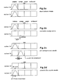
- the internal gas transfer method of the present invention may be used to influence the power conversion process of the engine in a variety of ways described in the following with several examples shown in Figures 2b, 2c, 2d.
- the engine can be made to operate as a variable compression ratio engine by following the method steps of briefly connecting the temporary auxiliary chamber 30 with the engine cylinder 10 by moving the opening and closing timings of the second intake valve 12 to a period after the beginning of the compression period of the engine cycle thereby trapping a variable fraction of the compressed charge in the auxiliary chamber 30 in order to vary the effective compression ratio of the engine.
- a production-proven VVLD valve actuation system in combination with VCT acting on the second intake valve 12 may be used to achieve this as illustrated in Figure 2b.
- variable compression ratio engine may then be used according to the proposal described in GB0405828.5 for varying the compression temperature of the cylinder charge in order to achieve CAI/HCCI combustion and influence the auto-ignition timing.
- the engine can be made to operate as an air compressor for absorbing power during deceleration in a non-firing cycle in the absence of fuel by following the method steps of briefly connecting the temporary auxiliary chamber 30 with the engine cylinder 10 by moving the opening and closing timings of the second intake valve 12 to a period before the end of the compression period of the engine cycle thereby trapping some compressed air in the auxiliary chamber 30, followed by briefly connecting the then sealed auxiliary chamber 30 with an external pressurised air reservoir 36 by way of a timed on/off valve 34 provided between the auxiliary chamber 30 and the pressurised air reservoir 36 thereby transferring some of the compressed air into the air reservoir 36.
- a production-proven VCT or CPS valve actuation system acting on the second intake valve 12 may be used to achieve this as illustrated in Figure 2c.
- the stored compressed air may later be re-used in the air hybrid engine in a variety of ways, such as cranking and re-starting the engine during stop-start operation, boosting the engine with a quick burst of pressurised air during acceleration for reducing the response delay from a turbo-charger, injecting secondary air into the engine exhaust for fast catalyst light-off and particulate trap regeneration, and motoring the engine under certain cruising conditions.
- the internal gas exchange method of the present invention may be applied in a combined "crank-fire" cycle for cranking and firing the engine during stop-start operation using the compressed air stored in the external pressurised air reservoir 36.
- the opening and closing timings of the first and second intake valves are altered in such a way as to isolate the engine cylinder from the ambient air supply by not opening the first intake valve 14 at all (valve de-activation), whilst the second intake valve 12 is opened and closed normally during the intake period of the engine cycle with the second intake port 22 also connected to the external pressurised air reservoir 36 by opening the timed on/off valve 34.
- the non-return valve 32 in the second intake port 22 will remain shut because of the air pressure from the external air reservoir 36 and compressed air will enter the cylinder 10 during the intake period and at the same time drive downwards the piston 20 at high pressure thus producing motoring power for cranking the engine.
- the same air is then compressed in the immediately following compression period and fired with fuel thus producing further combustion power. This would accelerate the engine very rapidly with two torque pulses in the same cycle.
- a production-proven valve de-activation system acting on the first intake valve 14 may be used to achieve this as illustrated in Figure 2d.
- crank-fire cycle will automatically synchronise with the firing sequence of the cylinders, rotating the crankshaft and re-starting the engine instantaneously within just one or two crankshaft revolutions.
- the compressed air from the external air reservoir 36 is switched off and the engine will transition smoothly and naturally to the normal firing mode with the non-return valve 32 in the second intake port 22 now opening automatically for drawing ambient air through the port 22 in the subsequent cycles, followed by re-activation the first intake valve 14.
- the crank-fire cycle according to internal gas transfer method of the present invention is a very effective process for stop-start operation in an air hybrid engine.
- crank-fire cycle may also be used, during driving, acceleration and quick launch of a vehicle, to supercharge the engine with very high boost of many bars compressed air pressure, albeit for only a brief period of time, producing very high torque in excess of the instantaneous torque normally expected from boosting by a turbocharger, thus eliminating the response delay and exhaust smoke problems caused by turbo-lag.
- the engine may at any time be switched to operate with two through-flow intake ports 24, 22 for maximum volumetric efficiency in the firing mode by moving the opening and closing timings of both the first and second intake valves 14, 12 to the ambient air intake period of the engine cycle as illustrated in Figure 2a.
- VCT production-proven VCT, VVLD, CPS or de-act hardware are used to achieve extra functionality of variable compression ratio, HCCI/CAI combustion control, and air hybrid operation. This would make the internal gas exchange method of the present invention highly practical, requiring relatively small development effort to realise the potential.
- the second intake valve 12 may be opened and closed twice in each engine cycle, once during the ambient air intake period, and again after the cylinder 10 is isolated from the ambient air supply, thus combining the valve functions of Figures 2a and 2b for full volumetric efficiency and variable compression ratio, and combining the valve functions of Figures 2a and 2c for full volumetric efficiency and compressor mode.
Landscapes
- Engineering & Computer Science (AREA)
- Chemical & Material Sciences (AREA)
- Combustion & Propulsion (AREA)
- Mechanical Engineering (AREA)
- General Engineering & Computer Science (AREA)
- Output Control And Ontrol Of Special Type Engine (AREA)
- Valve Device For Special Equipments (AREA)
- Cylinder Crankcases Of Internal Combustion Engines (AREA)
- Valve-Gear Or Valve Arrangements (AREA)
Claims (10)
- Procédé de fonctionnement d'un moteur à combustion interne, comportant
un cylindre de moteur (10) comportant un piston effectuant un mouvement de va -et -vient (20),
des premier et second orifices d'admission (24, 22) destinés à recevoir un gaz provenant d'une alimentation en air ambiant dans le cylindre du moteur,
des première et seconde soupapes d'admission (14, 12) agencées chacune entre un orifice respectif des orifices d'admission (24, 22) et le cylindre de moteur (10),
une soupape de non-retour (32) agencée dans le second des orifices d'admission (22) à une distance de la seconde soupape d'admission (12) et orientée pour permettre au gaz de circuler uniquement vers le cylindre de moteur (10), et
un système d'actionnement de soupape variable destiné à commander l'ouverture et la fermeture d'au moins la seconde soupape d'admission (12),
le procédé étant caractérisé en ce que, dans au moins un mode de fonctionnement du moteur, la seconde soupape d'admission (12) est ouverte et fermée, alors que le cylindre (10) est totalement isolé de l'air ambiant, pour permettre un transfert de gaz entre le cylindre (10) et une chambre auxiliaire (30) temporairement définie par la partie du second orifice d'admission (22) se situant entre la seconde soupape d'admission (12) et la soupape de non-retour (32), la seconde soupape d'admission (12) étant ouverte à un instant lorsque la pression dans la chambre auxiliaire (30) est supérieure à la pression de l'alimentation en air ambiant de telle sorte qu'aucun gaz ne s'échappe en passant la soupape de non-retour (32). - Procédé selon la revendication 1, dans lequel le moteur présente un mode de fonctionnement à taux de compression variable qui comprend l'ouverture et la fermeture de la seconde soupape d'admission (12) après le début de la période de compression du cycle moteur pour piéger une fraction variable de la charge comprimée dans la chambre auxiliaire (30) de manière à faire varier le taux de compression effectif du moteur.
- Procédé selon la revendication 2, dans lequel le taux de compression effectif du moteur est commandé pour faire varier la température de compression de la charge du cylindre de manière à réaliser une combustion CAI/HCCI et un effet sur le calage d'allumage automatique.
- Procédé selon l'une quelconque des revendications précédentes, dans lequel le moteur présente un mode de fonctionnement dans lequel il sert à emmagasiner de l'air comprimé dans le réservoir (36) relié par une vanne pouvant être commandée sélectivement (34) à la chambre auxiliaire (30), dans lequel mode aucun carburant n'est fourni au cylindre, la seconde soupape d'admission (12) est ouverte et fermée au cours de la période de compression pour stocker une masse comprimée d'air à l'intérieur de la chambre auxiliaire (30) et la vanne pouvant être commandée sélectivement (34) est par la suite ouverte pour transférer l'air comprimé de la chambre auxiliaire (30) vers le réservoir (36).
- Procédé selon la revendication 4, dans lequel le moteur présente un mode de fonctionnement dans lequel l'air comprimé provenant du réservoir (36) est employé pour entraîner le moteur, où la vanne pouvant être commandée sélectivement (34) est ouverte pour mettre sous pression la chambre auxiliaire (30) et la seconde soupape d'admission (12) est ensuite ouverte au cours d'une période durant laquelle le piston (20) se déplace vers le point mort bas.
- Procédé selon la revendication 5, dans lequel la seconde soupape d'admission (12) est ouverte au cours d'une période d'admission du cycle de combustion du moteur pour entraîner et suralimenter le cylindre du moteur (10), la période d'admission étant suivie d'une période de compression et d'une combustion de charge.
- Procédé selon la revendication 5, dans lequel le moteur présente un mode de fonctionnement dans lequel il fonctionne comme un moteur à air comprimé entraîné seulement par l'air comprimé provenant du réservoir (36), dans lequel mode la seconde soupape d'admission (12) est ouverte et fermée au cours d'au moins l'une de la période d'admission et de la période de détente et aucun carburant n'est fourni au moteur.
- Procédé selon l'une quelconque des revendications précédentes, lorsqu'il est appliqué à un moteur comportant un système d'actionnement de soupape variable commandé par came employant un ou plusieurs systèmes parmi la levée et la durée de soupape variable (VVLD), la synchronisation d'arbre à cames variable (VCT), la commutation de profil de came (CPS) et la désactivation de soupape.
- Procédé selon la revendication 1, dans lequel le moteur comporte un système d'actionnement de soupape commandé électriquement et/ou hydrauliquement et un mode de fonctionnement à taux de compression variable dans lequel mode la seconde soupape d'admission (12) est ouverte et fermée deux fois dans chaque cycle moteur, une fois au cours de la période d'admission et de nouveau dans une période après le début de, la période de compression.
- Procédé selon la revendication 1, dans lequel le moteur comporte un système d'actionnement de soupape commandé électriquement et/ou hydrauliquement et un mode de fonctionnement dans lequel le moteur sert à comprimer l'air dans un réservoir (36) relié par une vanne pouvant être commandée sélectivement (34) vers la chambre auxiliaire (30), dans lequel mode la seconde soupape d'admission (12) est ouverte et fermée deux fois dans chaque cycle moteur, une fois au cours de la période d'admission, et de nouveau dans une période avant la fin de la période de compression.
Applications Claiming Priority (3)
| Application Number | Priority Date | Filing Date | Title |
|---|---|---|---|
| GBGB0411359.3A GB0411359D0 (en) | 2004-05-21 | 2004-05-21 | Engine internal gas transfer method |
| GB0415421A GB2414275A (en) | 2004-05-21 | 2004-07-09 | Engine internal gas transfer method |
| PCT/GB2005/050068 WO2005113947A1 (fr) | 2004-05-21 | 2005-05-17 | Procédé pour faire fonctionner un moteur à combustion interne |
Publications (2)
| Publication Number | Publication Date |
|---|---|
| EP1747351A1 EP1747351A1 (fr) | 2007-01-31 |
| EP1747351B1 true EP1747351B1 (fr) | 2007-08-29 |
Family
ID=34970033
Family Applications (1)
| Application Number | Title | Priority Date | Filing Date |
|---|---|---|---|
| EP05744092A Expired - Lifetime EP1747351B1 (fr) | 2004-05-21 | 2005-05-17 | Procédé pour faire fonctionner un moteur à combustion interne |
Country Status (5)
| Country | Link |
|---|---|
| US (1) | US7380525B2 (fr) |
| EP (1) | EP1747351B1 (fr) |
| AT (1) | ATE371806T1 (fr) |
| DE (1) | DE602005002267T2 (fr) |
| WO (1) | WO2005113947A1 (fr) |
Cited By (1)
| Publication number | Priority date | Publication date | Assignee | Title |
|---|---|---|---|---|
| WO2010046826A1 (fr) * | 2008-10-23 | 2010-04-29 | Brunel University | Procédé de démarrage d'un moteur à combustion interne |
Families Citing this family (11)
| Publication number | Priority date | Publication date | Assignee | Title |
|---|---|---|---|---|
| DE102007018775B4 (de) | 2007-04-20 | 2020-04-23 | Ford Global Technologies, Llc | System und Verfahren für adaptive Steuerung von Stößelschalten bei variablem Ventilhub |
| US7689344B2 (en) * | 2007-06-08 | 2010-03-30 | Gm Global Technology Operations, Inc. | Method and apparatus for controlling transitions in an engine having multi-step valve lift |
| DE112008002096B4 (de) * | 2007-08-17 | 2021-04-29 | Borgwarner Inc. | Aufladungsunterstützungssystem |
| US7715974B2 (en) * | 2007-10-09 | 2010-05-11 | Ford Global Technologies, Llc | Method for controlling air-fuel ratio for an alternating valve engine |
| GB0800720D0 (en) | 2008-01-16 | 2008-02-20 | Ma Thomas T H | Air hybrid vehicle |
| GB2457917A (en) | 2008-02-28 | 2009-09-02 | Univ Brunel | I.c engine air hybrid vehicle |
| EP2389504A4 (fr) * | 2009-01-23 | 2013-08-07 | Turbo Innovation Llc | Cycle de moteur à combustion interne |
| ES2425094T3 (es) * | 2009-08-03 | 2013-10-11 | Eth Zurich | Motor de émbolo alternativo turbocargado, con un tanque a presión conectado para superar el retraso del turbo, y un método para el funcionamiento de dicho motor |
| DE102012219432A1 (de) | 2012-10-24 | 2014-04-24 | Bayerische Motoren Werke Aktiengesellschaft - BMW AG | Kraftfahrzeug mit einer Brennkraftmaschine mit einem Druckgastank |
| DE102013215851A1 (de) * | 2013-08-12 | 2015-02-12 | Bayerische Motoren Werke Aktiengesellschaft | Luftfederungsvorrichtung für ein Fahrzeug mit einem Verbrennungsmotor |
| DE102016219101B4 (de) * | 2016-09-30 | 2021-05-06 | Erwin Junker Grinding Technology A.S. | Hubkolben-verbrennungskraftmaschine mit vorrichtung zum steigern ihres drehmomentes |
Family Cites Families (7)
| Publication number | Priority date | Publication date | Assignee | Title |
|---|---|---|---|---|
| GB2122251A (en) | 1982-05-25 | 1984-01-11 | Ford Motor Co | Variable effective compression ratio internal combustion engine |
| JPS60116822A (ja) | 1983-11-29 | 1985-06-24 | Nissan Motor Co Ltd | 内燃機関の吸気弁作動装置 |
| JP3911912B2 (ja) * | 1999-06-23 | 2007-05-09 | 株式会社日立製作所 | エンジン制御システム及び制御方法 |
| JP4453220B2 (ja) | 2001-05-14 | 2010-04-21 | 株式会社デンソー | ディーゼルエンジンの制御装置 |
| JP2003049682A (ja) | 2001-08-08 | 2003-02-21 | Toyota Motor Corp | 内燃機関の制御装置 |
| US6769392B2 (en) * | 2001-12-20 | 2004-08-03 | Caterpillar Inc | Variable valve timing in a homogenous charge compression ignition engine |
| JP3861789B2 (ja) * | 2002-10-03 | 2006-12-20 | 日産自動車株式会社 | 内燃機関の吸気装置 |
-
2005
- 2005-05-17 EP EP05744092A patent/EP1747351B1/fr not_active Expired - Lifetime
- 2005-05-17 DE DE602005002267T patent/DE602005002267T2/de not_active Expired - Lifetime
- 2005-05-17 US US11/569,281 patent/US7380525B2/en not_active Expired - Fee Related
- 2005-05-17 WO PCT/GB2005/050068 patent/WO2005113947A1/fr not_active Ceased
- 2005-05-17 AT AT05744092T patent/ATE371806T1/de not_active IP Right Cessation
Cited By (3)
| Publication number | Priority date | Publication date | Assignee | Title |
|---|---|---|---|---|
| WO2010046826A1 (fr) * | 2008-10-23 | 2010-04-29 | Brunel University | Procédé de démarrage d'un moteur à combustion interne |
| GB2476435A (en) * | 2008-10-23 | 2011-06-22 | Univ Brunel | Method of starting an internal combustion engine |
| GB2476435B (en) * | 2008-10-23 | 2013-01-09 | Univ Brunel | Method of starting an internal combustion engine |
Also Published As
| Publication number | Publication date |
|---|---|
| DE602005002267D1 (de) | 2007-10-11 |
| ATE371806T1 (de) | 2007-09-15 |
| US20070246006A1 (en) | 2007-10-25 |
| US7380525B2 (en) | 2008-06-03 |
| WO2005113947A1 (fr) | 2005-12-01 |
| EP1747351A1 (fr) | 2007-01-31 |
| DE602005002267T2 (de) | 2008-05-29 |
Similar Documents
| Publication | Publication Date | Title |
|---|---|---|
| EP2245281B1 (fr) | Moteur destiné à un véhicule hybride à air comprimé | |
| US7231998B1 (en) | Operating a vehicle with braking energy recovery | |
| US6152104A (en) | Integrated lost motion system for retarding and EGR | |
| JP2001527182A (ja) | 弁積極動力作動を伴うエンジン・ブレーキング | |
| EP1747351B1 (fr) | Procédé pour faire fonctionner un moteur à combustion interne | |
| US6769393B2 (en) | Valve system for internal combustion engine | |
| GB2469939A (en) | Split-cycle engines | |
| CN100545425C (zh) | 操作内燃机的方法 | |
| GB2403772A (en) | Regenerative air hybrid engine comprising an internal combustion engine connected to a compressed air storage tank via shut-off valves | |
| US6622694B2 (en) | Reduced noise engine compression release braking | |
| WO2004080744A1 (fr) | Moteur hybride a air regeneratif | |
| US20110214632A1 (en) | Hydro-mechanical variable valve actuation | |
| GB2430975A (en) | Energy control valve for air hybrid engine | |
| JP2003138943A (ja) | 二サイクル内燃機関 | |
| US10487704B2 (en) | System for variable actuation of a valve of an internal-combustion engine | |
| CN116391075A (zh) | 尤其是机动车的内燃机的运行方法 | |
| WO2010046826A1 (fr) | Procédé de démarrage d'un moteur à combustion interne | |
| CN111448378B (zh) | 用于控制内燃发动机装置的方法 | |
| EP1920143B1 (fr) | Procede de commande des soupapes d admission et d echappement d un moteur, et moteur a combustion interne incorporant ces soupapes | |
| Vasile et al. | Rapid start of hybrid pneumatic engines | |
| JP4710808B2 (ja) | 内燃機関の制御装置 | |
| Lee et al. | The performance characteristics of an production oriented air hybrid powertrain | |
| GB2545203A (en) | A method of operating an automotive system for powering a vehicle | |
| MXPA00004934A (en) | Integrated lost motion system for retarding and egr |
Legal Events
| Date | Code | Title | Description |
|---|---|---|---|
| PUAI | Public reference made under article 153(3) epc to a published international application that has entered the european phase |
Free format text: ORIGINAL CODE: 0009012 |
|
| 17P | Request for examination filed |
Effective date: 20061108 |
|
| AK | Designated contracting states |
Kind code of ref document: A1 Designated state(s): AT BE BG CH CY CZ DE DK EE ES FI FR GB GR HU IE IS IT LI LT LU MC NL PL PT RO SE SI SK TR |
|
| GRAP | Despatch of communication of intention to grant a patent |
Free format text: ORIGINAL CODE: EPIDOSNIGR1 |
|
| GRAS | Grant fee paid |
Free format text: ORIGINAL CODE: EPIDOSNIGR3 |
|
| GRAA | (expected) grant |
Free format text: ORIGINAL CODE: 0009210 |
|
| AK | Designated contracting states |
Kind code of ref document: B1 Designated state(s): AT BE BG CH CY CZ DE DK EE ES FI FR GB GR HU IE IS IT LI LT LU MC NL PL PT RO SE SI SK TR |
|
| DAX | Request for extension of the european patent (deleted) | ||
| REG | Reference to a national code |
Ref country code: GB Ref legal event code: FG4D |
|
| REG | Reference to a national code |
Ref country code: CH Ref legal event code: EP |
|
| REG | Reference to a national code |
Ref country code: IE Ref legal event code: FG4D |
|
| REF | Corresponds to: |
Ref document number: 602005002267 Country of ref document: DE Date of ref document: 20071011 Kind code of ref document: P |
|
| PG25 | Lapsed in a contracting state [announced via postgrant information from national office to epo] |
Ref country code: LT Free format text: LAPSE BECAUSE OF FAILURE TO SUBMIT A TRANSLATION OF THE DESCRIPTION OR TO PAY THE FEE WITHIN THE PRESCRIBED TIME-LIMIT Effective date: 20070829 Ref country code: IS Free format text: LAPSE BECAUSE OF FAILURE TO SUBMIT A TRANSLATION OF THE DESCRIPTION OR TO PAY THE FEE WITHIN THE PRESCRIBED TIME-LIMIT Effective date: 20071229 Ref country code: FI Free format text: LAPSE BECAUSE OF FAILURE TO SUBMIT A TRANSLATION OF THE DESCRIPTION OR TO PAY THE FEE WITHIN THE PRESCRIBED TIME-LIMIT Effective date: 20070829 Ref country code: ES Free format text: LAPSE BECAUSE OF FAILURE TO SUBMIT A TRANSLATION OF THE DESCRIPTION OR TO PAY THE FEE WITHIN THE PRESCRIBED TIME-LIMIT Effective date: 20071210 Ref country code: NL Free format text: LAPSE BECAUSE OF FAILURE TO SUBMIT A TRANSLATION OF THE DESCRIPTION OR TO PAY THE FEE WITHIN THE PRESCRIBED TIME-LIMIT Effective date: 20070829 |
|
| NLV1 | Nl: lapsed or annulled due to failure to fulfill the requirements of art. 29p and 29m of the patents act | ||
| ET | Fr: translation filed | ||
| PG25 | Lapsed in a contracting state [announced via postgrant information from national office to epo] |
Ref country code: CH Free format text: LAPSE BECAUSE OF FAILURE TO SUBMIT A TRANSLATION OF THE DESCRIPTION OR TO PAY THE FEE WITHIN THE PRESCRIBED TIME-LIMIT Effective date: 20070829 Ref country code: PL Free format text: LAPSE BECAUSE OF FAILURE TO SUBMIT A TRANSLATION OF THE DESCRIPTION OR TO PAY THE FEE WITHIN THE PRESCRIBED TIME-LIMIT Effective date: 20070829 Ref country code: AT Free format text: LAPSE BECAUSE OF FAILURE TO SUBMIT A TRANSLATION OF THE DESCRIPTION OR TO PAY THE FEE WITHIN THE PRESCRIBED TIME-LIMIT Effective date: 20070829 Ref country code: LI Free format text: LAPSE BECAUSE OF FAILURE TO SUBMIT A TRANSLATION OF THE DESCRIPTION OR TO PAY THE FEE WITHIN THE PRESCRIBED TIME-LIMIT Effective date: 20070829 |
|
| REG | Reference to a national code |
Ref country code: CH Ref legal event code: PL |
|
| PG25 | Lapsed in a contracting state [announced via postgrant information from national office to epo] |
Ref country code: BE Free format text: LAPSE BECAUSE OF FAILURE TO SUBMIT A TRANSLATION OF THE DESCRIPTION OR TO PAY THE FEE WITHIN THE PRESCRIBED TIME-LIMIT Effective date: 20070829 |
|
| PG25 | Lapsed in a contracting state [announced via postgrant information from national office to epo] |
Ref country code: GR Free format text: LAPSE BECAUSE OF FAILURE TO SUBMIT A TRANSLATION OF THE DESCRIPTION OR TO PAY THE FEE WITHIN THE PRESCRIBED TIME-LIMIT Effective date: 20071130 Ref country code: DK Free format text: LAPSE BECAUSE OF FAILURE TO SUBMIT A TRANSLATION OF THE DESCRIPTION OR TO PAY THE FEE WITHIN THE PRESCRIBED TIME-LIMIT Effective date: 20070829 |
|
| PG25 | Lapsed in a contracting state [announced via postgrant information from national office to epo] |
Ref country code: PT Free format text: LAPSE BECAUSE OF FAILURE TO SUBMIT A TRANSLATION OF THE DESCRIPTION OR TO PAY THE FEE WITHIN THE PRESCRIBED TIME-LIMIT Effective date: 20080129 Ref country code: SK Free format text: LAPSE BECAUSE OF FAILURE TO SUBMIT A TRANSLATION OF THE DESCRIPTION OR TO PAY THE FEE WITHIN THE PRESCRIBED TIME-LIMIT Effective date: 20070829 Ref country code: CZ Free format text: LAPSE BECAUSE OF FAILURE TO SUBMIT A TRANSLATION OF THE DESCRIPTION OR TO PAY THE FEE WITHIN THE PRESCRIBED TIME-LIMIT Effective date: 20070829 |
|
| PG25 | Lapsed in a contracting state [announced via postgrant information from national office to epo] |
Ref country code: SE Free format text: LAPSE BECAUSE OF FAILURE TO SUBMIT A TRANSLATION OF THE DESCRIPTION OR TO PAY THE FEE WITHIN THE PRESCRIBED TIME-LIMIT Effective date: 20071129 Ref country code: RO Free format text: LAPSE BECAUSE OF FAILURE TO SUBMIT A TRANSLATION OF THE DESCRIPTION OR TO PAY THE FEE WITHIN THE PRESCRIBED TIME-LIMIT Effective date: 20070829 |
|
| PLBE | No opposition filed within time limit |
Free format text: ORIGINAL CODE: 0009261 |
|
| STAA | Information on the status of an ep patent application or granted ep patent |
Free format text: STATUS: NO OPPOSITION FILED WITHIN TIME LIMIT |
|
| 26N | No opposition filed |
Effective date: 20080530 |
|
| PG25 | Lapsed in a contracting state [announced via postgrant information from national office to epo] |
Ref country code: MC Free format text: LAPSE BECAUSE OF NON-PAYMENT OF DUE FEES Effective date: 20080531 |
|
| PG25 | Lapsed in a contracting state [announced via postgrant information from national office to epo] |
Ref country code: EE Free format text: LAPSE BECAUSE OF FAILURE TO SUBMIT A TRANSLATION OF THE DESCRIPTION OR TO PAY THE FEE WITHIN THE PRESCRIBED TIME-LIMIT Effective date: 20070829 |
|
| PG25 | Lapsed in a contracting state [announced via postgrant information from national office to epo] |
Ref country code: IE Free format text: LAPSE BECAUSE OF NON-PAYMENT OF DUE FEES Effective date: 20080519 |
|
| PG25 | Lapsed in a contracting state [announced via postgrant information from national office to epo] |
Ref country code: SI Free format text: LAPSE BECAUSE OF FAILURE TO SUBMIT A TRANSLATION OF THE DESCRIPTION OR TO PAY THE FEE WITHIN THE PRESCRIBED TIME-LIMIT Effective date: 20070829 |
|
| PG25 | Lapsed in a contracting state [announced via postgrant information from national office to epo] |
Ref country code: CY Free format text: LAPSE BECAUSE OF FAILURE TO SUBMIT A TRANSLATION OF THE DESCRIPTION OR TO PAY THE FEE WITHIN THE PRESCRIBED TIME-LIMIT Effective date: 20070829 |
|
| PG25 | Lapsed in a contracting state [announced via postgrant information from national office to epo] |
Ref country code: BG Free format text: LAPSE BECAUSE OF FAILURE TO SUBMIT A TRANSLATION OF THE DESCRIPTION OR TO PAY THE FEE WITHIN THE PRESCRIBED TIME-LIMIT Effective date: 20071129 |
|
| PG25 | Lapsed in a contracting state [announced via postgrant information from national office to epo] |
Ref country code: LU Free format text: LAPSE BECAUSE OF NON-PAYMENT OF DUE FEES Effective date: 20080517 Ref country code: HU Free format text: LAPSE BECAUSE OF FAILURE TO SUBMIT A TRANSLATION OF THE DESCRIPTION OR TO PAY THE FEE WITHIN THE PRESCRIBED TIME-LIMIT Effective date: 20080301 |
|
| PG25 | Lapsed in a contracting state [announced via postgrant information from national office to epo] |
Ref country code: TR Free format text: LAPSE BECAUSE OF FAILURE TO SUBMIT A TRANSLATION OF THE DESCRIPTION OR TO PAY THE FEE WITHIN THE PRESCRIBED TIME-LIMIT Effective date: 20070829 |
|
| REG | Reference to a national code |
Ref country code: FR Ref legal event code: PLFP Year of fee payment: 12 |
|
| REG | Reference to a national code |
Ref country code: FR Ref legal event code: PLFP Year of fee payment: 13 |
|
| REG | Reference to a national code |
Ref country code: FR Ref legal event code: PLFP Year of fee payment: 14 |
|
| PGFP | Annual fee paid to national office [announced via postgrant information from national office to epo] |
Ref country code: FR Payment date: 20190509 Year of fee payment: 15 |
|
| PGFP | Annual fee paid to national office [announced via postgrant information from national office to epo] |
Ref country code: DE Payment date: 20200518 Year of fee payment: 16 |
|
| PGFP | Annual fee paid to national office [announced via postgrant information from national office to epo] |
Ref country code: IT Payment date: 20200515 Year of fee payment: 16 Ref country code: GB Payment date: 20200430 Year of fee payment: 16 |
|
| PG25 | Lapsed in a contracting state [announced via postgrant information from national office to epo] |
Ref country code: FR Free format text: LAPSE BECAUSE OF NON-PAYMENT OF DUE FEES Effective date: 20200531 |
|
| REG | Reference to a national code |
Ref country code: DE Ref legal event code: R119 Ref document number: 602005002267 Country of ref document: DE |
|
| GBPC | Gb: european patent ceased through non-payment of renewal fee |
Effective date: 20210517 |
|
| PG25 | Lapsed in a contracting state [announced via postgrant information from national office to epo] |
Ref country code: GB Free format text: LAPSE BECAUSE OF NON-PAYMENT OF DUE FEES Effective date: 20210517 Ref country code: DE Free format text: LAPSE BECAUSE OF NON-PAYMENT OF DUE FEES Effective date: 20211201 |
|
| PG25 | Lapsed in a contracting state [announced via postgrant information from national office to epo] |
Ref country code: IT Free format text: LAPSE BECAUSE OF NON-PAYMENT OF DUE FEES Effective date: 20200517 |
|
| PG25 | Lapsed in a contracting state [announced via postgrant information from national office to epo] |
Ref country code: IT Free format text: LAPSE BECAUSE OF NON-PAYMENT OF DUE FEES Effective date: 20210517 |