EP1747401B1 - Elektronische zündvorrichtung - Google Patents
Elektronische zündvorrichtung Download PDFInfo
- Publication number
- EP1747401B1 EP1747401B1 EP04718378A EP04718378A EP1747401B1 EP 1747401 B1 EP1747401 B1 EP 1747401B1 EP 04718378 A EP04718378 A EP 04718378A EP 04718378 A EP04718378 A EP 04718378A EP 1747401 B1 EP1747401 B1 EP 1747401B1
- Authority
- EP
- European Patent Office
- Prior art keywords
- casing
- cap
- electronic ignitor
- ignitor
- board
- Prior art date
- Legal status (The legal status is an assumption and is not a legal conclusion. Google has not performed a legal analysis and makes no representation as to the accuracy of the status listed.)
- Expired - Lifetime
Links
- 239000011810 insulating material Substances 0.000 claims abstract description 3
- 238000007373 indentation Methods 0.000 claims description 18
- 238000003466 welding Methods 0.000 claims description 5
- 239000000463 material Substances 0.000 claims description 3
- 238000010411 cooking Methods 0.000 description 9
- 238000000034 method Methods 0.000 description 7
- 239000002952 polymeric resin Substances 0.000 description 6
- 229920003002 synthetic resin Polymers 0.000 description 6
- 239000004020 conductor Substances 0.000 description 4
- 238000004519 manufacturing process Methods 0.000 description 4
- 239000007788 liquid Substances 0.000 description 2
- 239000004033 plastic Substances 0.000 description 2
- 229920003023 plastic Polymers 0.000 description 2
- 229920005989 resin Polymers 0.000 description 2
- 239000011347 resin Substances 0.000 description 2
- 238000005476 soldering Methods 0.000 description 2
- 238000010420 art technique Methods 0.000 description 1
- 238000005452 bending Methods 0.000 description 1
- 238000001816 cooling Methods 0.000 description 1
- 238000005520 cutting process Methods 0.000 description 1
- 239000012777 electrically insulating material Substances 0.000 description 1
- 238000009413 insulation Methods 0.000 description 1
- 239000012774 insulation material Substances 0.000 description 1
- 238000005304 joining Methods 0.000 description 1
- 239000011159 matrix material Substances 0.000 description 1
- 239000002184 metal Substances 0.000 description 1
- 239000007787 solid Substances 0.000 description 1
- 229910000859 α-Fe Inorganic materials 0.000 description 1
Images




Classifications
-
- F—MECHANICAL ENGINEERING; LIGHTING; HEATING; WEAPONS; BLASTING
- F23—COMBUSTION APPARATUS; COMBUSTION PROCESSES
- F23Q—IGNITION; EXTINGUISHING-DEVICES
- F23Q3/00—Igniters using electrically-produced sparks
Definitions
- This invention relates to an improved electronic ignitor for gas burners, which provides a cheap and quick assembly of its components as wells as a more functional and quick mounting of the electronic ignitor to the appliance.
- ignitors for lighting gas burners of various appliances such as cooking ranges.
- Those ignitors comprise a circuit, which is connected to at least one output terminal.
- Each of said output terminals is electrically connected to an electrode placed in the close vicinity of the burner.
- the current discharge generated in the circuit creates a high-voltage spark between the electrode and the burner, in order to light the gas.
- the first known electronic ignitor comprises a two-compartment insulating casing; primary and secondary coils placed in one compartment of said casing, and a plate in the other compartment for carrying several electronic parts of the circuit.
- the secondary coils are connected to output terminals and the supply terminals are connected to the plate, which is in turn connected to the primary coil.
- the casing involves integral ducts opening at their one end to the respective compartments, into which output and supply terminals are individually tight fit so as to be insulated.
- the first compartment is filled with liquid polymer resin, which eventually solidifies to fully cover and insulate the assembled parts.
- an electronic gas-lighting device having a casing defined by a cup-shaped body made of electrically insulating material is disclosed.
- An electronic high-voltage-pulse generator is housed in an inner cavity of the casing accessible through a mouth of the cup-shaped body.
- An output terminal is connected to the electronic pulse generator and housed through a respective seating duct formed integrally with a bottom wall of the cup-shaped body.
- a connecting board carrying an electric circuit and extending the full length of the cup-shaped body is positioned substantially closing the mouth, inside the cavity, and carries, on a first face facing the cavity, the electronic pulse generator connected mechanically and electrically to one another and to the board by the board itself and the circuit, so as to be housed in one continuous compartment defined by the inner cavity of the casing and by the connecting board, and so as to be embedded, together with the connecting board, in a matrix of insulating polymer resin which fills the whole of the cavity up to a point flush with the mouth of the cavity.
- the board has at least one through opening enabling the polymer resin to be poured into the casing with the board already in position.
- the two-compartment structure of the previous casings is preserved. However, it differs from the previous art in that it does not comprise any ducts on the casing.
- Two embodiments of the casing is provided, one with two side-by-side compartments closed by a common cap, and another with two compartments one-above the other, such that each closed by a different cap.
- Two assembly components with clips on their ends, project laterally outside from a wall of the casing for removable fitting of the ignitor to the cooking range. These components enable one-step mounting of the electronic ignitor to the conducting surface of the cooking range.
- the secondary coil is wound around an insulating bobbin carcass that is produced with two integral ducts to house the output terminals.
- output terminals are not tight fit to the ducts of the bobbin carcasses but rather, they are fit when the bobbin carcass is newly produced, i.e. when it is still hot, therefore soft.
- the alignment and deformation problems of the prior art techniques are overcome.
- Free-of-ducts design of the casing allows for practical and flawless manufacture and assembly of the ignitor. Hence, the tedious assembly process of the previous technique is replaced with a simple one, which is unlikely to cause any malproductions.
- At least one insulating cap covers the open surface of the casing.
- Said cap is permanently fastened to the casing by ultrasonic welding, in order to avoid unauthorized intervention. It also involves openings in the same number as that of output terminals, so that the ducts of the carcass housing the output terminals extend out of the cap when it is fastened onto the casing. Owing to said openings, output terminals may easily be connected to the electrodes on the cooking range.
- a protrusion extending towards a compartment of the casing and comprising three indentations formed side by side inside said protrusion.
- Said protrusion may or may not be integrally formed with the cap.
- Each of these indentations involves holes for the placement of respective supply and ground terminals. When the cap is positioned on the casing, supply and ground terminals remain inside the said indentations in said protrusion.
- the ignitor of the present invention involves two different embodiments of grounding means, which allow for male-female type easy connection.
- the grounding means is made of a resiliently deformable, electrically conductive metal. Both embodiments enable one-step, simple grounding of the ignitor by simply attaching the grounding terminal to the grounding means. One end of the grounding means is bent for simple attachment to the grounding terminal and the other end extends outside the casing for providing electrical connection with the cooking range.
- the ignitor of the present invention brings another advantage over the prior art, as its grounding process does not require any specific joining such as soldering, welding, etc.
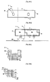
- Figure 1 shows a front view of the casing
- Figure 2 shows a top view of the casing
- Figure 3 shows a front view of the bobbin carcass
- Figure 4 shows a top view of the bobbin carcass
- Figure 5 shows a side view of the bobbin carcass
- Figure 6 shows a front view of the bobbin carcass without output terminal
- Figure 7 shows a top view of the primary coil
- Figure 8 shows a top view of the plate
- Figure 9 shows a front view of the plate
- Figure 10 shows a front view of the output terminal
- Figure 11 shows a side view of the cap
- Figure 12 shows a top view of the cap
- Figure 13 shows A-A section of the cap
- Figures 14 , 15 , and 16 show front, top and side views of one embodiment of the grounding means, respectively;
- Figures 17 and 18 show front and top views of another embodiment of the grounding means, respectively;
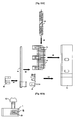
- Figure 19 shows one embodiment of the grounding means assembled to the casing.
- Figure 20 shows another embodiment of the grounding means assembled to the casing.
- Figure 21 s hows a schematic view of the circuit map of the ignitor
- Figure 22 shows an exploded side view of the ignitor
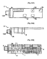
- Figures 23 , 24, 25, and 26 show left, top, front and right views of another embodiment of the ignitor
- Figures 27 and 28 show another embodiment of the ignitor when the top and bottom caps are open;
- Figure 29 shows a section view of another embodiment of the ignitor
- Figures 30 and 31 show top and bottom caps of another embodiment of the ignitor
- Figures 32 and 33 show top and section views of the protrusion of another embodiment of the ignitor
- Figure 34 shows a front view of the plate of another embodiment of the ignitor
- Figures 35 and 36 show front and top views of the casing of an alternative embodiment of the casing
- Figures 37 and 38 show top and front views of the cap of an alternative embodiment of the casing
- Figure 39 shows front view of the assembly of an alternative embodiment of the casing.
- the casing (1) of the electric ignitor is made of an insulating material and is in the form of a rectangular prism. It consists of two lateral (B and D), one front (A), one back (C) and a bottom side (E) and a top side (F).
- the casing (1) is divided into two compartments one for the coils and the other for the plate, separated from each other by an insulating wall, but still enabling the passage of connectors from the primary coil to the plate.
- Figures 1 and 2 illustrate one embodiment of the casing (1) wherein the interior of the casing (1) is divided into two side-by-side compartments (1a and 1b) by a wall (1c) perpendicular to the interior of its bottom side (E).
- the top side (F) of the casing is open and both compartments (1a and 1b) are closed by a common cap (2).
- Two assembly means (1e) which are formed integrally with the casing, project perpendicularly outside from the front side (A).
- the assembly means (1e) are cylindrical or prismatic in shape.
- There exist one or two oppositely placed clips (1f) at the edge of each assembly means (1e). Said clips (1f) are also integral parts of the assembly means (1e).
- Said assembly means (1e) are designed for simple locking of the electronic ignitor to the board of cooking range (7).
- the assembly means (1e) project from the edges at the intersections of the bottom (E) and the two side faces (B and D).
- Each of these assembly means involves two perpendicular planes with a screw hole on each.
- Bobbin carcass (3) ( Figs. 3-6 ), which is made of insulation material, preferably plastics, consists of a hollow (3c) cylindrical part (3b) around which the conductor wire of the secondary coil is wound and two integral (monobloc) ducts (3a) diagonally placed onto the two sides (G and H) of the cylindrical part. Two sides of the carcass (G and H) are parallel to each other.
- one output terminal (4) is fit into a duct (3a). Thanks to the material characteristics of plastics, hot carcass shrinks as it cools down and permanently attaches to the output terminal, thereby eliminating the need to apply force for tight fitting of the terminal.
- This novel fitting method of the output terminals into the ducts of the carcass instead of ducts of the casing as in the prior art also prevents leakage of the polymer resin out of the casing.
- the two free ends of the secondary coil are electrically connected to the respective output terminals (4) after this attachment process.
- a conductor wire (5a) is wound around a solid, cylindrical ferrite core (5b) to form the primary coil (5).
- Primary coil (5) is placed into the cylindrical hole (3c) of the bobbin carcass (3). Therefore, secondary coil is coaxial with the primary coil (5).
- the mounted coils (3 and 5) are put into one compartment (1b) of the casing (1). Then, polymer resin is poured into said compartment (1b) to ensure insulation and fixation of the coils in the casing (1).
- grounding terminal (10) and supply terminals (11, 12) are attached to the plate (6) ( Figs. 8 and 9 ).
- Figures 11 and 12 show the insulating cap (2) having the dimensions to fully cover the open side (F) of the casing (1).
- the total height of the carcass (3) is greater than the total depth of the cap (2) and the casing (1) so that the ducts, and therefore the output terminals (4) extend at least slightly out of the cap through the respective openings (2d, 2e, 2f, and 2g).
- a protrusion (2i) extending in a direction perpendicular to the plane of the cap ( Fig. 13 ). Said protrusion may or may not be produced integrally with the cap. There are three side-by-side indentations (2a, 2b, and 2c) inside said protrusion (2i) each with a hole (2h) at their bases.
- FIGs 14 through 18 illustrate two embodiments of the grounding means (8 and 9).
- Grounding means (8) is manufactured by first cutting it from a resiliently deformable and electrically conductive sheet material, and then bending it into the desired shape. Said means (8) is placed outside the cap so as to form a male-female type connection with the ground terminal. One end of the means provides contact with the terminal residing in its indentation whereas the other end provides contact with the board of the appliance.
- the first embodiment of the grounding means (8) is used together with the assembly means (1e) illustrated in Figures 14-16 .
- This embodiment (8) involves a flat part (8d) to be placed on the cap.
- Another part (8a) extends into an indentation (2a, 2b or 2c) of the cap, perpendicular to said flat part (8d).
- This part (8a) comprises two curved portions for providing contact with the ground terminal in the indentation (2a).
- Grounding means (8) involves a third part (8b) for providing electrical contact with the board (7) of the cooking range.
- said part has a U-shape, which extends parallel to front side (A) of the casing (1) to be trapped between the casing and the board (7) of the cooking range.
- said part (8b) is in the shape of a regular stripe which makes an angle with the front side (A) of the casing (1), again to be trapped between the casing and the board (7).
- Second embodiment of grounding means (9) is used together with assembly means shown in Figure 20 . Similar to the first embodiment, there exist a flat part (9d) to be placed on the cap and another part (9a) extending into an indentation (2a, 2b or 2c) of the cap, perpendicular to said flat part.
- This part (9a) comprises two curved portions for providing contact with the ground terminal in the indentation (2a, 2b or 2c).
- the third part (9b) extends in a direction parallel to one of the lateral sides (B or D), and has the same form as the assembly means.
- grounding means (9) When one end (9a) of the grounding means (9) is attached to the grounding terminal which is housed in indentation (2a) of the cap (2), third part (9b) of the grounding means (9) resides on the assembly means (1e). Two holes (9c) on said part (9b) coincide with the holes of the assembly means. As soon as the casing is assembled to the board of the gas range via screws inserted through the holes on the grounding means and the holes of the assembly means, grounding is established.
- the casing is still divided into two compartments via an insulating interior wall, however said compartments are placed one above the other.
- One compartment houses the plate whereas the other houses the primary and secondary coils.
- the interior wall involves means for the passage of conducting wires of the primary coil from one compartment to the other.
- the two compartments are open to two opposing sides of the casing and are closed by separate caps. Therefore, the cap of one compartment involves openings for the passage of the ducts of the bobbin carcass.
- the cap of the other compartment may have two different embodiments: In one embodiment (not shown in the drawings) said cap involves a protrusion for the supply and ground terminals.
- the protrusion may or may not be an integral part of the respective cap.
- said cap ( Figures 26 and 31 ) is completely flat, in other words free of any protrusions, openings, indentations etc.
- the protrusion (2i) ( Figs. 32 and 33 ) is an independent piece, extending outside through an opening (2j) on a sidewall of the casing ( Figures 23 , 27 and 29 ).
- the supply and ground terminals (10, 11, and 12) are preferably bent perpendicular to the plane of the plate (6) into the indentations (2a, 2b and 2c) of the protrusion (2i).
- Still another embodiment of the invention involves a casing divided into two side-by-side compartments via an insulating wall.
- a lateral side (D) of the casing is open as well ( Fig. 35 and 36 ).
- Said lateral side is adjacent to the compartment (1a) housing the plate (6).
- the cap (2) comprises a section (2k) extending in a direction to close both open sides (D and F) of the casing ( Fig. 37 and 38 ).
- Said cap (2) comprises a number of openings (2d, 2e, 2f and 2g) for output terminals, a protrusion (2i) for housing supply and ground terminals, and, if necessary, another opening (13a) for the push-button (13). Said openings and protrusions may be distributed on the cap depending on the specific requirements of the application.
- the conductor wire of the primary coil (5) is connected to the plate, which is then placed in the other compartment (1a) of the casing, in the direction of arrow C.
- the cap is placed on the casing (in the direction of arrow D) so that the output terminals extend into the openings (2d, 2e, 2f, 2g) and ground and supply terminals extend into the indentations (2a, 2b, 2c).
- Said cap is permanently connected to the casing by ultrasonic welding.
- the grounding means is attached to the ground terminal, which rests in an indentation (2a), and placed on the cap in the direction of arrow E.
Landscapes
- Engineering & Computer Science (AREA)
- Chemical & Material Sciences (AREA)
- Combustion & Propulsion (AREA)
- Mechanical Engineering (AREA)
- General Engineering & Computer Science (AREA)
- Connector Housings Or Holding Contact Members (AREA)
- Ignition Installations For Internal Combustion Engines (AREA)
- Spark Plugs (AREA)
Claims (17)
- Ein elektronischer Anzünder für Gasbrenner, der ein Gehäuse (1) aus Isoliermaterial und in Form eines rechtwinkeligen Prismas umfaßt, welches in die durch eine Isolierwand (1c) voneinander getrennte zwei Kammern (1a und 1b) abgeteilt ist, aufweisend Mittel für elektrische Verbindung von einer Kammer zu der anderen und zumindest eine offene Seite (D und/oder F), eine oder mehrere auf einem oder mehreren in der ersten Kammer (1b) angeordneten Gerippe(n) der Spulenträgern (3) gewickelten sekundäre Spule(n), eine in die genannte sekundäre Spule(n) verschachtelte primäre Spule (5), eine in der zweiten Kammer (1a) angeordneten Platte (6) zur Beförderung mehrerer elektronischen Komponenten wie Erdanschlüsse und Anschlusspunkte (10, 11 und 12), sowie zumindest ein Einbaumittel zum ablösbaren Einbau des genannten Gehäuses an das Panel eines Gasbrenners und dadurch gekennzeichnet, daß der erwähnte Spulenträger (3) ganzheitlich ausgebildete Kanäle (3a) aufweist, um die an die sekundäre Spule angeschlossene Ausgangsanschlüsse (4) aufzunehmen, so dass die genannten Ausgangsanschlüsse (4) in die Kanäle angebracht werden können, sobald sie produziert werden während sie warm oder heiss und daher weich sind und dass die offene Seite(n) des Gehäuses (1) mit mindestens einem Deckel (2) dauerhaft geschlossen ist, der die Mittel für einfachen Zugang zu den Erdanschlüssen, Anschlusspunkten und/oder den Ausgangsanschlüssen besitzt.
- Elektronischer Anzünder nach Anspruch 1, dadurch gekennzeichnet, dass die Kammer (1a und 1b) des Gehäuses nebeneinander angeordnet sind, um zur gleichen Seite des Gehäuses geöffnet und durch einen gemeinsamen Deckel (2) geschlossen zu werden.
- Elektronischer Anzünder nach Anspruch 2, dadurch gekennzeichnet, dass die zweite Kammer des Geäuses eine zusätzliche offene Seite (D) hat und dass die erwähnte Seite auch durch den erwähnten Deckel mittels eines gegen die erwähnte Seite geneigten Abschnitts (2k) abgeschlossen wird.
- Elektronischer Anzünder nach Anspruch 1, dadurch gekennzeichnet, dass die Kammer (1a und 1b) des Gehäuses übereinander angeordnet gegen unterschiedliche Seiten des Gehäuses geöffnet und durch gesonderte Deckel abgeschlossen werden.
- Elektronischer Anzünder nach einem der oben erwähnten Ansprüche, dadurch gekennzeichnet, dass der Deckel Öffnungen (2d, 2e, 2f ve 2g) umfasst, die sich in der Anzahl, Form und Abmessung dem Gerippe des Spulenträgers (3) entsprechen, während der Deckel (2) auf dem Gehäuse (1) dauerhaft befestigt ist.
- Elektronischer Anzünder nach einem der oben erwähnten Ansprüche, dadurch gekennzeichnet, dass der Deckel eine oder mehrere Bohrungen (2h) umfasst, um die Anschlusspunkte und Erdanschlüsse auf der Platte aufzunehmen.
- Elektronischer Anzünder nach Anspruch 6, dadurch gekennzeichnet, dass die genannten Bohrungen (2h) in einem oder mehreren Vorsprünge (2i) mit einer bzw. mehreren Einkerbungen (2a, 2b und 2c) angeordnet sind.
- Elektronischer Anzünder nach Anspruch 7, dadurch gekennzeichnet, dass der genannte Vorsprung (2i) ein integraler Bestandteil des Deckels ist.
- Elektronischer Anzünder nach Anspruch 7, dadurch gekennzeichnet, dass der genannte Vorsprung (2i) gesondert hergestellt und dann an den Deckel angebracht ist.
- Elektronischer Anzünder nach einem der oben erwähnten Ansprüche von 1 bis 5, dadurch gekennzeichnet, dass das Gehäuse (1) eine oder mehrere Bohrung(en) (2j) aufweist, um die Erdanschlüsse und Anschlusspunkte auf der Platte (6) aufzunehmen.
- Elektronischer Anzünder nach Anspruch 10, dadurch gekennzeichnet, dass die genannten Bohrung(en) (2j) eine oder mehrere gesondert hergestellte Vorsprünge (2i) mit einer bzw. mehreren Einkerbungen (2a, 2b und 2c) umfasst, um die genannten Anschlüsse (10, 11 und 12) aufzunehmen.
- Elektronischer Anzünder nach einem der oben erwähnten Ansprüche, dadurch gekennzeichnet, dass der genannte Deckel durch Ultraschallschweißen an das Gehäuse dauerhaft befestigt ist.
- Elektronischer Anzünder nach einem der oben erwähnten Ansprüche, dadurch gekennzeichnet, dass er ferner Erdungsmittel (8 oder 9) aufweist, die aus einem elektrisch leitenden, elastisch verformbaren Material hergestellt ist sowie hauptsächlich zwei Teile, einen (8a oder 9a) zur einfachen Befestigung an die Erdanschlüsse von außerhalb des Deckels und einen anderen (8b oder 9b) zur Beschaffung der elektrischen Verbindung zwischen dem Erdanschluss und das Panel des Gasbrenners, umfasst.
- Elektronischer Anzünder nach Anspruch 13, dadurch gekennzeichnet, dass der genannte Teil des Erdungsmittels (8 oder 9), zur Befestigung an die Erdanschlüsse eine oder mehrere sich zur Erstellung des elektrischen Kontakts mit dem Erdanschluss bis in die den Erdanschluss aufnehmende Einkerbung (2a) erstreckende, kurvenförmige Bereiche umfasst.
- Elektronischer Anzünder nach Anspruch 13 oder 14, dadurch gekennzeichnet, dass der genannte Teil (8b) des Erdungsmittels (8) zur Erstellung des elektrischen Kontakts mit dem Panel (7) eine U-Form aufweist, die sich parallel zu einer Seite (A) des Gehäuses (1) erstreckt, so dass sie zwischen dem Gehäuse und dem Panell (7) des Gasbrenners eingeklemmt wird.
- Elektronischer Anzünder nach Anspruch 13 oder 14, dadurch gekennzeichnet, dass der genannte Teil (8b) des Erdungsmittels (8) zur Erstellung des elektrischen Kontakts mit dem Panel (7) in Form eines Streifens gebildet ist, der mit einer Seite (A) des Gehäuses (1) einen Winkel bildet, um zwischen dem Gehäuse und dem Panel (7) geklemmt zu werden.
- Elektronischer Anzünder nach Anspruch 13 oder 14, dadurch gekennzeichnet, dass der genannte Teil (9b) des Erdungsmittels (9) zur Erstellung des Kontakts mit dem Panel (7) in einer zu einer der lateralen Seiten (B oder D) parallelen Richtung verläuft und die gleiche Form wie die Einbaumittel besitzt, so dass sich die genannten Teile (9b) auf dem Einbaumittel (1e) befinden und die zwei Bohrungen (9c) auf dem genannten Teil (9b) sich mit den Bohrungen des Einbaumittels übereinstimmen.
Applications Claiming Priority (1)
| Application Number | Priority Date | Filing Date | Title |
|---|---|---|---|
| PCT/IB2004/050212 WO2005093325A1 (en) | 2004-03-08 | 2004-03-08 | Electronic ignitor |
Publications (2)
| Publication Number | Publication Date |
|---|---|
| EP1747401A1 EP1747401A1 (de) | 2007-01-31 |
| EP1747401B1 true EP1747401B1 (de) | 2011-06-29 |
Family
ID=34957076
Family Applications (1)
| Application Number | Title | Priority Date | Filing Date |
|---|---|---|---|
| EP04718378A Expired - Lifetime EP1747401B1 (de) | 2004-03-08 | 2004-03-08 | Elektronische zündvorrichtung |
Country Status (3)
| Country | Link |
|---|---|
| EP (1) | EP1747401B1 (de) |
| AT (1) | ATE514904T1 (de) |
| WO (1) | WO2005093325A1 (de) |
Families Citing this family (4)
| Publication number | Priority date | Publication date | Assignee | Title |
|---|---|---|---|---|
| TR200500747A1 (tr) * | 2005-03-04 | 2006-10-26 | Amaç Elektroni̇k Gaz Ateşleme Si̇stemleri̇ San. Ve Ti̇c. Ltd. Şti̇. | Soketli kapakta bütünleştirilmiş gaz ateşleme cihazı. |
| ITTO20060758A1 (it) * | 2006-10-20 | 2008-04-21 | Itw Ind Components Srl | Dispositivo elettronico accendigas e morsettiera a scatola integrata realizzante un serracavo, in particolare per elettrodomestici |
| ITTO20070215A1 (it) | 2007-03-26 | 2008-09-27 | Itw Ind Components S R L Co N | Dispositivo accendigas compatto per un elettrodomestico, in particolare un piano di cottura |
| BR102013017223A2 (pt) * | 2013-07-04 | 2015-08-25 | Illinois Tool Works | Módulo de ignição automático |
Family Cites Families (4)
| Publication number | Priority date | Publication date | Assignee | Title |
|---|---|---|---|---|
| FR1549936A (de) * | 1968-01-03 | 1968-12-13 | ||
| IT1303088B1 (it) | 1998-07-28 | 2000-10-30 | Miller Europe Spa | Dispositivo accendigas elettronico ad attacco rapido. |
| IT1303090B1 (it) * | 1998-07-28 | 2000-10-30 | Miller Europe Spa | Dispositivo accendigas elettronico integrato con una morsettiera. |
| IT1303089B1 (it) | 1998-07-28 | 2000-10-30 | Miller Europe Spa | Dispositivo accendigas elettronico. |
-
2004
- 2004-03-08 AT AT04718378T patent/ATE514904T1/de not_active IP Right Cessation
- 2004-03-08 WO PCT/IB2004/050212 patent/WO2005093325A1/en not_active Ceased
- 2004-03-08 EP EP04718378A patent/EP1747401B1/de not_active Expired - Lifetime
Also Published As
| Publication number | Publication date |
|---|---|
| WO2005093325A1 (en) | 2005-10-06 |
| ATE514904T1 (de) | 2011-07-15 |
| EP1747401A1 (de) | 2007-01-31 |
Similar Documents
| Publication | Publication Date | Title |
|---|---|---|
| EP0886286B1 (de) | Hochspannungstransformator und Beleuchtungsvorrichtung mit Fahrzeuglampe dafür | |
| CA2349426A1 (en) | Socket for automotive vehicle | |
| US6429606B1 (en) | Electronic gas-lighting device | |
| EP2025993B1 (de) | Entladelampensockel | |
| JP4915892B2 (ja) | 高圧放電ランプ用のランプ口金および高圧放電ランプ | |
| CN101611264A (zh) | 家用电器特别是炉灶上使用的紧凑的燃气点燃装置 | |
| EP1747401A1 (de) | Elektronische zündvorrichtung | |
| US7128598B2 (en) | Cable holder | |
| US20050208793A1 (en) | Electric junction box | |
| CN101133286A (zh) | 集成有插口罩的燃气点火装置 | |
| US20050161031A1 (en) | Electronic module for internal combustion engine ignition coil | |
| US20120161659A1 (en) | Activation module for a gas discharge lamp | |
| JPH0629096U (ja) | 高圧用接続器 | |
| JP3610053B2 (ja) | 内燃機関用点火装置およびその製造方法 | |
| JP2000260641A (ja) | 昇圧装置 | |
| US5852344A (en) | Enclosure for glow bulb starter used with gas discharge lamps | |
| JPH0897058A (ja) | イグナイタ用のケース | |
| EP1757804A2 (de) | Platter Zündapparat | |
| MXPA01000999A (en) | Electronic gas-lighting device | |
| KR101062077B1 (ko) | 고압 방전 램프용 램프 베이스 및 고압 방전 램프 | |
| JP2001015358A (ja) | 着火装置用昇圧トランス装置 | |
| US5053737A (en) | Low tension connecting structure for an ignition coil, in particular for an internal combustion engine of an automotive vehicle | |
| JP3662320B2 (ja) | 点火トランス | |
| JPH06317243A (ja) | 内燃機関用点火コイル装置 | |
| JP3097056U (ja) | シールドケース内に仕切板を挟んで配置した各電子回路基板間の信号線接続構造 |
Legal Events
| Date | Code | Title | Description |
|---|---|---|---|
| PUAI | Public reference made under article 153(3) epc to a published international application that has entered the european phase |
Free format text: ORIGINAL CODE: 0009012 |
|
| 17P | Request for examination filed |
Effective date: 20060831 |
|
| AK | Designated contracting states |
Kind code of ref document: A1 Designated state(s): AT BE BG CH CY CZ DE DK EE ES FI FR GB GR HU IE IT LI LU MC NL PL PT RO SE SI SK TR |
|
| DAX | Request for extension of the european patent (deleted) | ||
| 17Q | First examination report despatched |
Effective date: 20090219 |
|
| GRAP | Despatch of communication of intention to grant a patent |
Free format text: ORIGINAL CODE: EPIDOSNIGR1 |
|
| GRAS | Grant fee paid |
Free format text: ORIGINAL CODE: EPIDOSNIGR3 |
|
| GRAA | (expected) grant |
Free format text: ORIGINAL CODE: 0009210 |
|
| AK | Designated contracting states |
Kind code of ref document: B1 Designated state(s): AT BE BG CH CY CZ DE DK EE ES FI FR GB GR HU IE IT LI LU MC NL PL PT RO SE SI SK TR |
|
| REG | Reference to a national code |
Ref country code: GB Ref legal event code: FG4D |
|
| REG | Reference to a national code |
Ref country code: CH Ref legal event code: EP |
|
| REG | Reference to a national code |
Ref country code: IE Ref legal event code: FG4D |
|
| REG | Reference to a national code |
Ref country code: DE Ref legal event code: R096 Ref document number: 602004033273 Country of ref document: DE Effective date: 20110818 |
|
| REG | Reference to a national code |
Ref country code: NL Ref legal event code: VDEP Effective date: 20110629 |
|
| PG25 | Lapsed in a contracting state [announced via postgrant information from national office to epo] |
Ref country code: SE Free format text: LAPSE BECAUSE OF FAILURE TO SUBMIT A TRANSLATION OF THE DESCRIPTION OR TO PAY THE FEE WITHIN THE PRESCRIBED TIME-LIMIT Effective date: 20110629 |
|
| PG25 | Lapsed in a contracting state [announced via postgrant information from national office to epo] |
Ref country code: AT Free format text: LAPSE BECAUSE OF FAILURE TO SUBMIT A TRANSLATION OF THE DESCRIPTION OR TO PAY THE FEE WITHIN THE PRESCRIBED TIME-LIMIT Effective date: 20110629 Ref country code: SI Free format text: LAPSE BECAUSE OF FAILURE TO SUBMIT A TRANSLATION OF THE DESCRIPTION OR TO PAY THE FEE WITHIN THE PRESCRIBED TIME-LIMIT Effective date: 20110629 Ref country code: GR Free format text: LAPSE BECAUSE OF FAILURE TO SUBMIT A TRANSLATION OF THE DESCRIPTION OR TO PAY THE FEE WITHIN THE PRESCRIBED TIME-LIMIT Effective date: 20110930 Ref country code: FI Free format text: LAPSE BECAUSE OF FAILURE TO SUBMIT A TRANSLATION OF THE DESCRIPTION OR TO PAY THE FEE WITHIN THE PRESCRIBED TIME-LIMIT Effective date: 20110629 |
|
| PG25 | Lapsed in a contracting state [announced via postgrant information from national office to epo] |
Ref country code: BE Free format text: LAPSE BECAUSE OF FAILURE TO SUBMIT A TRANSLATION OF THE DESCRIPTION OR TO PAY THE FEE WITHIN THE PRESCRIBED TIME-LIMIT Effective date: 20110629 |
|
| PG25 | Lapsed in a contracting state [announced via postgrant information from national office to epo] |
Ref country code: PT Free format text: LAPSE BECAUSE OF FAILURE TO SUBMIT A TRANSLATION OF THE DESCRIPTION OR TO PAY THE FEE WITHIN THE PRESCRIBED TIME-LIMIT Effective date: 20111031 Ref country code: EE Free format text: LAPSE BECAUSE OF FAILURE TO SUBMIT A TRANSLATION OF THE DESCRIPTION OR TO PAY THE FEE WITHIN THE PRESCRIBED TIME-LIMIT Effective date: 20110629 Ref country code: NL Free format text: LAPSE BECAUSE OF FAILURE TO SUBMIT A TRANSLATION OF THE DESCRIPTION OR TO PAY THE FEE WITHIN THE PRESCRIBED TIME-LIMIT Effective date: 20110629 Ref country code: CZ Free format text: LAPSE BECAUSE OF FAILURE TO SUBMIT A TRANSLATION OF THE DESCRIPTION OR TO PAY THE FEE WITHIN THE PRESCRIBED TIME-LIMIT Effective date: 20110629 |
|
| PG25 | Lapsed in a contracting state [announced via postgrant information from national office to epo] |
Ref country code: PL Free format text: LAPSE BECAUSE OF FAILURE TO SUBMIT A TRANSLATION OF THE DESCRIPTION OR TO PAY THE FEE WITHIN THE PRESCRIBED TIME-LIMIT Effective date: 20110629 Ref country code: RO Free format text: LAPSE BECAUSE OF FAILURE TO SUBMIT A TRANSLATION OF THE DESCRIPTION OR TO PAY THE FEE WITHIN THE PRESCRIBED TIME-LIMIT Effective date: 20110629 Ref country code: CY Free format text: LAPSE BECAUSE OF FAILURE TO SUBMIT A TRANSLATION OF THE DESCRIPTION OR TO PAY THE FEE WITHIN THE PRESCRIBED TIME-LIMIT Effective date: 20110629 Ref country code: SK Free format text: LAPSE BECAUSE OF FAILURE TO SUBMIT A TRANSLATION OF THE DESCRIPTION OR TO PAY THE FEE WITHIN THE PRESCRIBED TIME-LIMIT Effective date: 20110629 |
|
| PLBE | No opposition filed within time limit |
Free format text: ORIGINAL CODE: 0009261 |
|
| STAA | Information on the status of an ep patent application or granted ep patent |
Free format text: STATUS: NO OPPOSITION FILED WITHIN TIME LIMIT |
|
| PG25 | Lapsed in a contracting state [announced via postgrant information from national office to epo] |
Ref country code: IT Free format text: LAPSE BECAUSE OF FAILURE TO SUBMIT A TRANSLATION OF THE DESCRIPTION OR TO PAY THE FEE WITHIN THE PRESCRIBED TIME-LIMIT Effective date: 20110629 |
|
| 26N | No opposition filed |
Effective date: 20120330 |
|
| PG25 | Lapsed in a contracting state [announced via postgrant information from national office to epo] |
Ref country code: DK Free format text: LAPSE BECAUSE OF FAILURE TO SUBMIT A TRANSLATION OF THE DESCRIPTION OR TO PAY THE FEE WITHIN THE PRESCRIBED TIME-LIMIT Effective date: 20110629 |
|
| REG | Reference to a national code |
Ref country code: DE Ref legal event code: R097 Ref document number: 602004033273 Country of ref document: DE Effective date: 20120330 |
|
| PG25 | Lapsed in a contracting state [announced via postgrant information from national office to epo] |
Ref country code: MC Free format text: LAPSE BECAUSE OF NON-PAYMENT OF DUE FEES Effective date: 20120331 |
|
| REG | Reference to a national code |
Ref country code: CH Ref legal event code: PL |
|
| GBPC | Gb: european patent ceased through non-payment of renewal fee |
Effective date: 20120308 |
|
| REG | Reference to a national code |
Ref country code: FR Ref legal event code: ST Effective date: 20121130 |
|
| REG | Reference to a national code |
Ref country code: IE Ref legal event code: MM4A |
|
| PG25 | Lapsed in a contracting state [announced via postgrant information from national office to epo] |
Ref country code: GB Free format text: LAPSE BECAUSE OF NON-PAYMENT OF DUE FEES Effective date: 20120308 Ref country code: FR Free format text: LAPSE BECAUSE OF NON-PAYMENT OF DUE FEES Effective date: 20120402 Ref country code: CH Free format text: LAPSE BECAUSE OF NON-PAYMENT OF DUE FEES Effective date: 20120331 Ref country code: LI Free format text: LAPSE BECAUSE OF NON-PAYMENT OF DUE FEES Effective date: 20120331 Ref country code: IE Free format text: LAPSE BECAUSE OF NON-PAYMENT OF DUE FEES Effective date: 20120308 |
|
| REG | Reference to a national code |
Ref country code: DE Ref legal event code: R119 Ref document number: 602004033273 Country of ref document: DE Effective date: 20121002 |
|
| PG25 | Lapsed in a contracting state [announced via postgrant information from national office to epo] |
Ref country code: ES Free format text: LAPSE BECAUSE OF FAILURE TO SUBMIT A TRANSLATION OF THE DESCRIPTION OR TO PAY THE FEE WITHIN THE PRESCRIBED TIME-LIMIT Effective date: 20111010 |
|
| PG25 | Lapsed in a contracting state [announced via postgrant information from national office to epo] |
Ref country code: BG Free format text: LAPSE BECAUSE OF FAILURE TO SUBMIT A TRANSLATION OF THE DESCRIPTION OR TO PAY THE FEE WITHIN THE PRESCRIBED TIME-LIMIT Effective date: 20110929 |
|
| PG25 | Lapsed in a contracting state [announced via postgrant information from national office to epo] |
Ref country code: LU Free format text: LAPSE BECAUSE OF NON-PAYMENT OF DUE FEES Effective date: 20120308 |
|
| PG25 | Lapsed in a contracting state [announced via postgrant information from national office to epo] |
Ref country code: HU Free format text: LAPSE BECAUSE OF FAILURE TO SUBMIT A TRANSLATION OF THE DESCRIPTION OR TO PAY THE FEE WITHIN THE PRESCRIBED TIME-LIMIT Effective date: 20040308 |
|
| PG25 | Lapsed in a contracting state [announced via postgrant information from national office to epo] |
Ref country code: DE Free format text: LAPSE BECAUSE OF FAILURE TO SUBMIT A TRANSLATION OF THE DESCRIPTION OR TO PAY THE FEE WITHIN THE PRESCRIBED TIME-LIMIT Effective date: 20121002 |
|
| PGFP | Annual fee paid to national office [announced via postgrant information from national office to epo] |
Ref country code: TR Payment date: 20150305 Year of fee payment: 12 |
|
| PG25 | Lapsed in a contracting state [announced via postgrant information from national office to epo] |
Ref country code: TR Free format text: LAPSE BECAUSE OF NON-PAYMENT OF DUE FEES Effective date: 20160308 |