EP1747923A2 - Store à enrouler de fenêtre avec des pousées non-profilées - Google Patents
Store à enrouler de fenêtre avec des pousées non-profilées Download PDFInfo
- Publication number
- EP1747923A2 EP1747923A2 EP06013324A EP06013324A EP1747923A2 EP 1747923 A2 EP1747923 A2 EP 1747923A2 EP 06013324 A EP06013324 A EP 06013324A EP 06013324 A EP06013324 A EP 06013324A EP 1747923 A2 EP1747923 A2 EP 1747923A2
- Authority
- EP
- European Patent Office
- Prior art keywords
- roller blind
- blind according
- window roller
- groove
- window
- Prior art date
- Legal status (The legal status is an assumption and is not a legal conclusion. Google has not performed a legal analysis and makes no representation as to the accuracy of the status listed.)
- Withdrawn
Links
- 230000008878 coupling Effects 0.000 claims abstract description 30
- 238000010168 coupling process Methods 0.000 claims abstract description 30
- 238000005859 coupling reaction Methods 0.000 claims abstract description 30
- 238000004804 winding Methods 0.000 claims abstract description 29
- 230000033001 locomotion Effects 0.000 claims description 10
- 229920003235 aromatic polyamide Polymers 0.000 claims description 4
- 239000004760 aramid Substances 0.000 claims description 2
- 238000004873 anchoring Methods 0.000 description 4
- 241000531908 Aramides Species 0.000 description 3
- 230000008901 benefit Effects 0.000 description 3
- 229920000271 Kevlar® Polymers 0.000 description 1
- 230000009471 action Effects 0.000 description 1
- 230000005540 biological transmission Effects 0.000 description 1
- 238000011161 development Methods 0.000 description 1
- 230000018109 developmental process Effects 0.000 description 1
- 238000010586 diagram Methods 0.000 description 1
- 230000005611 electricity Effects 0.000 description 1
- 239000000835 fiber Substances 0.000 description 1
- 230000006870 function Effects 0.000 description 1
- 235000021384 green leafy vegetables Nutrition 0.000 description 1
- 238000009434 installation Methods 0.000 description 1
- 239000004761 kevlar Substances 0.000 description 1
- 230000002093 peripheral effect Effects 0.000 description 1
- 239000004033 plastic Substances 0.000 description 1
- 239000003351 stiffener Substances 0.000 description 1
- 230000001360 synchronised effect Effects 0.000 description 1
- 230000007704 transition Effects 0.000 description 1
Images


Classifications
-
- B—PERFORMING OPERATIONS; TRANSPORTING
- B60—VEHICLES IN GENERAL
- B60J—WINDOWS, WINDSCREENS, NON-FIXED ROOFS, DOORS, OR SIMILAR DEVICES FOR VEHICLES; REMOVABLE EXTERNAL PROTECTIVE COVERINGS SPECIALLY ADAPTED FOR VEHICLES
- B60J1/00—Windows; Windscreens; Accessories therefor
- B60J1/20—Accessories, e.g. wind deflectors, blinds
-
- B—PERFORMING OPERATIONS; TRANSPORTING
- B60—VEHICLES IN GENERAL
- B60J—WINDOWS, WINDSCREENS, NON-FIXED ROOFS, DOORS, OR SIMILAR DEVICES FOR VEHICLES; REMOVABLE EXTERNAL PROTECTIVE COVERINGS SPECIALLY ADAPTED FOR VEHICLES
- B60J1/00—Windows; Windscreens; Accessories therefor
- B60J1/20—Accessories, e.g. wind deflectors, blinds
- B60J1/2011—Blinds; curtains or screens reducing heat or light intensity
- B60J1/2013—Roller blinds
- B60J1/2066—Arrangement of blinds in vehicles
- B60J1/2075—Arrangement of blinds in vehicles specially adapted for fixed windows
- B60J1/208—Arrangement of blinds in vehicles specially adapted for fixed windows for rear windows
-
- B—PERFORMING OPERATIONS; TRANSPORTING
- B60—VEHICLES IN GENERAL
- B60J—WINDOWS, WINDSCREENS, NON-FIXED ROOFS, DOORS, OR SIMILAR DEVICES FOR VEHICLES; REMOVABLE EXTERNAL PROTECTIVE COVERINGS SPECIALLY ADAPTED FOR VEHICLES
- B60J1/00—Windows; Windscreens; Accessories therefor
- B60J1/20—Accessories, e.g. wind deflectors, blinds
- B60J1/2011—Blinds; curtains or screens reducing heat or light intensity
- B60J1/2013—Roller blinds
- B60J1/2019—Roller blinds powered, e.g. by electric, hydraulic or pneumatic actuators
- B60J1/2027—Roller blinds powered, e.g. by electric, hydraulic or pneumatic actuators with a buckle-proof guided flexible actuating element acting on the draw bar for pushing or push-pulling, e.g. a Bowden cable
-
- B—PERFORMING OPERATIONS; TRANSPORTING
- B60—VEHICLES IN GENERAL
- B60J—WINDOWS, WINDSCREENS, NON-FIXED ROOFS, DOORS, OR SIMILAR DEVICES FOR VEHICLES; REMOVABLE EXTERNAL PROTECTIVE COVERINGS SPECIALLY ADAPTED FOR VEHICLES
- B60J3/00—Antiglare equipment associated with windows or windscreens; Sun visors for vehicles
Definitions
- the roller blind is held under tension by means of a spring motor, which is connected to the winding shaft.
- the extension of the blinds is done by means of linear push members, which are designed in the manner of a round rack.
- the thrust links contain a cylindrical core, around which a coil spirals helically around, so that an all-round helical bending-elastic rack is created.
- One of the two ends of the rack is connected to the guided in the guide rails end pieces of the pull-out profile. From here, each push member passes through the chamber of the guide rail in a connecting tube, which opens at the other end in a gear housing of a geared motor.
- the gear motor rotatably carries on its output shaft a gear that meshes with the teeth of the thrust members.
- a winding shaft is provided, on which the roller blind is attached with one edge.
- the roller blind blank corresponds to a trapezoidal or rectangular approach of the window to be shaded.
- a pull-out profile is provided which, depending on the configuration, is guided at least at one end by means of a guide rail.
- a spring motor biases the winding shaft in the sense of winding up the roller blind on the winding shaft.
- at least one line-shaped coupling member is provided which has a smooth outer surface. Because the surface is no longer toothed as in the prior art, but is smooth throughout, transitions and edges on which the coupling member abuts when advanced or withdrawn by the drive means can no longer produce rattling noises. The drive has become rather whisper quiet.
- the coupling element is set in motion by means of a kind of electromotive linear drive.
- it may be a screw drive, wherein the spindle nut is connected to the driven end of the thrust member.
- the other possibility is to circulate an endless belt around two deflection disks, one of which is driven by an electric motor. This creates between the two discs two mutually parallel Bandtrumme.
- the driven end of the coupling element is connected to the associated belt strand and can thus be moved linearly back and forth.
- This arrangement is extremely space-saving and provides two counter-rotating linear drives, so that two coupling elements for two guide rails can be driven synchronously with the same stroke.
- the advantage of the belt that revolves around two pulleys is the small footprint in one direction.
- the space requirement in this direction is limited to the diameter of the pulleys while the distance between the pulleys is chosen to be slightly larger than the required stroke of the roller blind. Transferred to the installation conditions, for example in a rear window, this means that the linear drive can be easily integrated in the rear shelf. At this point, in the longitudinal direction of the vehicle little space available, in contrast, very much in the transverse direction, so here can be accommodated without further ado the drive with endless belt.
- the belt is preferably a toothed belt to ensure a slip-free drive.
- it can also be used a smooth belt, which has the advantage that by the slip occurring automatically a certain anti-trap protection can be guaranteed.
- Even with a smooth belt two coupling elements inevitably always synchronize both coupling elements with one another and can not lose the synchronous state even when slip occurs.
- a rope is used whose ends are fixedly connected to that deflecting disc which is driven by an electric motor.
- a corresponding number of turns are stored on this pulley, so that when the pulley is rotated in the opposite direction, the turn memory is gradually degraded, while following the other end of the rope, a turn storage is gradually built up ,
- This also makes a slip-free drive possible when the two push elements with their drive end with the between connected to the two discs running trumps.
- the arrangement becomes very robust and reliable if a rope is used for the drive, which consists of an aramide fiber or an aramide thread.
- the driving forces can be properly transferred to the thrust member, advantageously take the straight strand of the rope or the band or the spindle nut, a guide rail which receives the thrust member.
- the guide rail includes a guide groove whose cross section is composed of a groove chamber and a groove slot.
- the clear width of the groove chamber is greater than the inside width of the slot, whereby a Ausknickêtêt leadership of the thrust member is achieved when the diameter of the thrust member is smaller than the width of the slot slot.
- a carriage can be used, which runs in the groove chamber. He is coupled via a connector that protrudes through the slot with the tape or rope.
- the guide rail can run above or below the plane defined by the band or in the course of the rope, or it can, based on this geometry, next to the tape or the rope.
- a particularly stable guidance of the roller blind is achieved when the pull-out profile of the roller blind at both ends is guided.
- two guide rails are present, which extend on both sides of the clamped roller blind.
- the guide rail may in turn contain a guide groove whose geometry substantially coincides with the geometry of the guide groove in the guide rail on the linear drive.
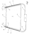
- Fig. 1 shows the broken cut-off rear area
- the figure illustrates a view of the right inner side, which is a mirror image of the broken left inside.
- the illustration is simplified, for example, body internal structures, such as stiffeners and fasteners, not shown, since the representation for the understanding of the invention is not required.
- the illustrated body section 1 has a roof 2, from the side of a B-pillar 3 leads down to a bottom group, not shown. A corresponding B-pillar would be conceivable on the broken-off side of the vehicle.
- the roof 2 merges at its rear edge into a rear window 4. Laterally ends the rear window 4 on a C-pillar, which is located at a distance from the B-pillar 3.
- the C-pillar 5 carries an inner lining 6.
- a rear right side door 7 is hinged to the B pillar in the known manner.
- a rear seat 8 At the height of the rear right side door is a rear seat 8, to which a seat 9 and a rear seat back 11 belong.
- the rear seat surface 9 lies on a base surface 12 which belongs to the floor assembly and in which foot spaces 13 are formed in front of the rear seat surface 9.
- the rear window roller blind 14 shows its partially drawn roller blind 15 and one of the lateral guide rails 16.
- the guide rail 16 starts at a behind the rear seat back eleventh existing hat shelf 17 and runs next to the lateral edge of the window.
- the guide rail is made of plastic and is integrated in the C-pillar 5 lining interior lining.
- the parcel shelf 17 contains a continuous pull-out slot 18 from which the roller blind 15 runs out during extension.
- a winding shaft 19 extends, which is rotatably mounted and on which the roller blind 15 is fastened with one edge.
- the winding shaft 19 is biased by means of a schematically indicated spring motor 21 in the sense of winding the roller blind 15 on the winding shaft 19.
- a coil spring is provided, which is anchored at one end to the body and fixed at the other end in the winding shaft 19.
- the runway 15 has an approximately trapezoidal blank and is provided on its edge remote from the winding shaft 19 edge with a tubular loop. Through the tubular loop leads a pull-out profile or bow 22, in the end pieces 23, 24 are mounted telescopically.
- the end pieces 23, 24 have a neck portion 25 which has a smaller diameter than a guide member 26 adjoining thereto.
- the guide member 26 has the shape of a short cylindrical portion.
- the guide members 26 run in the mutually mirror-image arranged guide rails 16, which are arranged next to the two side edges of the rear window 4 and the clamped shade 15.
- Each guide rail 16 includes a guide groove 27 whose cross-sectional profile is composed of a groove slot 28 and a groove chamber 29.
- the diameter of the circular groove chamber 29 corresponds to the diameter of the guide member 26 while the width of the groove slot 28, which is smaller than the diameter of the circular groove chamber 29, a passage of the neck portion 25 allows.
- each guide rail 16 is coupled via a guide tube 30, 31 with a linear drive 32.
- a cross-sectionally circular push or coupling element 32 In the groove chamber 29 of the right guide rail 16 extends a cross-sectionally circular push or coupling element 32.
- the push or coupling element is largely pressure-resistant and out with the help of the guide rail and the guide tube 31 ausknickêt. In this way, both the pressure force and the tensile force exerted by the linear drive 34 can be transmitted to the relevant guide member 26.
- this is drawn in the drawing with a slight distance to allow the viewer to differentiate between the guide member 26 and thrust member 32, but in fact the two components are tensile and pressure-resistant connected together.
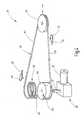
- the structure of the linear drive is shown in Fig. 3 enlarged.
- the linear drive 34 includes two axially parallel rotatably mounted toothed pulleys 35 and 36, with the same effective diameter.
- the toothed belt pulley 35 is mounted so as to be loosely rotatable, while the toothed belt pulley 36 is non-rotatably mounted on an output shaft 37 of a geared motor 38.
- the gear motor 38 has a permanently energized sliding motor 39, which can be optionally supplied via the electrical system of the motor vehicle with electricity to rotate, depending on the polarity, the toothed belt 36 in a clockwise or counterclockwise direction.
- a guide rail 44 which is connected at the end to the guide tube 31 extends.
- the guide rail 44 includes a guide groove 45 which is composed of a groove chamber 46 and a groove slot 47.
- the dimensions of the groove slot 47 and the groove chamber 46 coincide with the dimensions of the groove slot 28 and the groove chamber 29 of the guide rails 16, so that even in the guide rail 44 recognizable end of the push or coupling element 32 is guided ausknickêt and through the slot slot 47 also can not escape to the outside.
- a carriage 48 in which the respective end of the push or coupling element 32 is inserted and riveted with rivets 49 runs. From the carriage 48, a neck portion 51 leads outwardly to the belt 42 and is secured there by means of a screw or rivet 52 which passes through the belt 42.
- a further guide rail 53 which has the same structure as the guide rail 44, so the same reference numerals are used for the individual elements of the guide rail 53, as for the guide rail 44th
- a carriage 54 runs with a neck portion 55.
- the relevant end of the push or coupling element 33 is anchored while the neck portion 55 leads out through the slot slot 47 and by means of a screw or a rivet 56 with the belt rim 43 is connected.
- the two guide rails 44 and 53 not only lie on different sides of the oval formed by the endless toothed belt 41, but they also face in the opposite direction, i. from the upper guide rail 44, the connecting pipe 31 goes to the right, while from the lower guide rail 53, the connecting pipe 30 leads away to the left. As a result, opposing movements with the same stroke can be generated.
- the mode of operation of the arrangement is as follows, whereby the functional description also results in possibly missing dimensioning information.
- Fig. 3 shows the linear actuator 34 also in the retracted position of the roller blind. As can be seen, is located in this position, the carriage 48 adjacent to the free end of the guide rail 44 and thus in the vicinity of the loose-running pulley 35. Analogously, the same applies to the carriage 54, which is also in the vicinity of the free end of the guide rail 53 stands and thus in the vicinity of the driven toothed pulley 36th
- the geared motor 38 is set in motion by switching on the supply voltage with the corresponding direction of rotation, ie, with reference to the illustration in FIG. 3 such that the driven toothed belt pulley 36 rotates in the clockwise direction
- the belt drum 42 pulls the carriage 48.
- Fig. 3 from left to right, ie from the open end of the guide rail 44 in the direction of the connecting tube 31.
- the thus driven toothed belt 41 tows synchronously with the same stroke the carriage 44, based on Fig. 3, from the right Left.
- the carriage 54 moves with the immovably connected push or coupling element 33 in the direction of the loosely running toothed belt pulley 35.
- the distance of the axes of rotation of the two pulleys 35 and 36 must be long enough.
- the anchoring of neither the carriage 48 to the toothed belt 41, nor the anchoring of the carriage 54 on the toothed belt 51 with one of the two pulleys 35, 36 may collide.
- the carriage 48 is next to the pulley 36, while the carriage 54 of the pulley 35 is adjacent.
- the gear motor 38 is turned on with the opposite direction of rotation, so that now on the belt 43 a tensile force on the two carriages 48 and 54 is transmitted.
- the push or coupling members 32, 33 are retracted from the guide rails 16.
- the roller blind 15 is wound on the winding shaft 19 by the spring motor 21 accordingly.
- the arrangement shown has the significant advantage that the two push or coupling elements 32, 33 are completely smooth on its outer peripheral surface. As a result, no loud noises can occur when the two push or coupling members 32, 33 run during retraction or extension over any edges, due to the connection between the guide tubes 30, 31 with the guide rails 16 and 44 and 53 are unavoidable.
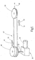
- Fig. 4 shows an alternative embodiment for the linear drive 34.
- the main difference is the use of a rope 58 instead of the toothed belt 41.
- Fig. 4 is limited to the representation of the drive for the cable 58, because the arrangement of the guide rail 54 and 53 is similar, as shown in Fig. 3.
- a Seilumlenkicrobial 59 is present, to the axially parallel a cable drive pulley 61 is mounted.
- the cable drive pulley 61 is rotatably mounted on the output shaft 37 of the geared motor 38 has the same structure, as has already been explained in connection with FIG.
- one end of the cable 58 is fixed in a mounting slot. It leads from the cable drive pulley 61 to the Seilumlenkicrobial 59 around them back to the cable drive pulley 61.
- the cable 68 forms a winding storage 64th Mit In other words, the rope 58 lies between the inlet point and anchoring in several turns around the pulley 61.
- the length of the rope thus stored corresponds at least to the axial distance between the cable guide pulley 59 and the cable drive pulley 61.
- the respective slide 48 or 54 is connected to the two cable guides 61 and 62, as indicated in FIG. 4. That the two Seiltrumme 61, 62 in the same manner as the Bandtrumme 42, 43 move in opposite directions, in the corresponding attachment of the two carriages 48, 54, the required opposing movement of the thrust and coupling elements 32, 33 are generated, as detailed above is explained.
- the drive of FIG. 4 is slip-free.
- the rope consists of an aramid thread, for example Kevlar. It can also be a monofilament.
- Fig. 5 shows in a highly schematic form such a drive.
- a closed rope ring 67 is used instead of the rope 58 with the two open ends anchored to the rope drive pulley 60.
- the cable ring simply lies around the cable guide pulley 59 while forming one or two complete turns on the cable drive pulley 60.
- the cable drive pulley 60 thus acts in a similar way to a winch, so that it is possible in turn to set the carriages 48 and 54 fixed to the two cable troughs 61 and 62.
- the pulley 59 is slidably mounted in the direction parallel to the double arrow 68 to keep the cable ring 67 constantly under a sufficient bias.
- the invention is explained in connection with a rear window roller blind with two guide rails.
- the illustrated drive concept with linear drive and smooth push and coupling elements can also be used in side windows, since the position of the guide rails within the vehicle of the inventive idea is independent.
- the drive concept is also related Can be used with roof windows of vehicles and / or side or front windows.
- a window blind for motor vehicles has guide rails next to the roller blind. Run in the guide rails, guided kink-proof, pushing or pressing members, which have a smooth outer surface.
- the drive of these push or push members is done by means of a linear drive, which is constructed with belts or ropes.
Landscapes
- Engineering & Computer Science (AREA)
- Mechanical Engineering (AREA)
- Operating, Guiding And Securing Of Roll- Type Closing Members (AREA)
- Transmission Devices (AREA)
Applications Claiming Priority (1)
| Application Number | Priority Date | Filing Date | Title |
|---|---|---|---|
| DE102005036318A DE102005036318A1 (de) | 2005-07-29 | 2005-07-29 | Fensterrollo mit glatten Schubgliedern |
Publications (2)
| Publication Number | Publication Date |
|---|---|
| EP1747923A2 true EP1747923A2 (fr) | 2007-01-31 |
| EP1747923A3 EP1747923A3 (fr) | 2009-07-01 |
Family
ID=37209341
Family Applications (1)
| Application Number | Title | Priority Date | Filing Date |
|---|---|---|---|
| EP06013324A Withdrawn EP1747923A3 (fr) | 2005-07-29 | 2006-06-28 | Store à enrouler de fenêtre avec des pousées non-profilées |
Country Status (6)
| Country | Link |
|---|---|
| US (1) | US20070023152A1 (fr) |
| EP (1) | EP1747923A3 (fr) |
| JP (1) | JP2007039026A (fr) |
| KR (1) | KR20070014982A (fr) |
| CN (1) | CN1936260B (fr) |
| DE (1) | DE102005036318A1 (fr) |
Cited By (3)
| Publication number | Priority date | Publication date | Assignee | Title |
|---|---|---|---|---|
| EP1886856A1 (fr) * | 2006-08-10 | 2008-02-13 | Toyota Boshoku Kabushiki Kaisya | Appareil de pare-soleil |
| EP2014493A3 (fr) * | 2007-07-11 | 2010-12-22 | BOS GmbH & Co. KG | Guidage latéral pour store d'occultation et store d'occultation pour véhicule automobile |
| US20160325687A1 (en) * | 2015-05-08 | 2016-11-10 | Herbert Walter | Protective device for a vehicle interior |
Families Citing this family (11)
| Publication number | Priority date | Publication date | Assignee | Title |
|---|---|---|---|---|
| DE102007012281A1 (de) * | 2007-03-09 | 2008-09-11 | Bos Gmbh & Co. Kg | Automatisch betätigbares Seitenfensterrollo |
| DE102007012259A1 (de) * | 2007-03-12 | 2008-09-18 | Bos Gmbh & Co. Kg | Sonnenschutzrollo für Kraftfahrzeuge |
| DE102007016154A1 (de) * | 2007-03-21 | 2008-09-25 | Bos Gmbh & Co. Kg | Seitenfensterrollo mit anscharniertem Zugstab und rechteckigem Tragstab |
| DE102007054694A1 (de) * | 2007-11-14 | 2009-05-20 | Bos Gmbh & Co. Kg | Rolloanordnung mit verminderter Reibung in den Antriebsgabeln |
| CN102499569B (zh) * | 2011-09-28 | 2015-06-17 | 宁波杜亚机电技术有限公司 | 一种电动天棚帘 |
| JP6629049B2 (ja) * | 2015-11-18 | 2020-01-15 | 芦森工業株式会社 | 車両用シェード装置 |
| DE102018205782B4 (de) * | 2018-04-17 | 2024-08-14 | Festo Se & Co. Kg | Verwendung einer Antriebseinrichtung zur Vereinzelung von in einer Fördererebene zu fördernden Gegenständen |
| DE102018205781B4 (de) * | 2018-04-17 | 2024-08-14 | Festo Se & Co. Kg | Antriebseinrichtung |
| US11297725B2 (en) | 2018-09-11 | 2022-04-05 | Lg Electronics Inc. | Display device |
| CN109532684A (zh) * | 2018-11-22 | 2019-03-29 | 大乘汽车有限公司 | 一种遮物帘 |
| DE102022116261B3 (de) | 2022-06-29 | 2023-12-14 | Röchling Automotive SE | Umlenkrolle mit beidseits erleichterter Seilmontage |
Citations (3)
| Publication number | Priority date | Publication date | Assignee | Title |
|---|---|---|---|---|
| DE10040624A1 (de) | 2000-08-16 | 2002-03-07 | Bos Gmbh | Fahrzeug mit Sonnenschutzrollo im Dach |
| DE10057764A1 (de) | 2000-11-22 | 2002-06-06 | Bos Gmbh | Fensterrollo mit variabler Abschattungswirkung |
| DE20309690U1 (de) | 2003-06-24 | 2003-09-11 | Kuhlemann, Horst, 32825 Blomberg | Sonnenschutzrollo, insbesondere für Kraftfahrzeugfenster |
Family Cites Families (16)
| Publication number | Priority date | Publication date | Assignee | Title |
|---|---|---|---|---|
| US1232439A (en) * | 1917-01-30 | 1917-07-03 | Elevator Efficiency Appliance Co Inc | Silencer and connecting medium for elevator-doors. |
| US1758220A (en) * | 1928-04-21 | 1930-05-13 | Currivan John Francis | Window-curtain control |
| US2641135A (en) * | 1950-08-15 | 1953-06-09 | Pioneer Specialty Company | Actuating means for antennas and the like |
| US3809366A (en) * | 1973-04-26 | 1974-05-07 | S Crees | Apparatus for drawing conductor wires through conduits |
| DE3415930A1 (de) * | 1984-04-28 | 1985-10-31 | Baumeister & Ostler, 7307 Aichwald | Kraftfahrzeugfensterrollo |
| DE3612165A1 (de) * | 1986-04-11 | 1987-10-22 | Baumeister & Ostler | Fuehrungsloses fensterrollo, insbesondere fuer kraftfahrzeuge |
| US4944465A (en) * | 1989-05-11 | 1990-07-31 | Levine Aaron J | Spring driving and winding machine |
| DE4239962C1 (de) * | 1992-11-27 | 1994-07-21 | Erich Doering | Riementrieb, insbesondere für Torantriebe |
| FR2726060B1 (fr) * | 1994-10-20 | 1996-11-29 | Hutchinson | Courroie de transmission de puissance |
| CN2270644Y (zh) * | 1996-06-27 | 1997-12-17 | 林永清 | 汽车电动窗帘装置 |
| US6119401A (en) * | 1998-07-31 | 2000-09-19 | Hi-Lex Corporation | Dual-slider window regulator with three flexible, inextensible drive members |
| DE10005951A1 (de) * | 2000-02-09 | 2001-08-16 | Bos Gmbh | Heckfensterrollo |
| DE10052042A1 (de) * | 2000-10-20 | 2002-05-16 | Bos Gmbh | Antriebssystem für rollbare Abdeckeinrichtungen von Kraftfahrzeugen |
| DE10057762A1 (de) * | 2000-11-22 | 2002-06-06 | Bos Gmbh | Fensterrollo mit Ausgleich gegen Verzug |
| KR100425005B1 (ko) * | 2001-10-10 | 2004-03-30 | 코리아에프티 주식회사 | 자동차의 차양장치 |
| DE10248591B4 (de) * | 2002-10-17 | 2006-04-20 | Bos Gmbh & Co. Kg | Fensterrollo mit Deckel auf dem Auszugschlitz |
-
2005
- 2005-07-29 DE DE102005036318A patent/DE102005036318A1/de not_active Withdrawn
-
2006
- 2006-06-28 EP EP06013324A patent/EP1747923A3/fr not_active Withdrawn
- 2006-07-18 US US11/488,222 patent/US20070023152A1/en not_active Abandoned
- 2006-07-21 KR KR1020060068579A patent/KR20070014982A/ko not_active Withdrawn
- 2006-07-25 JP JP2006202081A patent/JP2007039026A/ja active Pending
- 2006-07-28 CN CN2006101081957A patent/CN1936260B/zh not_active Expired - Fee Related
Patent Citations (3)
| Publication number | Priority date | Publication date | Assignee | Title |
|---|---|---|---|---|
| DE10040624A1 (de) | 2000-08-16 | 2002-03-07 | Bos Gmbh | Fahrzeug mit Sonnenschutzrollo im Dach |
| DE10057764A1 (de) | 2000-11-22 | 2002-06-06 | Bos Gmbh | Fensterrollo mit variabler Abschattungswirkung |
| DE20309690U1 (de) | 2003-06-24 | 2003-09-11 | Kuhlemann, Horst, 32825 Blomberg | Sonnenschutzrollo, insbesondere für Kraftfahrzeugfenster |
Cited By (6)
| Publication number | Priority date | Publication date | Assignee | Title |
|---|---|---|---|---|
| EP1886856A1 (fr) * | 2006-08-10 | 2008-02-13 | Toyota Boshoku Kabushiki Kaisya | Appareil de pare-soleil |
| US7717157B2 (en) | 2006-08-10 | 2010-05-18 | Toyota Boshoku Kabushiki Kaisha | Sun shade apparatus |
| EP2014493A3 (fr) * | 2007-07-11 | 2010-12-22 | BOS GmbH & Co. KG | Guidage latéral pour store d'occultation et store d'occultation pour véhicule automobile |
| US8800635B2 (en) | 2007-07-11 | 2014-08-12 | Bos Gmbh & Co. Kg | Lateral guide for shading roller blind, and shading roller blind for motor vehicles |
| US20160325687A1 (en) * | 2015-05-08 | 2016-11-10 | Herbert Walter | Protective device for a vehicle interior |
| US9725044B2 (en) * | 2015-05-08 | 2017-08-08 | Bos Gmbh & Co. Kg | Protective device for a vehicle interior |
Also Published As
| Publication number | Publication date |
|---|---|
| US20070023152A1 (en) | 2007-02-01 |
| DE102005036318A1 (de) | 2007-02-01 |
| JP2007039026A (ja) | 2007-02-15 |
| CN1936260A (zh) | 2007-03-28 |
| CN1936260B (zh) | 2011-12-28 |
| KR20070014982A (ko) | 2007-02-01 |
| EP1747923A3 (fr) | 2009-07-01 |
Similar Documents
| Publication | Publication Date | Title |
|---|---|---|
| DE10057763C2 (de) | Doppelrollo mit vereinfachtem Antrieb | |
| EP1905630B1 (fr) | Store de fenêtre actionné manuellement | |
| DE10057760B4 (de) | Fensterrollo mit Zentriereinrichtung für den Zugstab | |
| EP1149718B1 (fr) | Store pour fenêtre latérale avec obturateur de fente | |
| EP1800923B1 (fr) | Store de fenêtre latéral doté d'une barre portante | |
| EP1666291B1 (fr) | Store à enrouler de fenêtre avec montage simplifié | |
| EP1533158B1 (fr) | Système de store à enrouleur pour vitres latérals pourvu d'un pièce de contour de vitre | |
| EP1967401A2 (fr) | Store de fenêtre latérale actionné de manière automatique | |
| DE10151872A1 (de) | Geteiltes Fensterrollo für Kraftfahrzeuge | |
| EP1209013A2 (fr) | Vitre avec store à enrouleur attaché | |
| DE102007012259A1 (de) | Sonnenschutzrollo für Kraftfahrzeuge | |
| EP1794012A1 (fr) | Systeme de store pour vehicule automobile | |
| DE3415930A1 (de) | Kraftfahrzeugfensterrollo | |
| DE102005036318A1 (de) | Fensterrollo mit glatten Schubgliedern | |
| EP1619057A2 (fr) | Agencement de store pare-soleil pour vitre latérale | |
| DE102007039255A1 (de) | Heckscheibenrollo mit Winkeltragschiene | |
| EP1626152A1 (fr) | Protection solaire pour un toit vitré | |
| EP1738942B1 (fr) | Store à enrouleur pour véhicule automobile muni d'une butée de contact fixée rigidement sur un actionneur | |
| DE202007008186U1 (de) | Sonnenschutzrollo für Kraftfahrzeuge | |
| DE202005020691U1 (de) | Fensterrollo mit glatten Schubgliedern | |
| DE102019106300B4 (de) | Antriebsvorrichtung für den Antrieb einer Rollovorrichtung eines rahmenlosen Fahrzeugfensters | |
| DE202007008178U1 (de) | Seitenfensterrollo | |
| DE102016213199A1 (de) | Beschattungsvorrichtung für eine Seitenscheibe eines Kraftfahrzeugs | |
| DE202006017842U1 (de) | Rollo mit hinterschneidungsfreier Führungsschiene | |
| DE102024105426A1 (de) | Rolloanordnung mit zwei Rollobahnen |
Legal Events
| Date | Code | Title | Description |
|---|---|---|---|
| PUAI | Public reference made under article 153(3) epc to a published international application that has entered the european phase |
Free format text: ORIGINAL CODE: 0009012 |
|
| AK | Designated contracting states |
Kind code of ref document: A2 Designated state(s): AT BE BG CH CY CZ DE DK EE ES FI FR GB GR HU IE IS IT LI LT LU LV MC NL PL PT RO SE SI SK TR |
|
| AX | Request for extension of the european patent |
Extension state: AL BA HR MK YU |
|
| PUAL | Search report despatched |
Free format text: ORIGINAL CODE: 0009013 |
|
| AK | Designated contracting states |
Kind code of ref document: A3 Designated state(s): AT BE BG CH CY CZ DE DK EE ES FI FR GB GR HU IE IS IT LI LT LU LV MC NL PL PT RO SE SI SK TR |
|
| AX | Request for extension of the european patent |
Extension state: AL BA HR MK RS |
|
| 17P | Request for examination filed |
Effective date: 20090723 |
|
| 17Q | First examination report despatched |
Effective date: 20090819 |
|
| AKX | Designation fees paid |
Designated state(s): DE FR SE |
|
| STAA | Information on the status of an ep patent application or granted ep patent |
Free format text: STATUS: THE APPLICATION IS DEEMED TO BE WITHDRAWN |
|
| 18D | Application deemed to be withdrawn |
Effective date: 20160713 |