EP1748005B1 - Rayonnage à palettes avec convoyeur - Google Patents
Rayonnage à palettes avec convoyeur Download PDFInfo
- Publication number
- EP1748005B1 EP1748005B1 EP06116884A EP06116884A EP1748005B1 EP 1748005 B1 EP1748005 B1 EP 1748005B1 EP 06116884 A EP06116884 A EP 06116884A EP 06116884 A EP06116884 A EP 06116884A EP 1748005 B1 EP1748005 B1 EP 1748005B1
- Authority
- EP
- European Patent Office
- Prior art keywords
- pallets
- push
- conveyor frame
- pallet
- tracks
- Prior art date
- Legal status (The legal status is an assumption and is not a legal conclusion. Google has not performed a legal analysis and makes no representation as to the accuracy of the status listed.)
- Not-in-force
Links
- 239000000463 material Substances 0.000 claims abstract description 11
- 230000000149 penetrating effect Effects 0.000 claims abstract description 4
- 230000035515 penetration Effects 0.000 claims abstract description 4
- 230000000694 effects Effects 0.000 claims abstract description 3
- 239000002023 wood Substances 0.000 claims description 5
- 239000002184 metal Substances 0.000 claims description 4
- 238000005452 bending Methods 0.000 claims description 3
- 229920003002 synthetic resin Polymers 0.000 claims description 3
- 239000000057 synthetic resin Substances 0.000 claims description 3
- 238000007665 sagging Methods 0.000 abstract 1
- 238000010276 construction Methods 0.000 description 16
- 229910000831 Steel Inorganic materials 0.000 description 2
- 230000002349 favourable effect Effects 0.000 description 2
- 239000012634 fragment Substances 0.000 description 2
- 238000000926 separation method Methods 0.000 description 2
- 239000011122 softwood Substances 0.000 description 2
- 229910001220 stainless steel Inorganic materials 0.000 description 2
- 239000010935 stainless steel Substances 0.000 description 2
- 239000010959 steel Substances 0.000 description 2
- 229910000737 Duralumin Inorganic materials 0.000 description 1
- 241000219094 Vitaceae Species 0.000 description 1
- 235000020971 citrus fruits Nutrition 0.000 description 1
- 230000003750 conditioning effect Effects 0.000 description 1
- 230000001419 dependent effect Effects 0.000 description 1
- 235000013399 edible fruits Nutrition 0.000 description 1
- 239000000835 fiber Substances 0.000 description 1
- 239000000945 filler Substances 0.000 description 1
- 235000021021 grapes Nutrition 0.000 description 1
- 238000012986 modification Methods 0.000 description 1
- 230000004048 modification Effects 0.000 description 1
- 238000007747 plating Methods 0.000 description 1
- 230000000284 resting effect Effects 0.000 description 1
- 230000000717 retained effect Effects 0.000 description 1
- 238000005096 rolling process Methods 0.000 description 1
- 125000006850 spacer group Chemical group 0.000 description 1
- 229920002994 synthetic fiber Polymers 0.000 description 1
- 235000013311 vegetables Nutrition 0.000 description 1
Images


Classifications
-
- B—PERFORMING OPERATIONS; TRANSPORTING
- B65—CONVEYING; PACKING; STORING; HANDLING THIN OR FILAMENTARY MATERIAL
- B65G—TRANSPORT OR STORAGE DEVICES, e.g. CONVEYORS FOR LOADING OR TIPPING, SHOP CONVEYOR SYSTEMS OR PNEUMATIC TUBE CONVEYORS
- B65G19/00—Conveyors comprising an impeller or a series of impellers carried by an endless traction element and arranged to move articles or materials over a supporting surface or underlying material, e.g. endless scraper conveyors
- B65G19/02—Conveyors comprising an impeller or a series of impellers carried by an endless traction element and arranged to move articles or materials over a supporting surface or underlying material, e.g. endless scraper conveyors for articles, e.g. for containers
-
- B—PERFORMING OPERATIONS; TRANSPORTING
- B65—CONVEYING; PACKING; STORING; HANDLING THIN OR FILAMENTARY MATERIAL
- B65G—TRANSPORT OR STORAGE DEVICES, e.g. CONVEYORS FOR LOADING OR TIPPING, SHOP CONVEYOR SYSTEMS OR PNEUMATIC TUBE CONVEYORS
- B65G1/00—Storing articles, individually or in orderly arrangement, in warehouses or magazines
- B65G1/02—Storage devices
- B65G1/04—Storage devices mechanical
- B65G1/06—Storage devices mechanical with means for presenting articles for removal at predetermined position or level
-
- B—PERFORMING OPERATIONS; TRANSPORTING
- B65—CONVEYING; PACKING; STORING; HANDLING THIN OR FILAMENTARY MATERIAL
- B65G—TRANSPORT OR STORAGE DEVICES, e.g. CONVEYORS FOR LOADING OR TIPPING, SHOP CONVEYOR SYSTEMS OR PNEUMATIC TUBE CONVEYORS
- B65G2201/00—Indexing codes relating to handling devices, e.g. conveyors, characterised by the type of product or load being conveyed or handled
- B65G2201/02—Articles
- B65G2201/0267—Pallets
Definitions
- the invention relates to a push-through conveyor frame for accommodating pallets in pallet positions which are organized along tracks having a track's axis and the pallets having two outer sides in a direction transverse to the track's axis, wherein two tracks supports the accommodated pallets adjacent the outer sides thereof, all this as further defined in the opening section of claim 1 and as disclosed in document CH 60 5350 A .
- the use of such pallets renders it possible to organize the transport, storage, conditioning, etc. of various products in a modular manner. Many pallet dimensions have been defined for a variety of products. The quality of the pallets is often not high (especially in the case of comparatively inexpensive products such as vegetables and fruit). Often they are throw-away pallets of low-grade wood which are used only once.
- the pallets are introduced one by one into the frame mentioned above by means of a forklift truck or the like. This implies that the previous pallet(s) in the track has (have) to move along upon the introduction of the next pallet such that their relative movements remain negligibly small.
- the present invention is thus characterized in that said drive means comprise a continuous chain which is present below the pallet positions in an intermediate position between the two tracks and which is provided with fixation points capable of penetrating the pallet material in upward direction and thus are counteracting movements of consecutive pallets relative to one another, while the two track's that support the accommodated pallets at the outer sides thereof are free of such fixation points, in that said chain comprises one or several rollers per link, which roller or rollers is or are provided on a common shaft in said transverse direction, in that a supporting track is provided for said link rollers for the purpose of bearing part of the pallet weight and in that grooves are provided in axial direction of the track for the shafts of said link rollers along a return track so as to guide the links along a substantially straight line.
- said drive means comprise a continuous chain which is present below the pallet positions in an intermediate position between the two tracks and which is provided with fixation points capable of penetrating the pallet material in upward direction and thus are counteracting movements of consecutive pallets relative to one another, while the
- Such a passively operating fixation is particularly effective for pallets made of soft wood and similar materials. No driving force is required in many cases other than the force of the fork-lift truck which is necessary anyway for introducing and removing the pallets.
- the combination of a continuous chain with a passive end support for the pallets is inexpensive and is found to be practically achievable with a sufficiently low friction.
- Such a comparatively open construction renders it possible for broken-off fragments of the pallets to drop through the respective components of the frame without causing an obstruction of the drive.
- the separation of the drive function (intermediate / central position) and the support function (adjacent the outer side / at the end) is favorable in many respects: it is found that the pallets can be better transported, and breaking off of pallet fragments less often leads to an interruption of their movement.
- the support function finally, can be realized in a comparatively inexpensive manner owing to this separation.
- a push back storage assembly is known from US 5,915,516 B1, published June 29, 1999 .
- pallets are supported at the outer sides thereof by tracks containing roller chains that are provided with jagged projections on top in order to improve the non-positive connection between the roller chains and the pallet received thereon.
- said drive means comprise only one such chain, which extends substantially along the length of the track.
- This is found to be an inexpensive solution of a satisfactory quality.
- the support function adjacent the outer sides may then be advantageously fulfilled by roller tracks, preferably in the form of roller chains. It is furthermore conceivable, for example, that pallets of a synthetic material are supported adjacent their outer sides by metal strips, which then at the same time act as sliding surfaces.
- said penetration is activated by the weight of a loaded pallet and/or the bending movement thereof.
- said chain is located substantially centrally between said outer sides.
- This combines well with the construction of most pallets, which usually have 3 x 3 supports between the deck and the bottom laths below them. It is also well suited to the pallets especially if a central support lath thereof is located above the chain and in the direction of the track.
- the expression 'substantially centrally' means that the chain is out of center by not more than approximately half the width of the bottom lath. This may amount to a tolerance of, for example, +/- 10 to 15 cm with respect to the center.
- said chain lies recessed in a supporting beam.
- the beam may be, for example, of wood, synthetic resin, or metal. Wood is useful in e.g. refrigerated compartments because of its low heat capacity and is easy to work.
- said chain is provided over substantially its entire length with fixation points arranged on each chain link.
- a FIFO (First In First Out) arrangement is made possible thereby, with inlet and outlet at mutually opposed ends of the track.
- LIFO Laser In First Out
- said chain is built up from roller-type link modules consecutively arranged in transverse direction for each chain link, while said fixation points are positioned between consecutive link modules and at the ends thereof each time.
- the invention also relates to an assembly kit as claimed in claim 12 suitable for constructing a push-through conveyor frame as claimed in claim 1 in combination with an assembly provided with stationary components.
- the stationary components of the assembly may be present already, in which case the application of the invention constitutes an improvement.
- the assembly kit may comprise, for example, a continuous chain, or one that can be made continuous, with fixation points, possibly two supporting conveyor tracks to be mounted laterally, and furthermore possibly a suitable selection of mounting and adjustment materials. Further advantageous aspects of the invention are recited in the dependent claims.
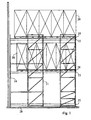
- Fig. 1 gives a general picture of a push-through conveyor frame viewed transversely to the track direction.
- the expression 'push-through' here denotes that, when a new pallet is placed in a track, all pallets already present in this track must be shifted along by one position. It is possible in principle both that pallets are removed at the input side (LIFO) and that pallets are removed at the other side (FIFO). It is assumed in the ensuing description that the former is the case, but those skilled in the art will immediately perceive the feasibility of the alternative configuration and its possibilities.
- the frame as shown has three levels, of which the upper two are occupied by filled pallets 20 of two mutually different dimensions, the pallets proper being referenced '28'.
- Reference numeral 22 indicates the pallet tracks, 21 the general construction, 26 the floor, and 24 a closed rear wall.
- the various standard dimensions, weights to be supported, and subassemblies of the pallets may be derived from the general literature.
- the pallet is first moved to straight in front of the track at the correct height by means of a fork-lift truck.
- the pallet is then introduced in that it is driven forward, during which the central support lath is kept in central position.
- the forks of the fork-lift truck are horizontal during this, and the newly inserted pallet makes contact with the previously inserted pallet, and so on between all pallets present. The latter are thus all shifted one position further.
- Once the new pallet has been inserted sufficiently far, it is lowered until it anchors itself in the chain with teeth.
- the fork-lift truck can then be backed away.
- the fork-lift truck is again centrally positioned in front of the track, and the forks are horizontally inserted into the free spaces in the substructure of the pallet.
- the forks are not allowed to touch the second pallet in the track here.
- the vertical fork lift shaft (along which the connection points of the forks can move up and down) is tilted forward and the forks are slightly lifted, so that the outermost (front) edge of the pallet is slightly lifted, but the rest of the pallet still rests on the drive chain.
- the fork-lift truck is now slowly driven back, whereby the pallet is dragged along, during which the inner (rear) portion of the pallet still rests on the fixation points, so that the drive chain is taken along in the movement.
- the other pallets will thus also move along with the drive chain.
- the shaft of the fork-lift truck can be tilted back again, and the pallet becomes detached from the chain track.
- the pallet can then be removed.
- An optional slope in the drive track towards the delivery position may make it even easier for the remaining pallets to move along. This arrangement, however, is not always necessary. The slope will be in the other (exit) direction in the case of a FIFO construction.
- Fig. 2 presents a general view of a push-through conveyor frame taken in the direction of the track, again with filled pallets 20 with pallet constructions 28, conveyor tracks 22, a general construction 21, and a floor 26.
- the number of pallet tracks next to one another (two in this case) and above one another (three in this case) as well as the number of pallets that can be placed in each track may be freely chosen in principle.
- Fig. 3 illustrates the general configuration of a push-through conveyor frame according to the invention, being a further development of Fig. 2 .
- the construction 21 comprises besides vertical support poles also horizontal supports 27 for the tracks.
- Two outer conveyor tracks 30, 32 (provided with rollers in this embodiment, cf. Fig. 4b ) are provided for each track so as to provide a suitable outer support for the pallets.
- guide means are shown, in the form of a beam 34 provided with a continuous chain, which will be elaborated in detail in Fig. 4a .
- the not inconsiderable filling weight of the pallets and their comparatively low-grade construction will cause the pallets to sag somewhat at the area of the continuous chain. This is used to advantage in the invention.
- the relative levels of the elements 30, 32, 34 may be adjusted in a known manner by means of fillers or the like.
- Figs. 4a and 4b show components of the push-through conveyor frame of Fig. 3 in more detail.
- Fig. 4a shows the conveyor tracks 30, 32. These each consist of a beam of some suitable material, such as steel, stainless steel, duraluminum, or possibly wood, the latter e.g. for use in spaces with temperature control such as cold storage compartments.
- a groove 60 is provided in the beam, in which groove rollers 62 can support the pallets while rolling.
- the shaft 64 of each roller is fixed in vertical direction, for example by means of a plain bearing, cf. Fig. 6 .
- the rollers are preferably incorporated in a chain of which each link comprises a roller module and which is kept taut by respective connections fixed to the ends of the beam: i.e. this chain does not move.
- the roller modules further reduce the friction for the pallets resting thereon.
- Fig. 4b shows the arrangement of the beam 34 provided with the drive chain of Fig. 3 in more detail.
- the active side faces upwards in the Figure, which also shows roller-type link modules 42, 44 and a shaft 40.
- the chain is returned at the lower side of the beam 34.
- two grooves 66, 68 for the shafts 40 are provided therein. Returning gearwheels at the beginning and end of the central beam 34 have not been shown for simplicity's sake.
- the recessed portions 50 and 70 may be made from a suitable material, such as synthetic resin.
- each link of the chain comprises two roller-type link modules 42, 44 which have their bearings on a shaft 40.
- the chain itself is formed by links 46 made from metal plating, for example stainless steel.
- Spacer links 48 are arranged between the link rollers and the links 46 each time, such that the link types 46 and 48 occur in alternation in longitudinal direction, cf. Fig. 5c .
- the chain can operate in two modes. First, it is possible for the chain to be uniformly coupled in a closed loop. This is necessary, for example, if the supply and delivery of the pallets take place at mutually opposed ends of the track.
- the links 46 are provided with projecting fixation points capable of penetrating the pallet material, whereby the pallets are substantially fixedly retained relative to the chain.
- the links 48 do not carry these fixation points, but this is not a limitation.
- these links are of single construction at the outer sides but of double construction in the center. The latter construction serves to realize a greater strength counteracting bending of the fixation points.
- the distance between consecutive teeth is 15 mm and their height above the shaft 20 mm.
- the teeth may project 15 mm from the shaft in many embodiments.
- Alternative dimensions are also feasible, as is a different tooth shape, for example a different apex angle and/or tooth outline. A comparatively great tooth dimension and spacing will be favorable in particular for a coarse-fiber pallet material.
- Fig. 5b further shows a supporting conveyor track 50 for supporting the link rollers 42, 44 and thus bearing part of the pallet weight.
- Fig. 5a shows some link rollers in cross-section, others in elevation.
- Fig. 6 shows details of the outer conveyor tracks (accommodated in the beams 30, 32 of Fig. 4a ). In fact, these constitute simple embodiments of the construction of Fig. 5 with shafts 50, roller link modules 52, and alternating inner and outer links 54, 56, and obviously without teeth. The fixation at the ends of the conveyor tracks has not been shown for simplicity's sake.
- a supporting element 50 similar to the component referenced 50 in Figs. 4b , 5b may again be provided here.
Landscapes
- Engineering & Computer Science (AREA)
- Mechanical Engineering (AREA)
- Chain Conveyers (AREA)
- Warehouses Or Storage Devices (AREA)
- Stacking Of Articles And Auxiliary Devices (AREA)
- Sheets, Magazines, And Separation Thereof (AREA)
- Intermediate Stations On Conveyors (AREA)
Claims (12)
- Châssis de convoyeur à poussée pour recevoir des palettes (20, 28) d'un matériau de palette dans des positions de palette qui sont organisées le long de voies (30, 32) présentant un axe de voie et les palettes (20, 28) ont deux côtés extérieurs dans un sens transversal à l'axe de la voie, dans lequel deux voies (30, 32) soutiennent les palettes reçues dans le voisinage des deux côtés extérieurs de celles-ci et dans lequel ledit châssis de convoyeur à poussée est en outre muni d'un moyen d'entraînement (34) pour égaliser mutuellement les mouvements des palettes (20, 28) dans au moins un des sens de mouvement des palettes le long des voies,
caractérisé en ce que lesdits moyens d'entraînement (34, 40-48) comprennent une chaine continue (40-48) qui est présente sous les positions de palette dans une position intermédiaire entre les deux voies (30, 32) et qui est munie de points de fixation (46) qui sont capables de pénétrer le matériau de palette dans un sens vers le haut et agissent ainsi contre les mouvements des palettes (20, 28) consécutives l'une par rapport à l'autre, alors que les deux voies (30, 32) qui soutiennent les palettes reçues sur les côtés extérieurs de celles-ci sont exemptes de tels points de fixation, dans lequel ladite chaîne comprend un ou plusieurs rouleaux (42, 44) par lien, lequel ou lesquels rouleau(x) est ou sont muni(s) d'une tige (40) commune dans ledit sens transversal, dans lequel une voie de soutien (50) est prévue pour lesdits rouleaux de lien afin de supporter une partie du poids de la palette et dans laquelle des rainures (66, 68) sont prévues dans le sens axial de la voie pour les tiges (40) desdits rouleaux de lien le long d'une voie de retour de façon à guider les liens le long d'une ligne essentiellement droite. - Châssis de convoyeur à poussée selon la revendication 1, dans lequel ledit moyen d'entraînement (34) comprend une seule telle chaîne (40-48) qui s'étend essentiellement le long de la longueur des voies (30, 32).
- Châssis de convoyeur à poussée selon la revendication 1, dans lequel l'effet de pénétration est activé par le poids d'une palette chargée (20, 28) et/ou le mouvement de courbure de celle-ci.
- Châssis de convoyeur à poussée selon la revendication 1, dans lequel ladite chaîne (40-48) est située essentiellement centralement entre lesdits côtés extérieurs des palettes (20, 28).
- Châssis de convoyeur à poussée selon la revendication 1, dans lequel ladite chaîne (40-48) est reçue dans une poutre de support (34).
- Châssis de convoyeur à poussée selon la revendication 5, dans lequel ladite poutre de support (34) est essentiellement construite en bois, en résine synthétique ou en métal.
- Châssis de convoyeur à poussée selon la revendication 1, dans lequel ladite chaîne (40-48) est munie sur essentiellement toute sa longueur de points de fixation (46) agencés sur chaque lien de chaîne.
- Châssis de convoyeur à poussée selon la revendication 1, dans lequel chaque lien de ladite chaîne est constitué de modules de liens (42, 44) agencés de manière consécutive dans le sens transversal à la voie, alors que lesdits points de fixation (46) sont placés entre des modules de lien consécutifs ainsi que sur les extrémités de ceux-ci à chaque fois.
- Châssis de convoyeur à poussée selon la revendication 1, dans lequel les deux voies (30, 32) sont munies de rouleaux (62, 64) pour soutenir les côtés extérieurs des palettes le long des voies de palette.
- Châssis de convoyeur à poussée selon la revendication 9, dans lequel lesdites voies de rouleau (30, 32) sont construites comme des chaînes à rouleau.
- Châssis de convoyeur à poussée selon la revendication 1, dans lequel lesdits moyens d'entraînement (34, 40-48) sont agencés de manière à avoir un angle en pente vers une position d'alimentation et/ou d'alimentation du châssis de convoyeur à poussée.
- Kit d'assemblage convenant à la construction d'un châssis de convoyeur à poussée selon la revendication 1 en combinaison avec un assemblage muni de composants fixes.
Applications Claiming Priority (1)
| Application Number | Priority Date | Filing Date | Title |
|---|---|---|---|
| NL1029601A NL1029601C1 (nl) | 2005-07-25 | 2005-07-25 | Doorschuifstelling voor pallets en bouwpakket voor een dergelijke doorschuifstelling. |
Publications (2)
| Publication Number | Publication Date |
|---|---|
| EP1748005A1 EP1748005A1 (fr) | 2007-01-31 |
| EP1748005B1 true EP1748005B1 (fr) | 2010-09-22 |
Family
ID=37336136
Family Applications (1)
| Application Number | Title | Priority Date | Filing Date |
|---|---|---|---|
| EP06116884A Not-in-force EP1748005B1 (fr) | 2005-07-25 | 2006-07-10 | Rayonnage à palettes avec convoyeur |
Country Status (4)
| Country | Link |
|---|---|
| EP (1) | EP1748005B1 (fr) |
| AT (1) | ATE482160T1 (fr) |
| DE (1) | DE602006017016D1 (fr) |
| NL (1) | NL1029601C1 (fr) |
Family Cites Families (7)
| Publication number | Priority date | Publication date | Assignee | Title |
|---|---|---|---|---|
| CH605350A5 (en) | 1976-02-12 | 1978-09-29 | Inventio Ag | Piece goods conveyor belt |
| JPS58177818A (ja) * | 1982-04-12 | 1983-10-18 | Central Conveyor Kk | 刷毛体を用いたコンベヤ |
| JPH05105209A (ja) * | 1991-10-18 | 1993-04-27 | Kuroda Kazunari | 物品搬送収容装置 |
| ATE170490T1 (de) * | 1992-06-22 | 1998-09-15 | Slide In Sa | Palettentragschiene sowie einschubregal mit palettentragschienen und transportbahn |
| ATE181893T1 (de) * | 1995-05-26 | 1999-07-15 | Gilgen Foerdersysteme Ag | Kettenförderer |
| US5915516A (en) | 1995-10-09 | 1999-06-29 | Gilgen Fordersysteme Ag | Push back storage assembly |
| CH696584A5 (de) | 1996-11-01 | 2007-08-15 | Gilgen Logistics Ag | Fördervorrichtung für Regalkanäle von Regallageranlagen. |
-
2005
- 2005-07-25 NL NL1029601A patent/NL1029601C1/nl not_active IP Right Cessation
-
2006
- 2006-07-10 AT AT06116884T patent/ATE482160T1/de not_active IP Right Cessation
- 2006-07-10 DE DE602006017016T patent/DE602006017016D1/de active Active
- 2006-07-10 EP EP06116884A patent/EP1748005B1/fr not_active Not-in-force
Also Published As
| Publication number | Publication date |
|---|---|
| EP1748005A1 (fr) | 2007-01-31 |
| NL1029601C1 (nl) | 2007-01-26 |
| ATE482160T1 (de) | 2010-10-15 |
| DE602006017016D1 (de) | 2010-11-04 |
Similar Documents
| Publication | Publication Date | Title |
|---|---|---|
| EP0717717B1 (fr) | Transporteur vertical continu | |
| US4643495A (en) | Mechanical storage cabinet with container conveyor | |
| US6824345B2 (en) | Load-bearing frame for a shelf-stacking device | |
| US5588790A (en) | High speed storage system | |
| CN101193809B (zh) | 具有多个货架单元的仓储货架 | |
| KR101559146B1 (ko) | 방향전환을 위한 오토 디버터 | |
| US4346803A (en) | Conveyor | |
| US20070144991A1 (en) | Telescopic load-carrying device and method for the operation thereof | |
| US4270655A (en) | Walking-beam conveyer | |
| MXPA04010361A (es) | Sistema de almacenamiento por carrito de empuje. | |
| KR101588567B1 (ko) | 이동 가능한 컨테이너형 자동 물류창고 | |
| EP1748005B1 (fr) | Rayonnage à palettes avec convoyeur | |
| KR100965639B1 (ko) | 화물 적재 시스템 | |
| CN210943371U (zh) | 一种托盘缓存装置及智能柜 | |
| JP2002356223A (ja) | 搬送機構及びこれを備えた自動倉庫 | |
| JP4727069B2 (ja) | 自動倉庫及びその移載装置 | |
| CN101341084B (zh) | 给货位装料的传送板和方法 | |
| JPH06219511A (ja) | ピッキング用自動倉庫 | |
| CN212076306U (zh) | 装盘机及卸盘机 | |
| US8800746B1 (en) | Lift assembly | |
| JP4815068B2 (ja) | 搬送機構及びこれを備えた自動倉庫 | |
| JP4021300B2 (ja) | 流動棚 | |
| KR20250135292A (ko) | 자동 창고 | |
| SU1240695A2 (ru) | Шаговый конвейер | |
| JPH0644886Y2 (ja) | 多段移載装置 |
Legal Events
| Date | Code | Title | Description |
|---|---|---|---|
| PUAI | Public reference made under article 153(3) epc to a published international application that has entered the european phase |
Free format text: ORIGINAL CODE: 0009012 |
|
| AK | Designated contracting states |
Kind code of ref document: A1 Designated state(s): AT BE BG CH CY CZ DE DK EE ES FI FR GB GR HU IE IS IT LI LT LU LV MC NL PL PT RO SE SI SK TR |
|
| AX | Request for extension of the european patent |
Extension state: AL BA HR MK YU |
|
| 17P | Request for examination filed |
Effective date: 20070731 |
|
| AKX | Designation fees paid |
Designated state(s): AT BE BG CH CY CZ DE DK EE ES FI FR GB GR HU IE IS IT LI LT LU LV MC NL PL PT RO SE SI SK TR |
|
| 17Q | First examination report despatched |
Effective date: 20071001 |
|
| GRAP | Despatch of communication of intention to grant a patent |
Free format text: ORIGINAL CODE: EPIDOSNIGR1 |
|
| GRAS | Grant fee paid |
Free format text: ORIGINAL CODE: EPIDOSNIGR3 |
|
| GRAA | (expected) grant |
Free format text: ORIGINAL CODE: 0009210 |
|
| AK | Designated contracting states |
Kind code of ref document: B1 Designated state(s): AT BE BG CH CY CZ DE DK EE ES FI FR GB GR HU IE IS IT LI LT LU LV MC NL PL PT RO SE SI SK TR |
|
| REG | Reference to a national code |
Ref country code: GB Ref legal event code: FG4D |
|
| REG | Reference to a national code |
Ref country code: CH Ref legal event code: EP |
|
| REG | Reference to a national code |
Ref country code: NL Ref legal event code: T3 |
|
| REG | Reference to a national code |
Ref country code: IE Ref legal event code: FG4D |
|
| REF | Corresponds to: |
Ref document number: 602006017016 Country of ref document: DE Date of ref document: 20101104 Kind code of ref document: P |
|
| REG | Reference to a national code |
Ref country code: NL Ref legal event code: T3 |
|
| PG25 | Lapsed in a contracting state [announced via postgrant information from national office to epo] |
Ref country code: FI Free format text: LAPSE BECAUSE OF FAILURE TO SUBMIT A TRANSLATION OF THE DESCRIPTION OR TO PAY THE FEE WITHIN THE PRESCRIBED TIME-LIMIT Effective date: 20100922 Ref country code: AT Free format text: LAPSE BECAUSE OF FAILURE TO SUBMIT A TRANSLATION OF THE DESCRIPTION OR TO PAY THE FEE WITHIN THE PRESCRIBED TIME-LIMIT Effective date: 20100922 Ref country code: LT Free format text: LAPSE BECAUSE OF FAILURE TO SUBMIT A TRANSLATION OF THE DESCRIPTION OR TO PAY THE FEE WITHIN THE PRESCRIBED TIME-LIMIT Effective date: 20100922 |
|
| LTIE | Lt: invalidation of european patent or patent extension |
Effective date: 20100922 |
|
| PG25 | Lapsed in a contracting state [announced via postgrant information from national office to epo] |
Ref country code: PL Free format text: LAPSE BECAUSE OF FAILURE TO SUBMIT A TRANSLATION OF THE DESCRIPTION OR TO PAY THE FEE WITHIN THE PRESCRIBED TIME-LIMIT Effective date: 20100922 Ref country code: SI Free format text: LAPSE BECAUSE OF FAILURE TO SUBMIT A TRANSLATION OF THE DESCRIPTION OR TO PAY THE FEE WITHIN THE PRESCRIBED TIME-LIMIT Effective date: 20100922 |
|
| PG25 | Lapsed in a contracting state [announced via postgrant information from national office to epo] |
Ref country code: SE Free format text: LAPSE BECAUSE OF FAILURE TO SUBMIT A TRANSLATION OF THE DESCRIPTION OR TO PAY THE FEE WITHIN THE PRESCRIBED TIME-LIMIT Effective date: 20100922 Ref country code: LV Free format text: LAPSE BECAUSE OF FAILURE TO SUBMIT A TRANSLATION OF THE DESCRIPTION OR TO PAY THE FEE WITHIN THE PRESCRIBED TIME-LIMIT Effective date: 20100922 Ref country code: GR Free format text: LAPSE BECAUSE OF FAILURE TO SUBMIT A TRANSLATION OF THE DESCRIPTION OR TO PAY THE FEE WITHIN THE PRESCRIBED TIME-LIMIT Effective date: 20101223 |
|
| PG25 | Lapsed in a contracting state [announced via postgrant information from national office to epo] |
Ref country code: PT Free format text: LAPSE BECAUSE OF FAILURE TO SUBMIT A TRANSLATION OF THE DESCRIPTION OR TO PAY THE FEE WITHIN THE PRESCRIBED TIME-LIMIT Effective date: 20110124 Ref country code: SK Free format text: LAPSE BECAUSE OF FAILURE TO SUBMIT A TRANSLATION OF THE DESCRIPTION OR TO PAY THE FEE WITHIN THE PRESCRIBED TIME-LIMIT Effective date: 20100922 Ref country code: EE Free format text: LAPSE BECAUSE OF FAILURE TO SUBMIT A TRANSLATION OF THE DESCRIPTION OR TO PAY THE FEE WITHIN THE PRESCRIBED TIME-LIMIT Effective date: 20100922 Ref country code: RO Free format text: LAPSE BECAUSE OF FAILURE TO SUBMIT A TRANSLATION OF THE DESCRIPTION OR TO PAY THE FEE WITHIN THE PRESCRIBED TIME-LIMIT Effective date: 20100922 Ref country code: IS Free format text: LAPSE BECAUSE OF FAILURE TO SUBMIT A TRANSLATION OF THE DESCRIPTION OR TO PAY THE FEE WITHIN THE PRESCRIBED TIME-LIMIT Effective date: 20110122 Ref country code: CZ Free format text: LAPSE BECAUSE OF FAILURE TO SUBMIT A TRANSLATION OF THE DESCRIPTION OR TO PAY THE FEE WITHIN THE PRESCRIBED TIME-LIMIT Effective date: 20100922 Ref country code: IT Free format text: LAPSE BECAUSE OF FAILURE TO SUBMIT A TRANSLATION OF THE DESCRIPTION OR TO PAY THE FEE WITHIN THE PRESCRIBED TIME-LIMIT Effective date: 20100922 |
|
| PG25 | Lapsed in a contracting state [announced via postgrant information from national office to epo] |
Ref country code: ES Free format text: LAPSE BECAUSE OF FAILURE TO SUBMIT A TRANSLATION OF THE DESCRIPTION OR TO PAY THE FEE WITHIN THE PRESCRIBED TIME-LIMIT Effective date: 20110102 |
|
| PLBE | No opposition filed within time limit |
Free format text: ORIGINAL CODE: 0009261 |
|
| STAA | Information on the status of an ep patent application or granted ep patent |
Free format text: STATUS: NO OPPOSITION FILED WITHIN TIME LIMIT |
|
| 26N | No opposition filed |
Effective date: 20110623 |
|
| PG25 | Lapsed in a contracting state [announced via postgrant information from national office to epo] |
Ref country code: DK Free format text: LAPSE BECAUSE OF FAILURE TO SUBMIT A TRANSLATION OF THE DESCRIPTION OR TO PAY THE FEE WITHIN THE PRESCRIBED TIME-LIMIT Effective date: 20100922 |
|
| REG | Reference to a national code |
Ref country code: DE Ref legal event code: R097 Ref document number: 602006017016 Country of ref document: DE Effective date: 20110623 |
|
| PG25 | Lapsed in a contracting state [announced via postgrant information from national office to epo] |
Ref country code: MC Free format text: LAPSE BECAUSE OF NON-PAYMENT OF DUE FEES Effective date: 20110731 |
|
| REG | Reference to a national code |
Ref country code: CH Ref legal event code: PL |
|
| GBPC | Gb: european patent ceased through non-payment of renewal fee |
Effective date: 20110710 |
|
| REG | Reference to a national code |
Ref country code: FR Ref legal event code: ST Effective date: 20120330 |
|
| REG | Reference to a national code |
Ref country code: IE Ref legal event code: MM4A |
|
| PG25 | Lapsed in a contracting state [announced via postgrant information from national office to epo] |
Ref country code: CH Free format text: LAPSE BECAUSE OF NON-PAYMENT OF DUE FEES Effective date: 20110731 Ref country code: FR Free format text: LAPSE BECAUSE OF NON-PAYMENT OF DUE FEES Effective date: 20110801 Ref country code: LI Free format text: LAPSE BECAUSE OF NON-PAYMENT OF DUE FEES Effective date: 20110731 |
|
| PG25 | Lapsed in a contracting state [announced via postgrant information from national office to epo] |
Ref country code: GB Free format text: LAPSE BECAUSE OF NON-PAYMENT OF DUE FEES Effective date: 20110710 |
|
| PG25 | Lapsed in a contracting state [announced via postgrant information from national office to epo] |
Ref country code: IE Free format text: LAPSE BECAUSE OF NON-PAYMENT OF DUE FEES Effective date: 20110710 |
|
| PG25 | Lapsed in a contracting state [announced via postgrant information from national office to epo] |
Ref country code: CY Free format text: LAPSE BECAUSE OF EXPIRATION OF PROTECTION Effective date: 20100922 Ref country code: LU Free format text: LAPSE BECAUSE OF NON-PAYMENT OF DUE FEES Effective date: 20110710 |
|
| PG25 | Lapsed in a contracting state [announced via postgrant information from national office to epo] |
Ref country code: TR Free format text: LAPSE BECAUSE OF FAILURE TO SUBMIT A TRANSLATION OF THE DESCRIPTION OR TO PAY THE FEE WITHIN THE PRESCRIBED TIME-LIMIT Effective date: 20100922 Ref country code: BG Free format text: LAPSE BECAUSE OF FAILURE TO SUBMIT A TRANSLATION OF THE DESCRIPTION OR TO PAY THE FEE WITHIN THE PRESCRIBED TIME-LIMIT Effective date: 20101222 |
|
| PG25 | Lapsed in a contracting state [announced via postgrant information from national office to epo] |
Ref country code: HU Free format text: LAPSE BECAUSE OF FAILURE TO SUBMIT A TRANSLATION OF THE DESCRIPTION OR TO PAY THE FEE WITHIN THE PRESCRIBED TIME-LIMIT Effective date: 20100922 |
|
| PGFP | Annual fee paid to national office [announced via postgrant information from national office to epo] |
Ref country code: NL Payment date: 20130718 Year of fee payment: 8 Ref country code: BE Payment date: 20130729 Year of fee payment: 8 Ref country code: DE Payment date: 20130729 Year of fee payment: 8 |
|
| REG | Reference to a national code |
Ref country code: DE Ref legal event code: R119 Ref document number: 602006017016 Country of ref document: DE |
|
| REG | Reference to a national code |
Ref country code: NL Ref legal event code: V1 Effective date: 20150201 |
|
| PG25 | Lapsed in a contracting state [announced via postgrant information from national office to epo] |
Ref country code: NL Free format text: LAPSE BECAUSE OF NON-PAYMENT OF DUE FEES Effective date: 20150201 |
|
| PG25 | Lapsed in a contracting state [announced via postgrant information from national office to epo] |
Ref country code: DE Free format text: LAPSE BECAUSE OF NON-PAYMENT OF DUE FEES Effective date: 20150203 |
|
| REG | Reference to a national code |
Ref country code: DE Ref legal event code: R119 Ref document number: 602006017016 Country of ref document: DE Effective date: 20150203 |
|
| PG25 | Lapsed in a contracting state [announced via postgrant information from national office to epo] |
Ref country code: BE Free format text: LAPSE BECAUSE OF NON-PAYMENT OF DUE FEES Effective date: 20140731 |