EP1748014A2 - Dispositif pour le guidage de feuilles entre deux cylindres d'un appareil de pliage - Google Patents
Dispositif pour le guidage de feuilles entre deux cylindres d'un appareil de pliage Download PDFInfo
- Publication number
- EP1748014A2 EP1748014A2 EP06004203A EP06004203A EP1748014A2 EP 1748014 A2 EP1748014 A2 EP 1748014A2 EP 06004203 A EP06004203 A EP 06004203A EP 06004203 A EP06004203 A EP 06004203A EP 1748014 A2 EP1748014 A2 EP 1748014A2
- Authority
- EP
- European Patent Office
- Prior art keywords
- signatures
- cylinder
- plate
- slot
- guide
- Prior art date
- Legal status (The legal status is an assumption and is not a legal conclusion. Google has not performed a legal analysis and makes no representation as to the accuracy of the status listed.)
- Withdrawn
Links
Images


Classifications
-
- B—PERFORMING OPERATIONS; TRANSPORTING
- B65—CONVEYING; PACKING; STORING; HANDLING THIN OR FILAMENTARY MATERIAL
- B65H—HANDLING THIN OR FILAMENTARY MATERIAL, e.g. SHEETS, WEBS, CABLES
- B65H45/00—Folding thin material
- B65H45/12—Folding articles or webs with application of pressure to define or form crease lines
- B65H45/16—Rotary folders
- B65H45/162—Rotary folders with folding jaw cylinders
- B65H45/167—Rotary folders with folding jaw cylinders having associated sheet guide means
-
- B—PERFORMING OPERATIONS; TRANSPORTING
- B65—CONVEYING; PACKING; STORING; HANDLING THIN OR FILAMENTARY MATERIAL
- B65H—HANDLING THIN OR FILAMENTARY MATERIAL, e.g. SHEETS, WEBS, CABLES
- B65H2404/00—Parts for transporting or guiding the handled material
- B65H2404/60—Other elements in face contact with handled material
- B65H2404/62—Transversely-extending bars or tubes
- B65H2404/621—Transversely-extending bars or tubes with variable cross-section, e.g. inflatable
-
- B—PERFORMING OPERATIONS; TRANSPORTING
- B65—CONVEYING; PACKING; STORING; HANDLING THIN OR FILAMENTARY MATERIAL
- B65H—HANDLING THIN OR FILAMENTARY MATERIAL, e.g. SHEETS, WEBS, CABLES
- B65H2511/00—Dimensions; Position; Numbers; Identification; Occurrences
- B65H2511/10—Size; Dimensions
Definitions
- the above invention relates to a device for guiding signatures between two cylinders of a folding device.
- a folding device for signatures e.g. from a printing press, consists of a rotating gripper cylinder which feeds the signatures consisting of several sheets to a rotating folding cylinder.
- the delivered signatures are fed by a rotating gripper cylinder and transferred to a likewise rotating folding cylinder, the grippers detect the signatures along a center line, to then enable a folding and the folded signatures to more Forward processing devices.
- a critical zone of the folding device is formed in a known manner by a free space which forms on the upper side between the gripper cylinder and the folding cylinder, wherein in this zone by the signatures forcibly reversing the direction of movement is performed.
- auxiliary devices in this zone, which are arranged between the two cylinders.
- These guides have a curvature or a curve, which is adapted to the paper to be conveyed and the structure of the signature.
- the thickness of the material forming the signature must be taken into account, as well as the length of the signature and, above all, the number of pages that make up the signature.
- the object of the present invention is to obviate the aforementioned drawbacks of the prior art and to provide a single device for guiding the signatures transferred from the gripper cylinder to the folding cylinder between a gripper cylinder and a folding cylinder, and an adjusting operation of the device as well as an immediate adjustment to allow for the different working conditions and this, without interrupting the workflow of the printing press.
- a signature guide device which is located in the space between a gripper cylinder feeding the signatures and a folding cylinder which holds the signatures Transfers signatures achieved in that in the space between the two cylinders, a holder is provided which receives a plate which is adjustable about a pivot point and this plate rotatably receives a guide body for the signatures, which has oval shape in cross-section and over the length the cylinder extends, this guide body is covered on the side facing the cylinders by a band having a low coefficient of friction.
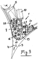
- the invention Device which is generally designated 1, in the free space 2, which is formed between a gripper cylinder 3 and a folding cylinder 4, respectively.
- the gripper cylinder 3 moves in the direction of the arrow (f) while the folding cylinder 4 moves in the direction of the arrow (g).
- a receptacle 6 is arranged, which is shown in Figure 1 only for a device side.
- the holder 6 receives, with the interposition of a pivot pin 7, a plate 8, which is arranged in a second plane behind the holder 6.
- the drive rod 9 of a piston-cylinder unit 10 is operatively connected and the piston-cylinder unit 10 is received by an arm 11 which is part of the fixed structure 5 of the folding machine.
- a display pin 12 from which is movably disposed in a slot 13 which is incorporated in the body of the bearing 6.
- the elongated hole 13 is provided with a graduated scale 40 in order to provide the possibility to accurately display the position of the pin and thus the position of the plate 8.
- the plate 8 and the bearing 6 are penetrated by a screw 14 which is pivotable or adjustable in position about its horizontal axis, a body 15 receives, which takes the form of an oval body extending over the entire length of the cylinder 3 and 4 ,
- the cross-sectionally oval shaped body 15 has a locking screw 16, which is displaceable in the dissolved position in the interior of a slot 17, wherein the slot is incorporated in the plate 8.
- the receptacle 6 receives on the outside a device consisting of a threaded spindle and a gear, and is generally designated 20 and will be described in more detail with reference to Figure 2.
- the device 20 consists of a threaded spindle 21 which is formed at one end 22 such that an actuating key can be placed.
- the drive of the device 20 could also be achieved with the aid of a controllable motor (M), e.g. a distance controllable motor (M) are driven to bring the components 21, 23 in the desired position (see Figure 2).
- a controllable motor e.g. a distance controllable motor (M) are driven to bring the components 21, 23 in the desired position (see Figure 2).
- the threaded spindle acts on a gear 23, which is connected via a pipe or a cylindrical body with the end of a guide belt 24.
- the band 24 partially engages the body 15 of oval cross-section to extend to a tensioning device 25 which is operatively connected to the receptacle 5.
- the working length of the band 24 is dependent on the position of the oval body 15, it will be appreciated that depending on the position of the oval body 15, the length of the band 24 must be adjusted, ie the band 24 is to be shortened or to extend to ensure that the band 24 is always applied to the oval body, thanks to one of the Piston-cylinder unit 9, 10 transmitted compressive force.
- a band 24 is used, which has a surface with very low sliding resistance.
- a tape coated with a layer of Teflon (R) or other friction reducing material e.g. Teflon (R) or other friction reducing material.
- This piston-cylinder unit presses the plate 8 and thus the oval in cross-section formed body 15 permanently against the belt 24, whereby the belt 24 always remains taut and thereby allows accurate guidance for the signatures.
Landscapes
- Folding Of Thin Sheet-Like Materials, Special Discharging Devices, And Others (AREA)
Applications Claiming Priority (1)
| Application Number | Priority Date | Filing Date | Title |
|---|---|---|---|
| IT001482A ITMI20051482A1 (it) | 2005-07-29 | 2005-07-29 | Dispositivo per condurre delle segnature tra due cilindri di una piegatrice |
Publications (2)
| Publication Number | Publication Date |
|---|---|
| EP1748014A2 true EP1748014A2 (fr) | 2007-01-31 |
| EP1748014A3 EP1748014A3 (fr) | 2007-10-03 |
Family
ID=37101531
Family Applications (1)
| Application Number | Title | Priority Date | Filing Date |
|---|---|---|---|
| EP06004203A Withdrawn EP1748014A3 (fr) | 2005-07-29 | 2006-03-02 | Dispositif pour le guidage de feuilles entre deux cylindres d'un appareil de pliage |
Country Status (3)
| Country | Link |
|---|---|
| US (1) | US7377892B2 (fr) |
| EP (1) | EP1748014A3 (fr) |
| IT (1) | ITMI20051482A1 (fr) |
Families Citing this family (1)
| Publication number | Priority date | Publication date | Assignee | Title |
|---|---|---|---|---|
| US9878871B2 (en) * | 2012-12-31 | 2018-01-30 | Goss International Americas, Inc. | Dynamic guide for a paper folding machine |
Family Cites Families (26)
| Publication number | Priority date | Publication date | Assignee | Title |
|---|---|---|---|---|
| US558615A (en) * | 1896-04-21 | saladee | ||
| US1122547A (en) * | 1908-06-12 | 1914-12-29 | Hoe & Co R | Delivery mechanism for printing-machines. |
| US1979093A (en) * | 1933-02-01 | 1934-10-30 | Cottrell C B & Sons Co | Signature handling mechanism for printing presses |
| US2222279A (en) * | 1939-10-26 | 1940-11-19 | Cottrell C B & Sons Co | Associating and folding mechanism |
| US2659437A (en) * | 1947-03-04 | 1953-11-17 | Huck Co | Cutting and gripping mechanism for printing machines |
| US3758102A (en) * | 1971-05-28 | 1973-09-11 | Hantscho Co George | Signature cutting and trimming apparatus |
| US4099710A (en) * | 1976-08-10 | 1978-07-11 | Graphics Equipment International Corporation | Radial roll folder |
| DE2931968B1 (de) * | 1979-08-07 | 1981-07-16 | Heidelberger Druckmaschinen Ag, 6900 Heidelberg | Falzapparat an Rollen-Rotationsdruckmaschinen |
| US4494949A (en) * | 1983-01-10 | 1985-01-22 | The Lehigh Press, Inc. | Sheet folding apparatus and method |
| DE3321577A1 (de) * | 1983-06-15 | 1984-12-20 | Heidelberger Druckmaschinen Ag, 6900 Heidelberg | Bremsbuersten im falzapparat von rotationsdruckmaschinen |
| DE3512308A1 (de) * | 1985-04-04 | 1986-10-16 | Albert-Frankenthal Ag, 6710 Frankenthal | Falzapparat |
| DE3601660A1 (de) * | 1986-01-21 | 1987-07-23 | Eltex Elektrostatik Gmbh | Verfahren und vorrichtung zum falzen von aus einer fortlaufenden materialbahn abgeschnittenen bogen |
| DE3705195A1 (de) * | 1987-02-19 | 1988-09-01 | Frankenthal Ag Albert | Leiteinrichtung |
| US4842574A (en) * | 1987-07-21 | 1989-06-27 | Noble Noel L | Buckle chute folder having sheet squaring feature |
| DE8809285U1 (de) * | 1988-07-20 | 1988-09-01 | Heidelberger Druckmaschinen Ag, 6900 Heidelberg | Vorrichtung zum Leiten von Exemplarabschnitten im Falzapparat von Rotationsdruckmaschinen |
| US5226871A (en) * | 1991-07-03 | 1993-07-13 | Rockwell International Corporation | Folder with gradual guide assembly and method |
| DE4342037C1 (de) * | 1993-12-09 | 1995-03-02 | Frankenthal Ag Albert | Verfahren und Vorrichtung zum Querfalzen von Signaturen |
| US5588945A (en) * | 1995-02-21 | 1996-12-31 | Corrugated Gear & Services, Inc. | Method and device for spacing a corrugating finger relative to a corrugating roll |
| DE19515268C1 (de) * | 1995-04-26 | 1996-08-08 | Roland Man Druckmasch | Falzapparat zum wahlweisen Herstellen von einmal oder zweimal quergefalzten Produkten |
| DE19708213A1 (de) * | 1996-04-09 | 1997-10-30 | Heidelberger Druckmasch Ag | Verfahren und Vorrichtung zur Produktführung in einem Falzbildungsbereich eines Falzapparates |
| US5967963A (en) * | 1996-11-26 | 1999-10-19 | Grapha-Holding Ag | Apparatus for folding paper sheets |
| DE19932070A1 (de) * | 1998-07-27 | 2000-02-03 | Heidelberger Druckmasch Ag | Exemplarführungseinrichtung mit variabler Geometrie |
| AU2001265787A1 (en) * | 2000-05-17 | 2001-11-26 | Koenig And Bauer Aktiengesellschaft | Automotive transversally displaceable folding blade cylinder |
| US6605027B1 (en) * | 2000-11-16 | 2003-08-12 | Heidelberger Druckmaschinen Ag | Fold-off guide for a folder in a paper-processing machine |
| DK174943B1 (da) * | 2002-02-13 | 2004-03-15 | Inter Ikea Sys Bv | Maskine til udstansning af emner fra en bane af bølgepap samt til dannelse af bukkeanvisningslinier i emnerne |
| JP3697694B2 (ja) * | 2002-05-09 | 2005-09-21 | 株式会社東京機械製作所 | 輪転機の折部の咥え装置 |
-
2005
- 2005-07-29 IT IT001482A patent/ITMI20051482A1/it unknown
-
2006
- 2006-02-23 US US11/361,145 patent/US7377892B2/en not_active Expired - Fee Related
- 2006-03-02 EP EP06004203A patent/EP1748014A3/fr not_active Withdrawn
Also Published As
| Publication number | Publication date |
|---|---|
| ITMI20051482A1 (it) | 2007-01-30 |
| US20070027013A1 (en) | 2007-02-01 |
| US7377892B2 (en) | 2008-05-27 |
| EP1748014A3 (fr) | 2007-10-03 |
Similar Documents
| Publication | Publication Date | Title |
|---|---|---|
| DE102014016630B4 (de) | Verstelleinrichtung für eine Druckrolle einer Bearbeitungsmaschine, insbesondere Kehlmaschine, sowie Bearbeitsmaschine, insbesondere Kehlmaschine, mit einer solchen Verstelleinrichtung | |
| DE2627972C2 (de) | Schwenkbiegemaschine | |
| DE3322944A1 (de) | Matrizenauswerfer-vorrichtung fuer mehrstufen-umformmaschinen | |
| EP0462324A1 (fr) | Dispositif de serrage pour le serrage de pièces à usiner | |
| DE3619244A1 (de) | Verfahren und vorrichtung fuer die streichblattbeschichtung einer sich bewegenden materialbahn | |
| EP2011749B1 (fr) | Dispositif de serrage d'un élément en rotation | |
| DE723416C (de) | Vorrichtung zum Einstellen der einzeln fuer sich verstellbaren, auf einer hin und her schwingenden Tragspindel angeordneten Anlegemarken | |
| DE19959457B4 (de) | Vorrichtung zum Vorschub eines Sägebandes | |
| EP0933203A1 (fr) | Pince à dépression pour transférer le bord postérieur d'une feuille dans une machine à imprimer des feuilles rotative | |
| WO2010006572A1 (fr) | Granulateur de joncs à espace de coupe réglable | |
| DE3011626A1 (de) | Vorrichtung zum seitlichen ausrichten von selbsttaetig zugefuehrten bogen an druckmaschinen | |
| DE1811801A1 (de) | Einrichtung zum Zufuehren von Blaettern zu einer Druckmaschine | |
| DE9411121U1 (de) | Greiferzylinder in einem Falzapparat | |
| DE1577652B2 (de) | Beschichtungsvorrichtung fuer eine papierbahn | |
| EP1304181A1 (fr) | Dispositif pour l' avancement pas à pas d' une pièce en forme de bande | |
| EP0352625A2 (fr) | Dispositif de pliage de feuilles pour machine d'impression | |
| DE2723845A1 (de) | Vorrichtung zum positionieren einer farb-zumesseinrichtung an einer farbkastenwalze | |
| DE2711557A1 (de) | Vorrichtung zum schneiden von laenglichen werkstuecken | |
| EP1681253B1 (fr) | Dispositif de guidage | |
| DE10344402B4 (de) | Leitvorrichtung zur Bogenzufuhr an einer Druckmaschine | |
| DE102006013635B3 (de) | Spannvorrichtung für ein Endlosband | |
| DE298231C (fr) | ||
| DE2055888C3 (de) | Vorrichtung an Schälmaschinen zum Zu- bzw. Abführen von Stranggut oder dessen Abschnitte wie Stangen oder Rohre | |
| DE439141C (de) | Abnehmbare Hilfsvorrichtung fuer Druckmaschinen, die wahlweise Hand- oder selbsttaetige Anlegung und Geradlegung der zu bedruckenden Bogen ermoeglicht | |
| DE121669C (fr) |
Legal Events
| Date | Code | Title | Description |
|---|---|---|---|
| PUAI | Public reference made under article 153(3) epc to a published international application that has entered the european phase |
Free format text: ORIGINAL CODE: 0009012 |
|
| AK | Designated contracting states |
Kind code of ref document: A2 Designated state(s): AT BE BG CH CY CZ DE DK EE ES FI FR GB GR HU IE IS IT LI LT LU LV MC NL PL PT RO SE SI SK TR |
|
| AX | Request for extension of the european patent |
Extension state: AL BA HR MK YU |
|
| 17P | Request for examination filed |
Effective date: 20070615 |
|
| PUAL | Search report despatched |
Free format text: ORIGINAL CODE: 0009013 |
|
| AK | Designated contracting states |
Kind code of ref document: A3 Designated state(s): AT BE BG CH CY CZ DE DK EE ES FI FR GB GR HU IE IS IT LI LT LU LV MC NL PL PT RO SE SI SK TR |
|
| AX | Request for extension of the european patent |
Extension state: AL BA HR MK YU |
|
| STAA | Information on the status of an ep patent application or granted ep patent |
Free format text: STATUS: THE APPLICATION HAS BEEN WITHDRAWN |
|
| 18W | Application withdrawn |
Effective date: 20071205 |