EP1748135A2 - Chariot et rail de guidage - Google Patents
Chariot et rail de guidage Download PDFInfo
- Publication number
- EP1748135A2 EP1748135A2 EP06450103A EP06450103A EP1748135A2 EP 1748135 A2 EP1748135 A2 EP 1748135A2 EP 06450103 A EP06450103 A EP 06450103A EP 06450103 A EP06450103 A EP 06450103A EP 1748135 A2 EP1748135 A2 EP 1748135A2
- Authority
- EP
- European Patent Office
- Prior art keywords
- roller
- door
- profile
- door leaf
- set according
- Prior art date
- Legal status (The legal status is an assumption and is not a legal conclusion. Google has not performed a legal analysis and makes no representation as to the accuracy of the status listed.)
- Granted
Links
Images


Classifications
-
- E—FIXED CONSTRUCTIONS
- E05—LOCKS; KEYS; WINDOW OR DOOR FITTINGS; SAFES
- E05D—HINGES OR SUSPENSION DEVICES FOR DOORS, WINDOWS OR WINGS
- E05D15/00—Suspension arrangements for wings
- E05D15/06—Suspension arrangements for wings for wings sliding horizontally more or less in their own plane
- E05D15/0621—Details, e.g. suspension or supporting guides
- E05D15/0626—Details, e.g. suspension or supporting guides for wings suspended at the top
- E05D15/063—Details, e.g. suspension or supporting guides for wings suspended at the top on wheels with fixed axis
-
- E—FIXED CONSTRUCTIONS
- E05—LOCKS; KEYS; WINDOW OR DOOR FITTINGS; SAFES
- E05D—HINGES OR SUSPENSION DEVICES FOR DOORS, WINDOWS OR WINGS
- E05D15/00—Suspension arrangements for wings
- E05D15/06—Suspension arrangements for wings for wings sliding horizontally more or less in their own plane
- E05D15/0621—Details, e.g. suspension or supporting guides
- E05D15/0626—Details, e.g. suspension or supporting guides for wings suspended at the top
- E05D15/0652—Tracks
-
- E—FIXED CONSTRUCTIONS
- E06—DOORS, WINDOWS, SHUTTERS, OR ROLLER BLINDS IN GENERAL; LADDERS
- E06B—FIXED OR MOVABLE CLOSURES FOR OPENINGS IN BUILDINGS, VEHICLES, FENCES OR LIKE ENCLOSURES IN GENERAL, e.g. DOORS, WINDOWS, BLINDS, GATES
- E06B5/00—Doors, windows, or like closures for special purposes; Border constructions therefor
- E06B5/10—Doors, windows, or like closures for special purposes; Border constructions therefor for protection against air-raid or other war-like action; for other protective purposes
- E06B5/16—Fireproof doors or similar closures; Adaptations of fixed constructions therefor
- E06B5/164—Sealing arrangements between the door or window and its frame, e.g. intumescent seals specially adapted therefor
-
- E—FIXED CONSTRUCTIONS
- E05—LOCKS; KEYS; WINDOW OR DOOR FITTINGS; SAFES
- E05Y—INDEXING SCHEME ASSOCIATED WITH SUBCLASSES E05D AND E05F, RELATING TO CONSTRUCTION ELEMENTS, ELECTRIC CONTROL, POWER SUPPLY, POWER SIGNAL OR TRANSMISSION, USER INTERFACES, MOUNTING OR COUPLING, DETAILS, ACCESSORIES, AUXILIARY OPERATIONS NOT OTHERWISE PROVIDED FOR, APPLICATION THEREOF
- E05Y2800/00—Details, accessories and auxiliary operations not otherwise provided for
- E05Y2800/40—Physical or chemical protection
- E05Y2800/414—Physical or chemical protection against high or low temperatures
- E05Y2800/416—Physical or chemical protection against high or low temperatures against fire
-
- E—FIXED CONSTRUCTIONS
- E05—LOCKS; KEYS; WINDOW OR DOOR FITTINGS; SAFES
- E05Y—INDEXING SCHEME ASSOCIATED WITH SUBCLASSES E05D AND E05F, RELATING TO CONSTRUCTION ELEMENTS, ELECTRIC CONTROL, POWER SUPPLY, POWER SIGNAL OR TRANSMISSION, USER INTERFACES, MOUNTING OR COUPLING, DETAILS, ACCESSORIES, AUXILIARY OPERATIONS NOT OTHERWISE PROVIDED FOR, APPLICATION THEREOF
- E05Y2900/00—Application of doors, windows, wings or fittings thereof
- E05Y2900/10—Application of doors, windows, wings or fittings thereof for buildings or parts thereof
- E05Y2900/13—Type of wing
- E05Y2900/132—Doors
- E05Y2900/134—Fire doors
Definitions
- the invention relates to a chassis for a door leaf element of a fire door or a door, comprising at least one support roller which is rotatably mounted about a supporting roller rotation axis, wherein the chassis is arranged at an upper end of a door leaf element.
- chassis should ensure easy mobility of the fire door or door. Most of them carry the entire weight of the door and also take over their precise guidance.
- the chassis is arranged to roll on a running rail.
- trolleys have become known in which the support roller and the running rail each have a profile, that is a cross-sectional shape, with which forces in the direction of the support roller rotation axis of the support roller can be transferred to the running rail, so that the position of the at least one support roller is set on the running rail in the direction of the support roller rotation axis.
- the invention therefore also relates to a chassis for a door leaf element of a fire protection door or a door, consisting of at least two support rollers, which are arranged rotatably about the same axis or about mutually parallel axes, wherein the chassis can be arranged at an upper end of a door leaf element, so at least a first of the support rollers comes to rest on a first side of the longitudinal center plane of the door leaf element and at least a second of the support rollers on a second side of the longitudinal center plane of the door leaf element.
- Such a constructed chassis for a fire sliding door is for example from the German utility model DE 86 05 369.2 U known.
- the individual door leaf elements of the fire doors are each suspended with its own chassis on a running rail.
- the individual wheels of the chassis are all the same structure and have the same profile.
- the lateral guidance is realized via lateral contact surfaces in the running rail.
- a disadvantage of this known design is that the contact surfaces must be located very close to the support rollers. As a result, there is a risk that, if the distance of the contact surfaces is greater than the outer distance of the support rollers, clearance occurs. This in turn does not allow accurate positioning of the door, which can lead to leaks and therefore reduced fire safety. On the other hand, there is a risk that, if the distance of the contact surfaces is smaller than the outer distance of the support rollers, the chassis can jam in the track rail. This poses a great danger, because in this case the door can not be closed securely and thus there is no fire protection at all.
- the chassis should have a high load capacity and ensure good lateral guidance.
- the profile of the at least one support roller and the profile of the track are designed such that, when the at least one support roller is placed on the track, touching two delimited contact areas along the circumference of the at least one support roller ,
- a contact region can counteract a displacement in a first direction parallel to the support roller rotation axis, and the other contact region can counteract a displacement in the opposite direction parallel to the support roller rotation axis. Since at the same time in both areas a contact of carrier roller and track rail is made, thus a deflection in each of the two directions is prevented. The force counteracting a deflection acts immediately, which means even with slight deflections. Unlike idlers, which have only one - albeit large - Have contact area, no initial deflection is necessary in the inventive solution to build such a force first. Therefore, a support roller according to the invention can ensure an exact side guide that makes a side deflection directly resistance. At the same time, easy movability is achieved. In addition, the suspension according to the invention need not be adjusted, since the two contact areas allow self-adjustment.
- the profile of the at least one support roller and the profile of the track can be designed such that they touch at two defined points along a circumferential line of the at least one support roller.
- the at least one support roller has a substantially V-shaped or U-shaped, preferably inwardly curved profile.
- the support roller can be easily placed from above on the track and a door equipped with it can be hung. In this way, moreover, a precise lateral positioning of the door leaf element is possible in a simple manner.
- At least one second support roller is provided, which, however, has a profile which can not transmit forces in the direction of the support roller rotation axis.
- this second support roller can absorb part of the weight of the door, such as a fire door. Since this second support roller itself can transmit no axial forces, the position of the chassis is still determined transversely to the process direction only by the first support roller. So jamming of the chassis can be effectively prevented.
- the at least one second support roller has a substantially planar or convex profile.
- the associated track can be particularly simple, especially designed flat. Also, this increases the carrying capacity of the second support roller. Moreover, this ensures that no lateral forces are transmitted to the second support roller and therefore it can not lead to jamming of the door or the door.
- At least one further running rail can be provided, on which the at least one second carrying roller can roll.
- each rail can be configured specifically to the particular type of support roller and thus be matched to the particular task of guiding and / or wearing.
- the support rollers are arranged opposite one another on the same axis of rotation or on mutually parallel axes of rotation, so that in use at least one of the support rollers on a first side of the longitudinal center plane of the door leaf element and at least one other of the support rollers on a second side of the longitudinal center plane the door leaf element comes to rest.
- a particularly simple, but in particular symmetrical structure can be achieved.
- the rails are integrally formed from a rail profile.
- a particularly easy to manufacture design is possible, which also provides an improved tightness.
- a fire door or door can be composed of any width.
- a recess may be provided on the underside of the door leaf element, which, when using the door leaf element in a door or a door, can accommodate a bottom-mounted guide roller.
- the leadership of the door or the door is also guaranteed at the bottom.
- the door or the door can also be guided on the underside and thus also withstands loads resulting from pressure differences between the two sides of the door or the door. As a result, both leadership and tightness can be further improved.
- At least one lateral guide surface can be provided in the recess.
- the leadership can attack and thus ensure a well-defined side guide in the lower region of the door or the door.
- the lateral guide can have less frictional resistance and ensure particularly precise guidance.
- door leaf elements can also be provided two or more door leaf elements. These can together form a fire protection door or a door. In this case, for example, by tongue and groove connections a simple assembly of the individual door leaf elements possible to a gate or a door. It can be formed with several standard door leaf elements gates and doors of any width.
- At least one roller can be provided in the set, which can be installed substantially in the vertical direction with its axis of rotation, so that in use the roller can penetrate into the recess.
- the roller can be optimally adapted for their function for lateral guidance on the recess on the underside of the door leaf element or the elements. This can be turned off already in the production of a good interaction of leadership and recess and thus a good and accurate leadership.
- the roller has a profile which cooperates in use with the or the lateral guide surfaces. Due to the special selection of a profile for the roller can be ensured that on the one hand a good lateral guidance is guaranteed in the lower region of the door or the door, on the other hand, however, no increased friction, but no jamming occurs.
- the profile can be curved, for example, to the outside. Alternatively, it may just be formed with rounded edges. This ensures that such a constructed door or door is easily movable and at the same time accurately positioned.
- a chassis for a door leaf element of a fire door or door which consists of at least two support rollers which are arranged rotatably about the same axis or about mutually parallel axes.
- the first support roller having a profile which can transmit axial forces, so that the position of the first support roller is fixed in the direction of the axis
- the second support roller has a profile which can not transmit axial forces, so that a displacement of the second support roller in Direction of the axis is possible.
- a door equipped with such a landing gear or a door can hang freely on the carrying rollers without any lateral forces.
- a set comprising an inventive chassis and at least two rails, on which the support rollers are arranged rollable to form.
- a first track rail having a cooperating with the first support roller cross-sectional shape, so that the position of the first support roller is fixed in the direction of the axis of the first support roller. This ensures that the first support roller can actually absorb the axial forces.
- a second running rail can then have a cross-sectional shape cooperating with the second carrying roller, so that the position of the second carrying roller in the direction of the axis of the second carrying roller is determined only indirectly by the interaction of the first carrying roller and the first running rail. This ensures that the second support roller transmits no axial forces and therefore can not lead to a jamming of the door or the door.
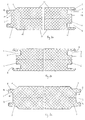
- the fire protection door shown consists of several individual door leaf elements 40, 50, 60, etc., which lined up form a gate or door leaf.
- the terms "gate” and "door” are not to be further distinguished. Rather, it should be clear that the statements made for a goal apply equally to a door, and vice versa.
- Each door leaf element has a core 15 of heat-insulating material, which is enveloped by a metal jacket.
- the metal jacket is formed from a first sheet metal shell 31 and a second sheet metal shell 32.
- the two sheet metal shells 31 and 32 surround the core 15 only in partial areas, in a partial area near the longitudinal center plane L, the core 15 is not covered by any sheet metal shell.
- this part is located after the joining of several door leaf elements inside the gate, so that on the outside still creates a closed metal jacket.
- the sheath-free zone effectively prevents the formation of a thermal bridge from one side of the gate to the other.
- a first spring 3 is formed on the door leaf element on one side and a first groove 4 on a second side.
- a first end face 1 of a door leaf element shown a first spring 3 is arranged.
- a further groove 7 is formed.
- a further spring 6 is arranged.
- the springs and grooves are matched to one another such that the profile of a first end face 1 can be inserted into the profile of a second end face 2 of a similarly constructed door leaf element.
- the profiles of grooves and springs complement each other in such a way that over the cross-section of the gate results in a shock with a zigzag course. This zigzag course ensures an improved sealing effect of the labyrinth seal formed thereby.
- a first groove 4 is formed on the door leaf element on both sides. This can be joined together with a counterpart, that is to say with a first spring 3 formed on both end faces. Such a counterpart door leaf element is shown in Figure 2c.
- the exact course of the frontal, formed from a sheet metal shell 31 profiles is shown in Figures 3 and 4.
- the outer side surface 8 of the first spring 3 with respect to the longitudinal center plane L at a first angle ⁇ is obliquely executed on the first end face 1 shown on the left.
- the inner side surface 9 of the first groove 4 is inclined relative to the longitudinal center plane L at precisely this first angle ⁇ .
- the first angle ⁇ drawn in the exemplary embodiment is approximately 2 °, but it may also have other suitable values. However, it should be ensured that the individual door leaf elements are held together by the wedge effect.
- the inner side surface 11 of the further groove 7, which is arranged on the end face 12 of the first spring 3, could be designed obliquely with respect to the longitudinal center plane.
- the outer side surface 10 of the further spring 6, which is arranged on the base surface 5 of the first groove 4 would be executed obliquely with respect to the longitudinal center plane L.
- the first end face 1 and the second end face 2 extend at a second angle ⁇ obliquely with respect to the longitudinal center plane L of the door leaf element. This results in an assembly of the individual door leaf elements at each impact a V-shaped recess.
- FIG. 5a shows a frontal closure of a fire protection door with a profile 16 projecting on one side.
- a closure profile with a molded body 20 is inserted on the side of the first spring 3 in the further groove 7, a closure profile with a molded body 20 is inserted.
- the molded body 20 has a shape corresponding to the inner contour of the further groove 7, so that it is securely held in the further groove 7.
- the unilaterally projecting profile 16 is angled at its projecting free end 17 in the closing direction of the door. Therefore, when closing the door, it is possible for a frame-mounted, oppositely shaped profile 19 to engage behind its free end 18 and thus produce a labyrinth-like seal. At its non-protruding other end, the profile 16 on a conclusion 21.
- This conclusion 21 completes the outer contour of the outermost door leaf element to a full rectangle, so that there is a flush surface. As a result, even the outermost door leaf element can be constructed the same as all other door leaf elements and it still results in a clean conclusion, without that on the front side 12 of the outermost door leaf element an outwardly open groove or a protruding spring would be visible.
- FIG. 5b shows a frontal closure of a fire protection door with a shaped body 33.
- the molded body 33 may be surrounded with a metal jacket in the form of a front C-profile 35 and may be inserted into the first groove 4.
- the molded body 33 thus forms a conclusion and completes the outer contour of the outermost door leaf element to a full cross section, so that there is a flush or closed surface.
- the outermost door leaf element on the inlet side of the door leaf can be constructed the same as the other door leaf elements and it still results in a clean conclusion, without that on the front side of the outermost door leaf element an outwardly open groove or a protruding spring would be visible.
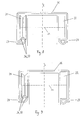
- a landing gear is arranged on the upper side of a door or a door leaf element.
- the gate or the door leaf element along rails 27 and 28 are moved.
- the running gear comprises at least one carrying roller 21. In the example shown, this is arranged on a first side of the longitudinal center plane L of the door leaf element.
- a second support roller 22 is provided on a second side of the longitudinal center plane L of the door leaf element.
- the first support roller 21 has a profile which can transmit axial forces. In the illustrated embodiment, this is a V-shaped inwardly curved profile. Alternatively, however, any other shape would be possible that can transmit axial forces, such as a U-shaped profile or an outwardly curved profile, which then with a recess in an inwardly curved running rail could work together. In the example shown, the axial position of the first support roller and thus of the chassis and the door leaf element is determined together with the outwardly curved first rail 27.
- the profile of the first support roller 21 touches the profile of the first slide rail 27 in two opposite, separate contact areas 37.
- the contact area 37 shown on the right in FIG. 6 acts as deflected to the left - with reference to FIG.
- the opposite, shown in Figure 6 right contact area 37 prevents a deflection after - again refer to the figure 6 - right.
- both areas are approximately punctiform and therefore correspond to points of contact 36.
- the points of contact move along the track 27 on a straight line (not shown in the figures) and along the circumference of the carrying roller 21 a circumferential line 38.
- wider contact areas 37 may be provided. The combination of a wider contact area 37 with a relatively small touch point 36 would be conceivable.
- the arranged on the opposite side of the longitudinal center plane L support roller 22 has a profile which can not transmit axial forces.
- it is a flat profile.
- an outwardly curved profile conceivable.
- the profile cooperates with the second running rail 28 in such a way that no axial forces can be transmitted.
- the axial definition of the second support roller 22 and thus of the chassis and the door leaf element is done exclusively on the first support roller 21 and the first track rail 27. In this way, it is possible to determine the exact axial position of the chassis while ensuring a good mobility. Jamming or tilting is effectively avoided.
- a recess 24 is provided in the door leaf element, in which a guide roller 29 arranged on the bottom side engages.
- the guide roller 29 contacts the door leaf element on one or two opposite guide surfaces 25.
- FIGS. 8 and 9 show further possible embodiments of the cross section of the track profile 26, in particular the track rail 28.
- the heat-insulating material 15 runs essentially over the entire height of the fire protection door, i. also up to over the chassis.
- the heat-insulating material 15 ends shortly below the axle 23 of the running gear. The latter is therefore placed in this embodiment, the heat-insulating material 15.
Landscapes
- Engineering & Computer Science (AREA)
- Mechanical Engineering (AREA)
- Civil Engineering (AREA)
- Structural Engineering (AREA)
- Special Wing (AREA)
Priority Applications (2)
| Application Number | Priority Date | Filing Date | Title |
|---|---|---|---|
| SI200631448T SI1748135T1 (sl) | 2005-07-25 | 2006-07-21 | Protipožarna vrata s podvozjem in tračnicami |
| PL06450103T PL1748135T3 (pl) | 2005-07-25 | 2006-07-21 | Brama przeciwpożarowa z wózkiem i prowadnicą |
Applications Claiming Priority (1)
| Application Number | Priority Date | Filing Date | Title |
|---|---|---|---|
| AT12422005 | 2005-07-25 |
Publications (3)
| Publication Number | Publication Date |
|---|---|
| EP1748135A2 true EP1748135A2 (fr) | 2007-01-31 |
| EP1748135A3 EP1748135A3 (fr) | 2009-05-20 |
| EP1748135B1 EP1748135B1 (fr) | 2012-10-03 |
Family
ID=37076215
Family Applications (1)
| Application Number | Title | Priority Date | Filing Date |
|---|---|---|---|
| EP06450103A Active EP1748135B1 (fr) | 2005-07-25 | 2006-07-21 | Porte coupe-feu avec chariot et rails de guidage |
Country Status (3)
| Country | Link |
|---|---|
| EP (1) | EP1748135B1 (fr) |
| PL (1) | PL1748135T3 (fr) |
| SI (1) | SI1748135T1 (fr) |
Cited By (8)
| Publication number | Priority date | Publication date | Assignee | Title |
|---|---|---|---|---|
| DE102010005188A1 (de) | 2010-01-20 | 2011-07-21 | Tortec Brandschutztor Gmbh | Torblatt für ein Feuerschutzschiebetor mit Schlupftür sowie Herstellverfahren |
| DE202010017436U1 (de) | 2010-06-09 | 2011-10-28 | Hörmann KG Antriebstechnik | Brandschutztor |
| WO2011154214A1 (fr) | 2010-06-09 | 2011-12-15 | Hörmann KG Antriebstechnik | Porte coupe-feu |
| EP2977535A1 (fr) | 2014-07-23 | 2016-01-27 | Tortec Brandschutztor Gesellschaft mbH | Mécanisme de fermeture et dispositif d'entraînement pour une porte pare-feu et porte pare-feu ainsi équipée |
| EP3211162A1 (fr) * | 2016-02-23 | 2017-08-30 | Gebr. Willach GmbH | Système de porte coulissante |
| CN108222740A (zh) * | 2017-10-27 | 2018-06-29 | 中山市欧派克五金制品有限公司 | 一种滑动门用直线电机 |
| CN108252603A (zh) * | 2018-01-31 | 2018-07-06 | 中山市欧派克五金制品有限公司 | 一种导滑轮 |
| EP3508674A4 (fr) * | 2016-08-30 | 2019-09-18 | Zhongshan Opike Hardware Product Co., Ltd | Galet de roulement guidé anti-coincement |
Citations (1)
| Publication number | Priority date | Publication date | Assignee | Title |
|---|---|---|---|---|
| US4467562A (en) | 1982-09-15 | 1984-08-28 | American Metal Door Company, Inc. | Fire door assembly |
Family Cites Families (4)
| Publication number | Priority date | Publication date | Assignee | Title |
|---|---|---|---|---|
| GB1084812A (en) * | 1963-06-06 | 1967-09-27 | Deans And Lightalloys Ltd | Suspension for sliding door |
| GB985868A (en) * | 1969-01-14 | 1965-03-10 | Beckett Laycock & Watkinson | Improvements in and relating to railways and runners therefor |
| AT397276B (de) * | 1986-07-19 | 1994-03-25 | Liberda Viktor | Schiebetor, insbesondere brandschutztor |
| DE19620045C1 (de) * | 1996-05-18 | 1997-10-16 | Goldbeck Gmbh | Raumtrennwand aus beweglichen Wandelementen |
-
2006
- 2006-07-21 EP EP06450103A patent/EP1748135B1/fr active Active
- 2006-07-21 SI SI200631448T patent/SI1748135T1/sl unknown
- 2006-07-21 PL PL06450103T patent/PL1748135T3/pl unknown
Patent Citations (1)
| Publication number | Priority date | Publication date | Assignee | Title |
|---|---|---|---|---|
| US4467562A (en) | 1982-09-15 | 1984-08-28 | American Metal Door Company, Inc. | Fire door assembly |
Cited By (11)
| Publication number | Priority date | Publication date | Assignee | Title |
|---|---|---|---|---|
| DE102010005188A1 (de) | 2010-01-20 | 2011-07-21 | Tortec Brandschutztor Gmbh | Torblatt für ein Feuerschutzschiebetor mit Schlupftür sowie Herstellverfahren |
| EP2348185A2 (fr) | 2010-01-20 | 2011-07-27 | Tortec Brandschutztor GmbH | Vantail pour une porte coulissante coupe-feu dotée d'une poterne et son procédé de fabrication |
| DE202010017436U1 (de) | 2010-06-09 | 2011-10-28 | Hörmann KG Antriebstechnik | Brandschutztor |
| WO2011154214A1 (fr) | 2010-06-09 | 2011-12-15 | Hörmann KG Antriebstechnik | Porte coupe-feu |
| EP2977535A1 (fr) | 2014-07-23 | 2016-01-27 | Tortec Brandschutztor Gesellschaft mbH | Mécanisme de fermeture et dispositif d'entraînement pour une porte pare-feu et porte pare-feu ainsi équipée |
| DE102014111927A1 (de) | 2014-07-23 | 2016-01-28 | Tortec Brandschutztor Gmbh | Schließmechanismus und Antriebsvorrichtung für ein Feuerschutztor sowie damit versehenes Feuerschutztor |
| DE102014111927B4 (de) | 2014-07-23 | 2018-05-24 | Tortec Brandschutztor Gmbh | Schließmechanismus und Antriebsvorrichtung für ein Feuerschutztor sowie damit versehenes Feuerschutztor |
| EP3211162A1 (fr) * | 2016-02-23 | 2017-08-30 | Gebr. Willach GmbH | Système de porte coulissante |
| EP3508674A4 (fr) * | 2016-08-30 | 2019-09-18 | Zhongshan Opike Hardware Product Co., Ltd | Galet de roulement guidé anti-coincement |
| CN108222740A (zh) * | 2017-10-27 | 2018-06-29 | 中山市欧派克五金制品有限公司 | 一种滑动门用直线电机 |
| CN108252603A (zh) * | 2018-01-31 | 2018-07-06 | 中山市欧派克五金制品有限公司 | 一种导滑轮 |
Also Published As
| Publication number | Publication date |
|---|---|
| EP1748135A3 (fr) | 2009-05-20 |
| SI1748135T1 (sl) | 2012-11-30 |
| EP1748135B1 (fr) | 2012-10-03 |
| PL1748135T3 (pl) | 2013-02-28 |
Similar Documents
| Publication | Publication Date | Title |
|---|---|---|
| EP0370376B2 (fr) | Vantail de porte | |
| EP0531330A1 (fr) | Element obturateur d'ouvertures carrossables. | |
| EP3380692B1 (fr) | Dispositif de paroi coulissante avec élément de recouvrement | |
| EP2317054B1 (fr) | Porte coulissante | |
| WO2016131909A1 (fr) | Dispositif d'étanchéité pour éléments de fenêtre et éléments de porte | |
| EP0370324B1 (fr) | Vantail de porte | |
| EP1748135B1 (fr) | Porte coupe-feu avec chariot et rails de guidage | |
| EP1354545B1 (fr) | Joint pour une cloison de séparation de douche | |
| EP0300022A1 (fr) | Guidage telescopique. | |
| EP1748140B1 (fr) | Porte ou portail coupe-feu | |
| DE69520540T2 (de) | Einrichtung zur Bewegungssynchronisation der Flügel einer teleskopischen Aufzugstür | |
| DE3423322C2 (fr) | ||
| DE3922995C2 (fr) | ||
| DE3928237C1 (fr) | ||
| AT10012U1 (de) | Fahrwerk und laufschiene | |
| EP1531229A1 (fr) | Connecteur enfilable pour profils creux | |
| DE19719671B4 (de) | Lamelle für ein Torblatt eines zwischen einer Offenstellung und einer Schließstellung bewegbaren Wandverschlusses | |
| DE19618912A1 (de) | Lamelle für ein Blatt eines vorzugsweise auf und ab bewegbaren Rollverschlusses für ein Tor, eine Tür, ein Fenster o. dgl. Öffnung | |
| DE19838205A1 (de) | Sektionaltor | |
| DE2708453C3 (de) | Kastenaufbau für Fahrzeuge mit mindestens einer verschiebbaren Tür | |
| DE19718237C1 (de) | Als Schiebetür oder -tor ausgebildeter Feuerschutzabschluß | |
| DE102018125935A1 (de) | Brandschutzschiebetor | |
| DE3935521C2 (fr) | ||
| DE102018125925A1 (de) | Brandschutzschiebetor | |
| DE8029666U1 (de) | Schleppkettenantrieb |
Legal Events
| Date | Code | Title | Description |
|---|---|---|---|
| PUAI | Public reference made under article 153(3) epc to a published international application that has entered the european phase |
Free format text: ORIGINAL CODE: 0009012 |
|
| AK | Designated contracting states |
Kind code of ref document: A2 Designated state(s): AT BE BG CH CY CZ DE DK EE ES FI FR GB GR HU IE IS IT LI LT LU LV MC NL PL PT RO SE SI SK TR |
|
| AX | Request for extension of the european patent |
Extension state: AL BA HR MK YU |
|
| PUAL | Search report despatched |
Free format text: ORIGINAL CODE: 0009013 |
|
| AK | Designated contracting states |
Kind code of ref document: A3 Designated state(s): AT BE BG CH CY CZ DE DK EE ES FI FR GB GR HU IE IS IT LI LT LU LV MC NL PL PT RO SE SI SK TR |
|
| AX | Request for extension of the european patent |
Extension state: AL BA HR MK RS |
|
| 17P | Request for examination filed |
Effective date: 20091117 |
|
| AKX | Designation fees paid |
Designated state(s): AT BE BG CH CY CZ DE DK EE ES FI FR GB GR HU IE IS IT LI LT LU LV MC NL PL PT RO SE SI SK TR |
|
| 17Q | First examination report despatched |
Effective date: 20100115 |
|
| 17Q | First examination report despatched |
Effective date: 20100326 |
|
| GRAP | Despatch of communication of intention to grant a patent |
Free format text: ORIGINAL CODE: EPIDOSNIGR1 |
|
| RTI1 | Title (correction) |
Free format text: FIREPROOF DOOR WITH CARRIAGE AND GUIDE RAILS |
|
| GRAS | Grant fee paid |
Free format text: ORIGINAL CODE: EPIDOSNIGR3 |
|
| GRAA | (expected) grant |
Free format text: ORIGINAL CODE: 0009210 |
|
| AK | Designated contracting states |
Kind code of ref document: B1 Designated state(s): AT BE BG CH CY CZ DE DK EE ES FI FR GB GR HU IE IS IT LI LT LU LV MC NL PL PT RO SE SI SK TR |
|
| REG | Reference to a national code |
Ref country code: GB Ref legal event code: FG4D Free format text: NOT ENGLISH |
|
| REG | Reference to a national code |
Ref country code: CH Ref legal event code: EP Ref country code: AT Ref legal event code: REF Ref document number: 578073 Country of ref document: AT Kind code of ref document: T Effective date: 20121015 |
|
| REG | Reference to a national code |
Ref country code: IE Ref legal event code: FG4D Free format text: LANGUAGE OF EP DOCUMENT: GERMAN |
|
| REG | Reference to a national code |
Ref country code: CH Ref legal event code: NV Representative=s name: BRAUNPAT BRAUN EDER AG |
|
| REG | Reference to a national code |
Ref country code: DE Ref legal event code: R096 Ref document number: 502006012034 Country of ref document: DE Effective date: 20121129 |
|
| REG | Reference to a national code |
Ref country code: PL Ref legal event code: T3 |
|
| REG | Reference to a national code |
Ref country code: NL Ref legal event code: VDEP Effective date: 20121003 |
|
| REG | Reference to a national code |
Ref country code: LT Ref legal event code: MG4D |
|
| PG25 | Lapsed in a contracting state [announced via postgrant information from national office to epo] |
Ref country code: ES Free format text: LAPSE BECAUSE OF FAILURE TO SUBMIT A TRANSLATION OF THE DESCRIPTION OR TO PAY THE FEE WITHIN THE PRESCRIBED TIME-LIMIT Effective date: 20130114 Ref country code: IS Free format text: LAPSE BECAUSE OF FAILURE TO SUBMIT A TRANSLATION OF THE DESCRIPTION OR TO PAY THE FEE WITHIN THE PRESCRIBED TIME-LIMIT Effective date: 20130203 Ref country code: FI Free format text: LAPSE BECAUSE OF FAILURE TO SUBMIT A TRANSLATION OF THE DESCRIPTION OR TO PAY THE FEE WITHIN THE PRESCRIBED TIME-LIMIT Effective date: 20121003 Ref country code: NL Free format text: LAPSE BECAUSE OF FAILURE TO SUBMIT A TRANSLATION OF THE DESCRIPTION OR TO PAY THE FEE WITHIN THE PRESCRIBED TIME-LIMIT Effective date: 20121003 Ref country code: LT Free format text: LAPSE BECAUSE OF FAILURE TO SUBMIT A TRANSLATION OF THE DESCRIPTION OR TO PAY THE FEE WITHIN THE PRESCRIBED TIME-LIMIT Effective date: 20121003 Ref country code: SE Free format text: LAPSE BECAUSE OF FAILURE TO SUBMIT A TRANSLATION OF THE DESCRIPTION OR TO PAY THE FEE WITHIN THE PRESCRIBED TIME-LIMIT Effective date: 20121003 |
|
| PG25 | Lapsed in a contracting state [announced via postgrant information from national office to epo] |
Ref country code: PT Free format text: LAPSE BECAUSE OF FAILURE TO SUBMIT A TRANSLATION OF THE DESCRIPTION OR TO PAY THE FEE WITHIN THE PRESCRIBED TIME-LIMIT Effective date: 20130204 Ref country code: LV Free format text: LAPSE BECAUSE OF FAILURE TO SUBMIT A TRANSLATION OF THE DESCRIPTION OR TO PAY THE FEE WITHIN THE PRESCRIBED TIME-LIMIT Effective date: 20121003 Ref country code: GR Free format text: LAPSE BECAUSE OF FAILURE TO SUBMIT A TRANSLATION OF THE DESCRIPTION OR TO PAY THE FEE WITHIN THE PRESCRIBED TIME-LIMIT Effective date: 20130104 Ref country code: CY Free format text: LAPSE BECAUSE OF FAILURE TO SUBMIT A TRANSLATION OF THE DESCRIPTION OR TO PAY THE FEE WITHIN THE PRESCRIBED TIME-LIMIT Effective date: 20121003 |
|
| PG25 | Lapsed in a contracting state [announced via postgrant information from national office to epo] |
Ref country code: DK Free format text: LAPSE BECAUSE OF FAILURE TO SUBMIT A TRANSLATION OF THE DESCRIPTION OR TO PAY THE FEE WITHIN THE PRESCRIBED TIME-LIMIT Effective date: 20121003 Ref country code: EE Free format text: LAPSE BECAUSE OF FAILURE TO SUBMIT A TRANSLATION OF THE DESCRIPTION OR TO PAY THE FEE WITHIN THE PRESCRIBED TIME-LIMIT Effective date: 20121003 Ref country code: BG Free format text: LAPSE BECAUSE OF FAILURE TO SUBMIT A TRANSLATION OF THE DESCRIPTION OR TO PAY THE FEE WITHIN THE PRESCRIBED TIME-LIMIT Effective date: 20130103 Ref country code: SK Free format text: LAPSE BECAUSE OF FAILURE TO SUBMIT A TRANSLATION OF THE DESCRIPTION OR TO PAY THE FEE WITHIN THE PRESCRIBED TIME-LIMIT Effective date: 20121003 Ref country code: CZ Free format text: LAPSE BECAUSE OF FAILURE TO SUBMIT A TRANSLATION OF THE DESCRIPTION OR TO PAY THE FEE WITHIN THE PRESCRIBED TIME-LIMIT Effective date: 20121003 |
|
| PLBE | No opposition filed within time limit |
Free format text: ORIGINAL CODE: 0009261 |
|
| STAA | Information on the status of an ep patent application or granted ep patent |
Free format text: STATUS: NO OPPOSITION FILED WITHIN TIME LIMIT |
|
| PG25 | Lapsed in a contracting state [announced via postgrant information from national office to epo] |
Ref country code: RO Free format text: LAPSE BECAUSE OF FAILURE TO SUBMIT A TRANSLATION OF THE DESCRIPTION OR TO PAY THE FEE WITHIN THE PRESCRIBED TIME-LIMIT Effective date: 20121003 Ref country code: IT Free format text: LAPSE BECAUSE OF FAILURE TO SUBMIT A TRANSLATION OF THE DESCRIPTION OR TO PAY THE FEE WITHIN THE PRESCRIBED TIME-LIMIT Effective date: 20121003 |
|
| 26N | No opposition filed |
Effective date: 20130704 |
|
| REG | Reference to a national code |
Ref country code: DE Ref legal event code: R097 Ref document number: 502006012034 Country of ref document: DE Effective date: 20130704 |
|
| BERE | Be: lapsed |
Owner name: TORTEC BRANDSCHUTZTOR GMBH Effective date: 20130731 |
|
| PG25 | Lapsed in a contracting state [announced via postgrant information from national office to epo] |
Ref country code: MC Free format text: LAPSE BECAUSE OF FAILURE TO SUBMIT A TRANSLATION OF THE DESCRIPTION OR TO PAY THE FEE WITHIN THE PRESCRIBED TIME-LIMIT Effective date: 20121003 |
|
| GBPC | Gb: european patent ceased through non-payment of renewal fee |
Effective date: 20130721 |
|
| REG | Reference to a national code |
Ref country code: IE Ref legal event code: MM4A |
|
| REG | Reference to a national code |
Ref country code: FR Ref legal event code: ST Effective date: 20140331 |
|
| PG25 | Lapsed in a contracting state [announced via postgrant information from national office to epo] |
Ref country code: BE Free format text: LAPSE BECAUSE OF NON-PAYMENT OF DUE FEES Effective date: 20130731 Ref country code: GB Free format text: LAPSE BECAUSE OF NON-PAYMENT OF DUE FEES Effective date: 20130721 |
|
| PG25 | Lapsed in a contracting state [announced via postgrant information from national office to epo] |
Ref country code: FR Free format text: LAPSE BECAUSE OF NON-PAYMENT OF DUE FEES Effective date: 20130731 |
|
| REG | Reference to a national code |
Ref country code: SI Ref legal event code: KO00 Effective date: 20140505 |
|
| PG25 | Lapsed in a contracting state [announced via postgrant information from national office to epo] |
Ref country code: IE Free format text: LAPSE BECAUSE OF NON-PAYMENT OF DUE FEES Effective date: 20130721 |
|
| PG25 | Lapsed in a contracting state [announced via postgrant information from national office to epo] |
Ref country code: SI Free format text: LAPSE BECAUSE OF NON-PAYMENT OF DUE FEES Effective date: 20130722 |
|
| PG25 | Lapsed in a contracting state [announced via postgrant information from national office to epo] |
Ref country code: TR Free format text: LAPSE BECAUSE OF FAILURE TO SUBMIT A TRANSLATION OF THE DESCRIPTION OR TO PAY THE FEE WITHIN THE PRESCRIBED TIME-LIMIT Effective date: 20121003 |
|
| PG25 | Lapsed in a contracting state [announced via postgrant information from national office to epo] |
Ref country code: HU Free format text: LAPSE BECAUSE OF FAILURE TO SUBMIT A TRANSLATION OF THE DESCRIPTION OR TO PAY THE FEE WITHIN THE PRESCRIBED TIME-LIMIT; INVALID AB INITIO Effective date: 20060721 Ref country code: LU Free format text: LAPSE BECAUSE OF NON-PAYMENT OF DUE FEES Effective date: 20130721 |
|
| REG | Reference to a national code |
Ref country code: DE Ref legal event code: R082 Ref document number: 502006012034 Country of ref document: DE Representative=s name: KASTEL PATENTANWAELTE, DE Ref country code: DE Ref legal event code: R082 Ref document number: 502006012034 Country of ref document: DE Representative=s name: KASTEL PATENTANWAELTE PARTG MBB, DE |
|
| REG | Reference to a national code |
Ref country code: CH Ref legal event code: PCAR Free format text: NEW ADDRESS: HOLEESTRASSE 87, 4054 BASEL (CH) |
|
| P01 | Opt-out of the competence of the unified patent court (upc) registered |
Effective date: 20230523 |
|
| PGFP | Annual fee paid to national office [announced via postgrant information from national office to epo] |
Ref country code: DE Payment date: 20250919 Year of fee payment: 20 |
|
| PGFP | Annual fee paid to national office [announced via postgrant information from national office to epo] |
Ref country code: AT Payment date: 20250721 Year of fee payment: 20 |
|
| PGFP | Annual fee paid to national office [announced via postgrant information from national office to epo] |
Ref country code: CH Payment date: 20250801 Year of fee payment: 20 |
|
| PGFP | Annual fee paid to national office [announced via postgrant information from national office to epo] |
Ref country code: PL Payment date: 20250709 Year of fee payment: 20 |