EP1748170A2 - Zapfwellenantrieb einer Gasturbine, Gasturbine und verfahren zum Betreiben einer Gasturbine - Google Patents
Zapfwellenantrieb einer Gasturbine, Gasturbine und verfahren zum Betreiben einer Gasturbine Download PDFInfo
- Publication number
- EP1748170A2 EP1748170A2 EP06253912A EP06253912A EP1748170A2 EP 1748170 A2 EP1748170 A2 EP 1748170A2 EP 06253912 A EP06253912 A EP 06253912A EP 06253912 A EP06253912 A EP 06253912A EP 1748170 A2 EP1748170 A2 EP 1748170A2
- Authority
- EP
- European Patent Office
- Prior art keywords
- shaft
- power take
- drive
- gas turbine
- turbine engine
- Prior art date
- Legal status (The legal status is an assumption and is not a legal conclusion. Google has not performed a legal analysis and makes no representation as to the accuracy of the status listed.)
- Withdrawn
Links
Images

Classifications
-
- F—MECHANICAL ENGINEERING; LIGHTING; HEATING; WEAPONS; BLASTING
- F02—COMBUSTION ENGINES; HOT-GAS OR COMBUSTION-PRODUCT ENGINE PLANTS
- F02K—JET-PROPULSION PLANTS
- F02K3/00—Plants including a gas turbine driving a compressor or a ducted fan
- F02K3/02—Plants including a gas turbine driving a compressor or a ducted fan in which part of the working fluid by-passes the turbine and combustion chamber
- F02K3/04—Plants including a gas turbine driving a compressor or a ducted fan in which part of the working fluid by-passes the turbine and combustion chamber the plant including ducted fans, i.e. fans with high volume, low pressure outputs, for augmenting the jet thrust, e.g. of double-flow type
-
- F—MECHANICAL ENGINEERING; LIGHTING; HEATING; WEAPONS; BLASTING
- F02—COMBUSTION ENGINES; HOT-GAS OR COMBUSTION-PRODUCT ENGINE PLANTS
- F02C—GAS-TURBINE PLANTS; AIR INTAKES FOR JET-PROPULSION PLANTS; CONTROLLING FUEL SUPPLY IN AIR-BREATHING JET-PROPULSION PLANTS
- F02C7/00—Features, components parts, details or accessories, not provided for in, or of interest apart form groups F02C1/00 - F02C6/00; Air intakes for jet-propulsion plants
- F02C7/36—Power transmission arrangements between the different shafts of the gas turbine plant, or between the gas-turbine plant and the power user
-
- F—MECHANICAL ENGINEERING; LIGHTING; HEATING; WEAPONS; BLASTING
- F05—INDEXING SCHEMES RELATING TO ENGINES OR PUMPS IN VARIOUS SUBCLASSES OF CLASSES F01-F04
- F05D—INDEXING SCHEME FOR ASPECTS RELATING TO NON-POSITIVE-DISPLACEMENT MACHINES OR ENGINES, GAS-TURBINES OR JET-PROPULSION PLANTS
- F05D2260/00—Function
- F05D2260/40—Transmission of power
- F05D2260/403—Transmission of power through the shape of the drive components
- F05D2260/4031—Transmission of power through the shape of the drive components as in toothed gearing
-
- F—MECHANICAL ENGINEERING; LIGHTING; HEATING; WEAPONS; BLASTING
- F05—INDEXING SCHEMES RELATING TO ENGINES OR PUMPS IN VARIOUS SUBCLASSES OF CLASSES F01-F04
- F05D—INDEXING SCHEME FOR ASPECTS RELATING TO NON-POSITIVE-DISPLACEMENT MACHINES OR ENGINES, GAS-TURBINES OR JET-PROPULSION PLANTS
- F05D2260/00—Function
- F05D2260/85—Starting
Definitions
- the present invention relates generally to gas turbines, and more particularly to a power take off drive assembly for a gas turbine.
- a gas turbine engine includes a compressor that provides pressurized air to a combustor wherein the air is mixed with fuel and ignited for generating hot combustion gases. These gases flow downstream to one or more turbines that extract energy therefrom to power the compressor and provide useful work such as powering an aircraft in flight.
- a turbofan engine which typically includes a fan placed at the front of the core engine, a high pressure turbine powers the compressor of the core engine. A low pressure turbine is disposed downstream from the high pressure turbine for powering the fan.
- a gas turbine engine In addition to providing thrust for flight, a gas turbine engine must operate additional power-absorbing accessories such as electrical generators, fuel pumps, hydraulic pumps, and the like. Accordingly, a power take off or "PTO" drive is required. Typically this is implemented by connecting a PTO shaft to the high-pressure or "core” shaft of the engine through a series of gears. The PTO shaft then drives the accessories through an accessory gear box. The engine may also be started by driving the engine core via the PTO shaft. It is not ideal in terms of engine efficiency to supply the PTO loads through the engine core rather than through the low pressure system. Furthermore, the high pressure shaft can be accelerated much faster if it is free of offtake loads. Unfortunately, the best means of starting the engine is via the high pressure shaft.
- a power take off apparatus for a gas turbine engine having first and second drive shafts, including a first ring gear for being coupled to the first drive shaft; a first bevel gear engaged with the first drive gear and coupled to a power take off shaft; a second ring gear for being coupled to the second drive shaft; and a second bevel gear for being engaged with the second drive gear and coupled to the power take off shaft through a one-way clutch.
- a gas turbine engine includes a first compressor connected to a first turbine by a first drive shaft; a second compressor connected to a second turbine by a second drive shaft which is concentric to the first drive shaft; a first ring gear coupled to the first drive shaft; a first bevel gear engaged with the first ring gear and connected to a power take off shaft; a second ring gear coupled to the second drive shaft; a second bevel gear engaged with the second ring gear; and a one-way clutch coupling the second bevel gear to the power take off shaft.
- the one-way clutch is configured to permit free rotation of the second bevel gear relative to the power take off shaft in a first direction, and to prevent relative rotation of the second bevel gear relative to the power take off shaft in the opposite direction.
- a method of operating a gas turbine engine having first and second drive shafts includes operatively coupling a power take off shaft to the first and second drive shafts and providing a starting torque to the first and second drive shafts through the power take off shaft to start the engine; rotating the first shaft at a first operating speed in a first direction; rotating the second shaft at a second operating speed in a second direction; transferring power from the first drive shaft to the power take off shaft; and decoupling the second shaft from the power take off shaft such that substantially no power is transferred from the second drive shaft to the power take off shaft.
- Figure 1 illustrates a representative gas turbine engine, generally designated 10.
- the engine 10 has a longitudinal center line or axis A and an outer stationary annular casing 12 disposed concentrically about and coaxially along the axis A.
- the engine 10 has a front fan 14, rear fan 15, booster 16, compressor 18, combustor 20, high pressure turbine 22, and counter-rotating low pressure turbine 24 arranged in serial flow relationship.
- pressurized air from the compressor 18 is mixed with fuel in the combustor 20 and ignited, thereby generating combustion gases.
- Some work is extracted from these gases by the high pressure turbine 22 which drives the compressor 18 via a high pressure drive shaft or "HP" shaft 26.
- the combustion gases then flow into a low pressure turbine 24, which drives the front fan 14, rear fan 15, and booster 16 via first and second counter-rotating low pressure drive shafts or "LP" shafts 28A and 28B disposed concentrically to the HP shaft 26.
- the fans 14 and 15 provide the majority of the thrust produced by the engine 10, while the booster 16 is used to supercharge the air entering the compressor 18.
- the HP and LP shafts 26, 28A, and 28B are rotatably mounted in bearings 30 which are themselves mounted in one or more structural frames 32 and 34.
- a power take off or "PTO" shaft 36 is rotatably mounted in the structural frame 32. It extends from the central portion of the engine radially outwards. Its inner end is coupled to the engine through a PTO assembly 38, and its outer end is coupled to an accessory gearbox 40 of a known type.
- the accessory gearbox 40 contains gears which receive engine torque from the PTO shaft 36 and transmit it to one or more components referred to as "accessories", such as electrical generators or alternators, hydraulic pumps, fuel pumps, and the like.
- the PTO shaft 36 may also be used to transmit torque from an engine starter 42 mounted on the accessory gearbox 40 to the engine 10.
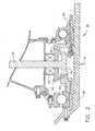
- FIG. 2 illustrates the PTO assembly 38 in more detail.
- the PTO shaft 36 carries an LP bevel gear 44.
- the LP bevel gear 44 engages a complementary LP ring gear 46 which is coupled to the first LP shaft 28A.
- the PTO shaft 36 also carries an HP bevel gear 48, coupled thereto by a one-way clutch 50 of a known type such as a sprag or roller clutch.
- a one-way clutch 50 is oriented so that it permits free rotation of the PTO shaft 36 in a counter-clockwise direction relative to the HP bevel gear 48 and engages or "locks up" to the HP bevel gear when the PTO shaft 36 is rotated in a clockwise direction.
- the HP bevel gear 48 engages a complementary HP ring gear 52 which is coupled to the HP shaft 26.
- the HP shaft 26 rotates in a first direction (for example clockwise as viewed from aft looking forward), while the first LP shaft 28A rotates the opposite direction.
- the HP and LP shafts 26 and 28A "counter-rotate".
- the PTO assembly 38 could also be arranged so as to be useable in an engine having co-rotating high and low pressure shafts (not shown), for example by reversing the orientation of the LP ring gear and moving it aft of the LP bevel gear 44.
- the PTO assembly 38 operates as follows. To start the engine 10, a source of power such as electrical current or compressed air is provided to the starter 42, causing it to turn the PTO shaft 36 in a first direction (clockwise in this example). The clutch 50 engages, causing the HP bevel gear 48 to turn the HP ring gear 52 and thus the HP shaft 26 in a clockwise direction. Simultaneously, the LP bevel gear 44 turns the LP ring gear 46 and thus the first LP shaft 28A in the opposite direction. This rotation of the shafts turns the rear fan 15, booster 16, and compressor 18 to induce an air flow through the engine 10.
- a source of power such as electrical current or compressed air is provided to the starter 42, causing it to turn the PTO shaft 36 in a first direction (clockwise in this example).
- the clutch 50 engages, causing the HP bevel gear 48 to turn the HP ring gear 52 and thus the HP shaft 26 in a clockwise direction.
- the LP bevel gear 44 turns the LP ring gear 46 and thus the first LP
- both the LP and HP shafts 28 and 26 will accelerate well above the starting speed, in opposite directions.
- the HP shaft 26 operates at a substantially higher speed than the LP shaft 28 under substantially all operating conditions.
- the one-way clutch 50 allows the HP shaft 26 to accelerate and rotate free of any load from the PTO shaft 36.
- the first LP shaft 28A transmits torque to the PTO shaft 36 through the LP ring gear 46 and the LP bevel gear 44.
- all of the PTO power requirements are supplied by the first LP shaft 28A.
Landscapes
- Engineering & Computer Science (AREA)
- Chemical & Material Sciences (AREA)
- Combustion & Propulsion (AREA)
- Mechanical Engineering (AREA)
- General Engineering & Computer Science (AREA)
- Gear Transmission (AREA)
- Turbine Rotor Nozzle Sealing (AREA)
Applications Claiming Priority (1)
| Application Number | Priority Date | Filing Date | Title |
|---|---|---|---|
| US11/161,338 US20070022735A1 (en) | 2005-07-29 | 2005-07-29 | Pto assembly for a gas turbine engine |
Publications (2)
| Publication Number | Publication Date |
|---|---|
| EP1748170A2 true EP1748170A2 (de) | 2007-01-31 |
| EP1748170A3 EP1748170A3 (de) | 2011-11-09 |
Family
ID=36922136
Family Applications (1)
| Application Number | Title | Priority Date | Filing Date |
|---|---|---|---|
| EP06253912A Withdrawn EP1748170A3 (de) | 2005-07-29 | 2006-07-27 | Zapfwellenantrieb einer Gasturbine, Gasturbine und verfahren zum Betreiben einer Gasturbine |
Country Status (5)
| Country | Link |
|---|---|
| US (1) | US20070022735A1 (de) |
| EP (1) | EP1748170A3 (de) |
| JP (1) | JP2007040302A (de) |
| CN (1) | CN1904325A (de) |
| CA (1) | CA2553245A1 (de) |
Cited By (4)
| Publication number | Priority date | Publication date | Assignee | Title |
|---|---|---|---|---|
| EP2028352A1 (de) * | 2007-08-23 | 2009-02-25 | Snecma | Gasturbinenmotor mit Antriebsmittel für das Zubehörgehäuse und Montageverfahren für besagten Motor |
| FR3026776A1 (fr) * | 2014-10-03 | 2016-04-08 | Snecma | Dispositif de transmission de puissance pour une turbomachine d'aeronef |
| EP2192291A3 (de) * | 2008-11-28 | 2017-10-18 | Rolls-Royce plc | Starter-Generatoranordnung eines Flugtriebwerks |
| WO2023073305A1 (fr) * | 2021-10-28 | 2023-05-04 | Safran Aircraft Engines | Integration de generatrices dans un flux d'air de reacteur d'avion |
Families Citing this family (71)
| Publication number | Priority date | Publication date | Assignee | Title |
|---|---|---|---|---|
| US7802757B2 (en) * | 2005-11-09 | 2010-09-28 | Pratt & Whitney Canada Corp. | Method and system for taxiing an aircraft |
| US8015828B2 (en) * | 2007-04-03 | 2011-09-13 | General Electric Company | Power take-off system and gas turbine engine assembly including same |
| US8146370B2 (en) * | 2008-05-21 | 2012-04-03 | Honeywell International Inc. | Turbine drive system with lock-up clutch and method |
| US20100005810A1 (en) * | 2008-07-11 | 2010-01-14 | Rob Jarrell | Power transmission among shafts in a turbine engine |
| US8881534B2 (en) * | 2008-12-29 | 2014-11-11 | Rolls-Royce Corporation | Gas turbine engine shaft coupler |
| FR2942273B1 (fr) * | 2009-02-18 | 2011-06-10 | Snecma | Moteur double flux a roues de turbine contrarotatives |
| JP5016706B2 (ja) * | 2009-11-04 | 2012-09-05 | 川崎重工業株式会社 | 航空機用始動発電装置 |
| CA2724611A1 (en) * | 2009-12-21 | 2011-06-21 | General Electric Company | Power extraction system |
| US20110146289A1 (en) * | 2009-12-21 | 2011-06-23 | John Lewis Baughman | Power extraction method |
| US20110146228A1 (en) * | 2009-12-21 | 2011-06-23 | John Lewis Baughman | Power extraction system |
| US8966911B2 (en) * | 2009-12-29 | 2015-03-03 | Rolls-Royce North American Technologies, Inc. | Turbofan engine with HP and LP power off-takes |
| FR2963062B1 (fr) * | 2010-07-20 | 2012-08-31 | Snecma | Assemblage entre un tourillon d'arbre de compresseur et un pignon conique pour l'entrainement d'un boitier d'accessoires d'une turbomachine |
| US8519555B2 (en) | 2010-11-29 | 2013-08-27 | Pratt & Whitney Canada Corp. | Combination low spool generator and ram air turbine generator |
| US9051881B2 (en) | 2010-12-28 | 2015-06-09 | Rolls-Royce Corporation | Electrical power generation and windmill starting for turbine engine and aircraft |
| US9200592B2 (en) * | 2011-06-28 | 2015-12-01 | United Technologies Corporation | Mechanism for turbine engine start from low spool |
| US8723385B2 (en) | 2011-10-07 | 2014-05-13 | General Electric Company | Generator |
| US8723349B2 (en) | 2011-10-07 | 2014-05-13 | General Electric Company | Apparatus for generating power from a turbine engine |
| US9316117B2 (en) | 2012-01-30 | 2016-04-19 | United Technologies Corporation | Internally cooled spoke |
| US20130192191A1 (en) | 2012-01-31 | 2013-08-01 | Frederick M. Schwarz | Gas turbine engine with high speed low pressure turbine section and bearing support features |
| US20150345426A1 (en) | 2012-01-31 | 2015-12-03 | United Technologies Corporation | Geared turbofan gas turbine engine architecture |
| US9222417B2 (en) | 2012-01-31 | 2015-12-29 | United Technologies Corporation | Geared turbofan gas turbine engine architecture |
| US10287914B2 (en) | 2012-01-31 | 2019-05-14 | United Technologies Corporation | Gas turbine engine with high speed low pressure turbine section and bearing support features |
| US20140196472A1 (en) * | 2012-01-31 | 2014-07-17 | United Technologies Corporation | Geared turbofan gas turbine engine architecture |
| US8935913B2 (en) | 2012-01-31 | 2015-01-20 | United Technologies Corporation | Geared turbofan gas turbine engine architecture |
| US8887487B2 (en) | 2012-01-31 | 2014-11-18 | United Technologies Corporation | Geared turbofan gas turbine engine architecture |
| US20130195624A1 (en) * | 2012-01-31 | 2013-08-01 | Frederick M. Schwarz | Geared turbofan engine with counter-rotating shafts |
| US20130219907A1 (en) * | 2012-02-29 | 2013-08-29 | Frederick M. Schwarz | Geared turbofan architecture for improved thrust density |
| US10309232B2 (en) * | 2012-02-29 | 2019-06-04 | United Technologies Corporation | Gas turbine engine with stage dependent material selection for blades and disk |
| US10125693B2 (en) | 2012-04-02 | 2018-11-13 | United Technologies Corporation | Geared turbofan engine with power density range |
| WO2014130148A1 (en) * | 2013-02-24 | 2014-08-28 | Rolls-Royce Corporation | Combined cycle power plant |
| WO2014149101A2 (en) | 2013-03-15 | 2014-09-25 | Rolls-Royce Corporation | Propulsion, electrical, and thermal management device for a small unmanned aerial vehicle |
| RU2689258C2 (ru) * | 2014-04-29 | 2019-05-24 | Сафран Эркрафт Энджинз | Газотурбинная установка и способ ее демонтажа |
| US11808210B2 (en) | 2015-02-12 | 2023-11-07 | Rtx Corporation | Intercooled cooling air with heat exchanger packaging |
| US10731560B2 (en) | 2015-02-12 | 2020-08-04 | Raytheon Technologies Corporation | Intercooled cooling air |
| US10371055B2 (en) | 2015-02-12 | 2019-08-06 | United Technologies Corporation | Intercooled cooling air using cooling compressor as starter |
| US10221862B2 (en) | 2015-04-24 | 2019-03-05 | United Technologies Corporation | Intercooled cooling air tapped from plural locations |
| US10830148B2 (en) | 2015-04-24 | 2020-11-10 | Raytheon Technologies Corporation | Intercooled cooling air with dual pass heat exchanger |
| US10480419B2 (en) | 2015-04-24 | 2019-11-19 | United Technologies Corporation | Intercooled cooling air with plural heat exchangers |
| US10100739B2 (en) | 2015-05-18 | 2018-10-16 | United Technologies Corporation | Cooled cooling air system for a gas turbine engine |
| US10794288B2 (en) | 2015-07-07 | 2020-10-06 | Raytheon Technologies Corporation | Cooled cooling air system for a turbofan engine |
| US10443508B2 (en) | 2015-12-14 | 2019-10-15 | United Technologies Corporation | Intercooled cooling air with auxiliary compressor control |
| CN106907242A (zh) * | 2015-12-22 | 2017-06-30 | 中航商用航空发动机有限责任公司 | 航空发动机叶轮 |
| GB2550397B (en) * | 2016-05-19 | 2018-11-21 | Derwent Aviation Consulting Ltd | A turbo machine comprising a compressor system |
| US10883424B2 (en) | 2016-07-19 | 2021-01-05 | Pratt & Whitney Canada Corp. | Multi-spool gas turbine engine architecture |
| US10669940B2 (en) | 2016-09-19 | 2020-06-02 | Raytheon Technologies Corporation | Gas turbine engine with intercooled cooling air and turbine drive |
| US10794290B2 (en) | 2016-11-08 | 2020-10-06 | Raytheon Technologies Corporation | Intercooled cooled cooling integrated air cycle machine |
| US10550768B2 (en) | 2016-11-08 | 2020-02-04 | United Technologies Corporation | Intercooled cooled cooling integrated air cycle machine |
| RU2644497C1 (ru) * | 2016-11-15 | 2018-02-12 | Публичное акционерное общество "ОДК - Уфимское моторостроительное производственное объединение" (ПАО "ОДК-УМПО") | Единый механизм передачи крутящего момента агрегатам газотурбинного двигателя (варианты) |
| US20180162537A1 (en) * | 2016-12-09 | 2018-06-14 | United Technologies Corporation | Environmental control system air circuit |
| US10961911B2 (en) | 2017-01-17 | 2021-03-30 | Raytheon Technologies Corporation | Injection cooled cooling air system for a gas turbine engine |
| US10995673B2 (en) | 2017-01-19 | 2021-05-04 | Raytheon Technologies Corporation | Gas turbine engine with intercooled cooling air and dual towershaft accessory gearbox |
| US10590853B2 (en) | 2017-01-19 | 2020-03-17 | United Technologies Corporation | Gas turbine engine dual towershaft accessory gearbox assembly with a transmission |
| US10590852B2 (en) | 2017-01-19 | 2020-03-17 | United Technologies Corporation | Gas turbine engine dual towershaft accessory gearbox assembly with a transmission |
| US10422243B2 (en) | 2017-01-19 | 2019-09-24 | United Technologies Corporation | Gas turbine engine dual towershaft accessory gearbox and starter generator assembly |
| US10738709B2 (en) * | 2017-02-09 | 2020-08-11 | Pratt & Whitney Canada Corp. | Multi-spool gas turbine engine |
| US10577964B2 (en) | 2017-03-31 | 2020-03-03 | United Technologies Corporation | Cooled cooling air for blade air seal through outer chamber |
| US10711640B2 (en) | 2017-04-11 | 2020-07-14 | Raytheon Technologies Corporation | Cooled cooling air to blade outer air seal passing through a static vane |
| US10858950B2 (en) | 2017-07-27 | 2020-12-08 | Rolls-Royce North America Technologies, Inc. | Multilayer abradable coatings for high-performance systems |
| US10900371B2 (en) | 2017-07-27 | 2021-01-26 | Rolls-Royce North American Technologies, Inc. | Abradable coatings for high-performance systems |
| WO2019092910A1 (ja) | 2017-11-13 | 2019-05-16 | 株式会社Ihi | ターボファンエンジン |
| US10823081B2 (en) * | 2017-12-21 | 2020-11-03 | Raytheon Technologies Corporation | Concentric power takeoff transmission |
| US10738703B2 (en) | 2018-03-22 | 2020-08-11 | Raytheon Technologies Corporation | Intercooled cooling air with combined features |
| US10808619B2 (en) | 2018-04-19 | 2020-10-20 | Raytheon Technologies Corporation | Intercooled cooling air with advanced cooling system |
| US10830145B2 (en) | 2018-04-19 | 2020-11-10 | Raytheon Technologies Corporation | Intercooled cooling air fleet management system |
| US10718233B2 (en) | 2018-06-19 | 2020-07-21 | Raytheon Technologies Corporation | Intercooled cooling air with low temperature bearing compartment air |
| US10954865B2 (en) * | 2018-06-19 | 2021-03-23 | The Boeing Company | Pressurized air systems for aircraft and related methods |
| US11255268B2 (en) | 2018-07-31 | 2022-02-22 | Raytheon Technologies Corporation | Intercooled cooling air with selective pressure dump |
| FR3089585B1 (fr) * | 2018-12-07 | 2021-09-17 | Safran Helicopter Engines | Rotor de turbomachine |
| GB201915015D0 (en) * | 2019-10-17 | 2019-12-04 | Rolls Royce Plc | Gas turbine engine |
| US12388322B2 (en) | 2023-03-24 | 2025-08-12 | Rolls-Royce North American Technologies, Inc. | Electric generator behind fan in turbine engine |
| US20250109712A1 (en) * | 2023-09-29 | 2025-04-03 | Rtx Corporation | Selective power distribution for an aircraft propulsion system |
Family Cites Families (17)
| Publication number | Priority date | Publication date | Assignee | Title |
|---|---|---|---|---|
| US2613749A (en) * | 1948-08-14 | 1952-10-14 | Lockheed Aircraft Corp | Gas turbine power plant having propeller drive |
| US2838913A (en) * | 1950-07-15 | 1958-06-17 | Gen Motors Corp | Aircraft power system and clutch control therefor |
| US2952973A (en) * | 1958-06-02 | 1960-09-20 | Gen Motors Corp | Turbofan-ramjet engine |
| US3100378A (en) * | 1960-11-14 | 1963-08-13 | Avco Corp | Auxiliary power drive mechanism for a gas turbine engine |
| GB1072485A (en) * | 1963-05-03 | 1967-06-14 | Plessey Uk Ltd | Improvements in or relating to engine-starter and auxiliary drive systems |
| US3688560A (en) * | 1971-01-29 | 1972-09-05 | Gen Electric | Gas turbine engine with improved auxiliary power take-off |
| US3907386A (en) * | 1973-01-22 | 1975-09-23 | Avco Corp | Bearing assembly systems |
| DE3622022A1 (de) * | 1986-07-01 | 1988-01-07 | Kloeckner Humboldt Deutz Ag | Gasturbinentriebwerk |
| US4936748A (en) * | 1988-11-28 | 1990-06-26 | General Electric Company | Auxiliary power source in an unducted fan gas turbine engine |
| GB2229237B (en) * | 1989-03-14 | 1993-01-20 | Rolls Royce Plc | Differential gear assembly |
| US5081832A (en) * | 1990-03-05 | 1992-01-21 | Rolf Jan Mowill | High efficiency, twin spool, radial-high pressure, gas turbine engine |
| US5237817A (en) * | 1992-02-19 | 1993-08-24 | Sundstrand Corporation | Gas turbine engine having low cost speed reduction drive |
| US5349814A (en) * | 1993-02-03 | 1994-09-27 | General Electric Company | Air-start assembly and method |
| US5845483A (en) * | 1996-04-10 | 1998-12-08 | General Electric Company | Windmill engine starting system with fluid driven motor and pump |
| JP2001317377A (ja) * | 2000-04-28 | 2001-11-16 | Honda Motor Co Ltd | ガスタービンエンジンの補機駆動ユニット |
| FR2826052B1 (fr) * | 2001-06-19 | 2003-12-19 | Snecma Moteurs | Dispositif de secours au rallumage d'un turboreacteur en autorotation |
| US20070199331A1 (en) * | 2003-09-19 | 2007-08-30 | Maguire Alan R | Power transmission arrangement |
-
2005
- 2005-07-29 US US11/161,338 patent/US20070022735A1/en not_active Abandoned
-
2006
- 2006-07-20 CA CA002553245A patent/CA2553245A1/en not_active Abandoned
- 2006-07-27 EP EP06253912A patent/EP1748170A3/de not_active Withdrawn
- 2006-07-28 JP JP2006206054A patent/JP2007040302A/ja active Pending
- 2006-07-31 CN CNA2006101100483A patent/CN1904325A/zh active Pending
Cited By (8)
| Publication number | Priority date | Publication date | Assignee | Title |
|---|---|---|---|---|
| EP2028352A1 (de) * | 2007-08-23 | 2009-02-25 | Snecma | Gasturbinenmotor mit Antriebsmittel für das Zubehörgehäuse und Montageverfahren für besagten Motor |
| FR2920191A1 (fr) * | 2007-08-23 | 2009-02-27 | Snecma Sa | Moteur a turbine a gaz avec moyen d'entrainement pour le boitier d'accessoires et procede de montage dudit moteur |
| US8074455B2 (en) | 2007-08-23 | 2011-12-13 | Snecma | Gas turbine engine with a means of driving the accessory gear box, and method of fitting said engine |
| EP2192291A3 (de) * | 2008-11-28 | 2017-10-18 | Rolls-Royce plc | Starter-Generatoranordnung eines Flugtriebwerks |
| FR3026776A1 (fr) * | 2014-10-03 | 2016-04-08 | Snecma | Dispositif de transmission de puissance pour une turbomachine d'aeronef |
| WO2023073305A1 (fr) * | 2021-10-28 | 2023-05-04 | Safran Aircraft Engines | Integration de generatrices dans un flux d'air de reacteur d'avion |
| FR3128734A1 (fr) * | 2021-10-28 | 2023-05-05 | Safran Aircraft Engines | Intégration de génératrices dans un flux d’air de réacteur d’avion |
| US12286887B2 (en) | 2021-10-28 | 2025-04-29 | Safran Aircraft Engines | Integration of generators in an air flow of an aircraft engine |
Also Published As
| Publication number | Publication date |
|---|---|
| JP2007040302A (ja) | 2007-02-15 |
| CA2553245A1 (en) | 2007-01-29 |
| US20070022735A1 (en) | 2007-02-01 |
| EP1748170A3 (de) | 2011-11-09 |
| CN1904325A (zh) | 2007-01-31 |
Similar Documents
| Publication | Publication Date | Title |
|---|---|---|
| EP1748170A2 (de) | Zapfwellenantrieb einer Gasturbine, Gasturbine und verfahren zum Betreiben einer Gasturbine | |
| US10738709B2 (en) | Multi-spool gas turbine engine | |
| US11248532B2 (en) | Hybrid electric dual spool power extraction gearbox | |
| US11686253B2 (en) | Through-flow gas turbine engine with electric motor and electric generator | |
| CA2602325C (en) | Gas turbine engine assembly and method of assembling same | |
| US10422243B2 (en) | Gas turbine engine dual towershaft accessory gearbox and starter generator assembly | |
| US8314505B2 (en) | Gas turbine engine apparatus | |
| EP3987166B1 (de) | Getriebe für einen turbinenmotor mit verstärkungswelle | |
| US7418821B2 (en) | Aircraft gas turbine engines | |
| US11624319B2 (en) | Reverse-flow gas turbine engine with electric motor | |
| EP3904657B1 (de) | Hybride verstärkung von hochdruckwellenbetrieb über niederdruckwellenleistungsextraktion und antrieb von einem differenzialgetriebegenerator | |
| WO2008044973A1 (en) | A device for and a method of starting a gas turbine engine | |
| US12116899B2 (en) | Variable speed pumping system with electric pump motor generator |
Legal Events
| Date | Code | Title | Description |
|---|---|---|---|
| PUAI | Public reference made under article 153(3) epc to a published international application that has entered the european phase |
Free format text: ORIGINAL CODE: 0009012 |
|
| AK | Designated contracting states |
Kind code of ref document: A2 Designated state(s): AT BE BG CH CY CZ DE DK EE ES FI FR GB GR HU IE IS IT LI LT LU LV MC NL PL PT RO SE SI SK TR |
|
| AX | Request for extension of the european patent |
Extension state: AL BA HR MK YU |
|
| PUAL | Search report despatched |
Free format text: ORIGINAL CODE: 0009013 |
|
| AK | Designated contracting states |
Kind code of ref document: A3 Designated state(s): AT BE BG CH CY CZ DE DK EE ES FI FR GB GR HU IE IS IT LI LT LU LV MC NL PL PT RO SE SI SK TR |
|
| AX | Request for extension of the european patent |
Extension state: AL BA HR MK RS |
|
| RIC1 | Information provided on ipc code assigned before grant |
Ipc: F02C 7/32 20060101ALI20111005BHEP Ipc: F02K 3/04 20060101ALI20111005BHEP Ipc: F02C 7/275 20060101ALI20111005BHEP Ipc: F02C 7/36 20060101AFI20111005BHEP |
|
| AKY | No designation fees paid | ||
| REG | Reference to a national code |
Ref country code: DE Ref legal event code: R108 |
|
| STAA | Information on the status of an ep patent application or granted ep patent |
Free format text: STATUS: THE APPLICATION IS DEEMED TO BE WITHDRAWN |
|
| 18D | Application deemed to be withdrawn |
Effective date: 20120201 |
|
| REG | Reference to a national code |
Ref country code: DE Ref legal event code: R108 Effective date: 20120718 |