EP1748172A2 - Régulateur pour un moteur à combustion interne - Google Patents
Régulateur pour un moteur à combustion interne Download PDFInfo
- Publication number
- EP1748172A2 EP1748172A2 EP06015481A EP06015481A EP1748172A2 EP 1748172 A2 EP1748172 A2 EP 1748172A2 EP 06015481 A EP06015481 A EP 06015481A EP 06015481 A EP06015481 A EP 06015481A EP 1748172 A2 EP1748172 A2 EP 1748172A2
- Authority
- EP
- European Patent Office
- Prior art keywords
- internal combustion
- combustion engine
- torque
- motor
- controller
- Prior art date
- Legal status (The legal status is an assumption and is not a legal conclusion. Google has not performed a legal analysis and makes no representation as to the accuracy of the status listed.)
- Withdrawn
Links
Images




Classifications
-
- F—MECHANICAL ENGINEERING; LIGHTING; HEATING; WEAPONS; BLASTING
- F02—COMBUSTION ENGINES; HOT-GAS OR COMBUSTION-PRODUCT ENGINE PLANTS
- F02N—STARTING OF COMBUSTION ENGINES; STARTING AIDS FOR SUCH ENGINES, NOT OTHERWISE PROVIDED FOR
- F02N19/00—Starting aids for combustion engines, not otherwise provided for
-
- F—MECHANICAL ENGINEERING; LIGHTING; HEATING; WEAPONS; BLASTING
- F02—COMBUSTION ENGINES; HOT-GAS OR COMBUSTION-PRODUCT ENGINE PLANTS
- F02D—CONTROLLING COMBUSTION ENGINES
- F02D29/00—Controlling engines, such controlling being peculiar to the devices driven thereby, the devices being other than parts or accessories essential to engine operation, e.g. controlling of engines by signals external thereto
- F02D29/02—Controlling engines, such controlling being peculiar to the devices driven thereby, the devices being other than parts or accessories essential to engine operation, e.g. controlling of engines by signals external thereto peculiar to engines driving vehicles; peculiar to engines driving variable pitch propellers
-
- F—MECHANICAL ENGINEERING; LIGHTING; HEATING; WEAPONS; BLASTING
- F01—MACHINES OR ENGINES IN GENERAL; ENGINE PLANTS IN GENERAL; STEAM ENGINES
- F01N—GAS-FLOW SILENCERS OR EXHAUST APPARATUS FOR MACHINES OR ENGINES IN GENERAL; GAS-FLOW SILENCERS OR EXHAUST APPARATUS FOR INTERNAL-COMBUSTION ENGINES
- F01N3/00—Exhaust or silencing apparatus having means for purifying, rendering innocuous, or otherwise treating exhaust
- F01N3/08—Exhaust or silencing apparatus having means for purifying, rendering innocuous, or otherwise treating exhaust for rendering innocuous
- F01N3/10—Exhaust or silencing apparatus having means for purifying, rendering innocuous, or otherwise treating exhaust for rendering innocuous by thermal or catalytic conversion of noxious components of exhaust
- F01N3/24—Exhaust or silencing apparatus having means for purifying, rendering innocuous, or otherwise treating exhaust for rendering innocuous by thermal or catalytic conversion of noxious components of exhaust characterised by constructional aspects of converting apparatus
-
- F—MECHANICAL ENGINEERING; LIGHTING; HEATING; WEAPONS; BLASTING
- F02—COMBUSTION ENGINES; HOT-GAS OR COMBUSTION-PRODUCT ENGINE PLANTS
- F02D—CONTROLLING COMBUSTION ENGINES
- F02D41/00—Electrical control of supply of combustible mixture or its constituents
- F02D41/02—Circuit arrangements for generating control signals
- F02D41/021—Introducing corrections for particular conditions exterior to the engine
- F02D41/0235—Introducing corrections for particular conditions exterior to the engine in relation with the state of the exhaust gas treating apparatus
-
- F—MECHANICAL ENGINEERING; LIGHTING; HEATING; WEAPONS; BLASTING
- F02—COMBUSTION ENGINES; HOT-GAS OR COMBUSTION-PRODUCT ENGINE PLANTS
- F02D—CONTROLLING COMBUSTION ENGINES
- F02D41/00—Electrical control of supply of combustible mixture or its constituents
- F02D41/02—Circuit arrangements for generating control signals
- F02D41/04—Introducing corrections for particular operating conditions
- F02D41/06—Introducing corrections for particular operating conditions for engine starting or warming up
-
- F—MECHANICAL ENGINEERING; LIGHTING; HEATING; WEAPONS; BLASTING
- F02—COMBUSTION ENGINES; HOT-GAS OR COMBUSTION-PRODUCT ENGINE PLANTS
- F02D—CONTROLLING COMBUSTION ENGINES
- F02D41/00—Electrical control of supply of combustible mixture or its constituents
- F02D41/02—Circuit arrangements for generating control signals
- F02D41/04—Introducing corrections for particular operating conditions
- F02D41/06—Introducing corrections for particular operating conditions for engine starting or warming up
- F02D41/062—Introducing corrections for particular operating conditions for engine starting or warming up for starting
- F02D41/065—Introducing corrections for particular operating conditions for engine starting or warming up for starting at hot start or restart
-
- F—MECHANICAL ENGINEERING; LIGHTING; HEATING; WEAPONS; BLASTING
- F02—COMBUSTION ENGINES; HOT-GAS OR COMBUSTION-PRODUCT ENGINE PLANTS
- F02N—STARTING OF COMBUSTION ENGINES; STARTING AIDS FOR SUCH ENGINES, NOT OTHERWISE PROVIDED FOR
- F02N11/00—Starting of engines by means of electric motors
-
- F—MECHANICAL ENGINEERING; LIGHTING; HEATING; WEAPONS; BLASTING
- F02—COMBUSTION ENGINES; HOT-GAS OR COMBUSTION-PRODUCT ENGINE PLANTS
- F02N—STARTING OF COMBUSTION ENGINES; STARTING AIDS FOR SUCH ENGINES, NOT OTHERWISE PROVIDED FOR
- F02N11/00—Starting of engines by means of electric motors
- F02N11/08—Circuits specially adapted for starting of engines
- F02N11/0814—Circuits specially adapted for starting of engines comprising means for controlling automatic idle-start-stop
- F02N11/0818—Conditions for starting or stopping the engine or for deactivating the idle-start-stop mode
-
- F—MECHANICAL ENGINEERING; LIGHTING; HEATING; WEAPONS; BLASTING
- F02—COMBUSTION ENGINES; HOT-GAS OR COMBUSTION-PRODUCT ENGINE PLANTS
- F02N—STARTING OF COMBUSTION ENGINES; STARTING AIDS FOR SUCH ENGINES, NOT OTHERWISE PROVIDED FOR
- F02N11/00—Starting of engines by means of electric motors
- F02N11/08—Circuits specially adapted for starting of engines
- F02N11/0814—Circuits specially adapted for starting of engines comprising means for controlling automatic idle-start-stop
- F02N11/0818—Conditions for starting or stopping the engine or for deactivating the idle-start-stop mode
- F02N11/0833—Vehicle conditions
- F02N11/084—State of vehicle accessories, e.g. air condition or power steering
-
- F—MECHANICAL ENGINEERING; LIGHTING; HEATING; WEAPONS; BLASTING
- F02—COMBUSTION ENGINES; HOT-GAS OR COMBUSTION-PRODUCT ENGINE PLANTS
- F02N—STARTING OF COMBUSTION ENGINES; STARTING AIDS FOR SUCH ENGINES, NOT OTHERWISE PROVIDED FOR
- F02N99/00—Subject matter not provided for in the other groups of this subclass
- F02N99/002—Starting combustion engines by ignition means
- F02N99/006—Providing a combustible mixture inside the cylinder
-
- F—MECHANICAL ENGINEERING; LIGHTING; HEATING; WEAPONS; BLASTING
- F02—COMBUSTION ENGINES; HOT-GAS OR COMBUSTION-PRODUCT ENGINE PLANTS
- F02D—CONTROLLING COMBUSTION ENGINES
- F02D2200/00—Input parameters for engine control
- F02D2200/02—Input parameters for engine control the parameters being related to the engine
- F02D2200/06—Fuel or fuel supply system parameters
- F02D2200/0602—Fuel pressure
-
- F—MECHANICAL ENGINEERING; LIGHTING; HEATING; WEAPONS; BLASTING
- F02—COMBUSTION ENGINES; HOT-GAS OR COMBUSTION-PRODUCT ENGINE PLANTS
- F02D—CONTROLLING COMBUSTION ENGINES
- F02D2200/00—Input parameters for engine control
- F02D2200/02—Input parameters for engine control the parameters being related to the engine
- F02D2200/08—Exhaust gas treatment apparatus parameters
- F02D2200/0802—Temperature of the exhaust gas treatment apparatus
-
- F—MECHANICAL ENGINEERING; LIGHTING; HEATING; WEAPONS; BLASTING
- F02—COMBUSTION ENGINES; HOT-GAS OR COMBUSTION-PRODUCT ENGINE PLANTS
- F02D—CONTROLLING COMBUSTION ENGINES
- F02D2200/00—Input parameters for engine control
- F02D2200/02—Input parameters for engine control the parameters being related to the engine
- F02D2200/08—Exhaust gas treatment apparatus parameters
- F02D2200/0814—Oxygen storage amount
-
- F—MECHANICAL ENGINEERING; LIGHTING; HEATING; WEAPONS; BLASTING
- F02—COMBUSTION ENGINES; HOT-GAS OR COMBUSTION-PRODUCT ENGINE PLANTS
- F02D—CONTROLLING COMBUSTION ENGINES
- F02D37/00—Non-electrical conjoint control of two or more functions of engines, not otherwise provided for
- F02D37/02—Non-electrical conjoint control of two or more functions of engines, not otherwise provided for one of the functions being ignition
-
- F—MECHANICAL ENGINEERING; LIGHTING; HEATING; WEAPONS; BLASTING
- F02—COMBUSTION ENGINES; HOT-GAS OR COMBUSTION-PRODUCT ENGINE PLANTS
- F02N—STARTING OF COMBUSTION ENGINES; STARTING AIDS FOR SUCH ENGINES, NOT OTHERWISE PROVIDED FOR
- F02N2200/00—Parameters used for control of starting apparatus
- F02N2200/08—Parameters used for control of starting apparatus said parameters being related to the vehicle or its components
- F02N2200/0806—Air condition state
-
- F—MECHANICAL ENGINEERING; LIGHTING; HEATING; WEAPONS; BLASTING
- F02—COMBUSTION ENGINES; HOT-GAS OR COMBUSTION-PRODUCT ENGINE PLANTS
- F02N—STARTING OF COMBUSTION ENGINES; STARTING AIDS FOR SUCH ENGINES, NOT OTHERWISE PROVIDED FOR
- F02N2200/00—Parameters used for control of starting apparatus
- F02N2200/08—Parameters used for control of starting apparatus said parameters being related to the vehicle or its components
- F02N2200/0807—Brake booster state
-
- F—MECHANICAL ENGINEERING; LIGHTING; HEATING; WEAPONS; BLASTING
- F02—COMBUSTION ENGINES; HOT-GAS OR COMBUSTION-PRODUCT ENGINE PLANTS
- F02N—STARTING OF COMBUSTION ENGINES; STARTING AIDS FOR SUCH ENGINES, NOT OTHERWISE PROVIDED FOR
- F02N2200/00—Parameters used for control of starting apparatus
- F02N2200/08—Parameters used for control of starting apparatus said parameters being related to the vehicle or its components
- F02N2200/0809—Electrical loads
-
- F—MECHANICAL ENGINEERING; LIGHTING; HEATING; WEAPONS; BLASTING
- F02—COMBUSTION ENGINES; HOT-GAS OR COMBUSTION-PRODUCT ENGINE PLANTS
- F02N—STARTING OF COMBUSTION ENGINES; STARTING AIDS FOR SUCH ENGINES, NOT OTHERWISE PROVIDED FOR
- F02N2200/00—Parameters used for control of starting apparatus
- F02N2200/12—Parameters used for control of starting apparatus said parameters being related to the vehicle exterior
- F02N2200/122—Atmospheric temperature
-
- F—MECHANICAL ENGINEERING; LIGHTING; HEATING; WEAPONS; BLASTING
- F02—COMBUSTION ENGINES; HOT-GAS OR COMBUSTION-PRODUCT ENGINE PLANTS
- F02N—STARTING OF COMBUSTION ENGINES; STARTING AIDS FOR SUCH ENGINES, NOT OTHERWISE PROVIDED FOR
- F02N2300/00—Control related aspects of engine starting
- F02N2300/10—Control related aspects of engine starting characterised by the control output, i.e. means or parameters used as a control output or target
- F02N2300/104—Control of the starter motor torque
-
- F—MECHANICAL ENGINEERING; LIGHTING; HEATING; WEAPONS; BLASTING
- F02—COMBUSTION ENGINES; HOT-GAS OR COMBUSTION-PRODUCT ENGINE PLANTS
- F02N—STARTING OF COMBUSTION ENGINES; STARTING AIDS FOR SUCH ENGINES, NOT OTHERWISE PROVIDED FOR
- F02N2300/00—Control related aspects of engine starting
- F02N2300/20—Control related aspects of engine starting characterised by the control method
- F02N2300/2002—Control related aspects of engine starting characterised by the control method using different starting modes, methods, or actuators depending on circumstances, e.g. engine temperature or component wear
-
- Y—GENERAL TAGGING OF NEW TECHNOLOGICAL DEVELOPMENTS; GENERAL TAGGING OF CROSS-SECTIONAL TECHNOLOGIES SPANNING OVER SEVERAL SECTIONS OF THE IPC; TECHNICAL SUBJECTS COVERED BY FORMER USPC CROSS-REFERENCE ART COLLECTIONS [XRACs] AND DIGESTS
- Y02—TECHNOLOGIES OR APPLICATIONS FOR MITIGATION OR ADAPTATION AGAINST CLIMATE CHANGE
- Y02T—CLIMATE CHANGE MITIGATION TECHNOLOGIES RELATED TO TRANSPORTATION
- Y02T10/00—Road transport of goods or passengers
- Y02T10/10—Internal combustion engine [ICE] based vehicles
- Y02T10/40—Engine management systems
Definitions
- the invention relates to a controller for an internal combustion engine, particularly to a controller for an internal combustion engine for controlling a restart of the internal combustion engine for an idling stop.
- an idling stop system for restarting the internal combustion engine by cranking the internal combustion engine up with a starter motor or the like a great amount of electric power is required for the cranking up to cause a provability of that a lack in electric power of a battery electric power source occurs to prevent temporarily an electric load from being activated when restarting. Further, a load to the battery is great to accelerate a deterioration of the battery.
- a start of the internal combustion engine is resolved by a total amount of a torque generated by the combustion of the internal combustion engine and the rotational torque (start assisting amount) of the motor, and the internal combustion engine can be started when the total amount exceeds a predetermined value.
- the invention is based on the above problem, and an object of the invention is to provide a controller of the internal combustion engine satisfying both of the reduction in the exhaust gas and the starting performance, and realizing the restarting optimized in a consumed energy.
- a controller for an internal combustion engine may include a motor for applying a rotational torque to a crank shaft so that the internal combustion engine may be brought into action, according to the invention, may comprise: an exhaust emission purifier (catalyst, or three way catalyst) condition detecting means for detecting a condition of an exhaust emission purifier (catalyst, or three way catalyst) which may be arranged on an exhaust pipe of the internal combustion engine, and/or a start-up assist controlling means for determining a start-up assisting degree of the motor on the basis of the condition of the exhaust emission purifier (catalyst) which may be detected by the exhaust emission purifier condition detecting means (catalyst condition detecting means) when the internal combustion engine may be restarted.
- an exhaust emission purifier catalyst, or three way catalyst
- condition detecting means for detecting a condition of an exhaust emission purifier (catalyst, or three way catalyst) which may be arranged on an exhaust pipe of the internal combustion engine
- start-up assist controlling means for
- a controller for the internal combustion engine may include the motor for applying the rotational torque to the crank shaft so that the internal combustion engine may be brought into action, according to the invention, may comprise: an air-fuel ratio adjusting means for adjusting an air-fuel ratio of the internal combustion engine, the exhaust emission purifier condition detecting means for detecting the condition of the exhaust emission purifier which may be arranged on the exhaust pipe of the internal combustion engine, and/or a start-up assist controlling means for determining the air-fuel ratio on the basis of the condition of the exhaust emission purifier which may be detected by the exhaust emission purifier condition detecting means and/or determining a start-up assisting degree of the motor on the basis of the air-fuel ratio, when the internal combustion engine may be restarted.
- a controller for the internal combustion engine may include the motor for applying the rotational torque to the crank shaft so that the internal combustion engine may be brought into action, according to the invention, may comprise: an ignition timing adjusting means for adjusting an ignition timing of the internal combustion engine, the exhaust emission purifier condition detecting means for detecting the condition of the exhaust emission purifier which may be arranged on the exhaust pipe of the internal combustion engine, and/or a start-up assist controlling means for determining the ignition timing on the basis of the condition of the exhaust emission purifier detected by the exhaust emission purifier condition detecting means and/or determining a start-up assisting degree of the motor on the basis of the ignition timing, when the internal combustion engine may be restarted.
- the exhaust emission purifier condition detecting means may preferably detect at least one of an oxygen storage (degree) of the exhaust emission purifier and/or a temperature of the exhaust emission purifier.
- the start-up assisting degree of the motor which may be determined by the start-up assist controlling means may preferably be at least one of a torque generated by the motor and/or a time period during which the torque may be generated by the motor.
- the internal combustion engine may preferably have a fuel supply means (fuel feed means) capable of injecting a fuel directly into a combustion chamber of the internal combustion engine, and/or the fuel may be injected into an engine cylinder in an expansion and/or compression stroke of the internal combustion engine.
- a fuel supply means fuel feed means
- the start-up assist controlling means may compensate preferably the start-up assisting degree on the basis of a time period in which the engine may be stopped, a cooling water temperature of the engine.
- the start-up assist controlling means may compensate the start-up assisting degree on the basis of a position of the crank at which the internal combustion engine may be stopped.
- the start-up assisting degree of the motor may be determined on the basis of the condition of the exhaust emission purifier of the internal combustion engine, a starter for optimizing an energy consumed for the starting with improving the characteristic of the exhaust gas of the internal combustion engine when being started and/or making a start-up performance constant, is realized.
- a torque for starting the internal combustion engine is optimized for minimum start-up assist, an electric power is prevented from being consumed excessively to improve a fuel consumption and to decrease a load to an electric source of the battery or the like for the motor.
- a controller for starting up an internal combustion engine may include a catalyst for purifying an exhaust gas of the internal combustion engine, and/or a rotational shaft capable of being rotationally driven by a combustion torque generated by a combustion in the internal combustion engine and/or by a motor torque generated by a motor so that the combustion may be started up and/or continued, may comprise:
- the motor controller determines the at least one of the value of the motor torque and/or the time period before at least one of a fuel injection and/or an ignition is restarted after the at least one of the fuel injection and/or the ignition is stopped, a change in condition causing the significant variation of the combustion torque or torque loss occurring before at least one of a fuel injection and/or an ignition is restarted after the at least one of the fuel injection and/or the ignition is stopped, can be taken into consideration for preventing the output of the motor from being excessive and insufficient.
- the value of the combustion torque may be estimated from at least one of the air-fuel ratio for starting up the internal combustion engine, the ignition timing for starting up the internal combustion engine, a time period during which the internal combustion engine is stopped before being restarted, a rotational position of the rotational shaft of stoppage before the internal combustion engine is started up, a temperature of the internal combustion engine of stoppage before the internal combustion engine is started up, a temperature of the catalyst measured before at least one of a fuel injection and/or an ignition is restarted after the fuel injection and/or the ignition are stopped and/or a concentration of at least one of HC, CO and NOx included by the exhaust gas discharged from the catalyst before the internal combustion engine is stopped to be restarted along at least one of a theoretically or experimentally predetermined relationship between the air-fuel ratio and the combustion torque, a theoretically or experimentally predetermined relationship between the ignition timing and the combustion torque, a theoretically or experimentally predetermined relationship between the time period and the combustion torque, a theoretically or experimentally predetermined relationship between the rotational position and
- the torque loss may be estimated from at least one of a temperature of the internal combustion engine of stoppage before the internal combustion engine is started up and/or a gradient in decreasing velocity of the rotational shaft after the fuel injection and ignition are stopped before the internal combustion engine is started up along at least one a theoretically or experimentally predetermined relationship between the torque loss and the temperature of the internal combustion engine of stoppage and/or a theoretically or experimentally predetermined relationship between the torque loss and the gradient in decreasing velocity of the rotational shaft corresponding to the at least one of the temperature of the internal combustion engine and/or the gradient in decreasing velocity of the rotational shaft.
- At least one of the air-fuel ratio and ignition timing for starting up the internal combustion engine may be determined from at least one of a temperature of the catalyst measured before at least one of a fuel injection and/or an ignition is restarted after the fuel injection and/or the ignition are stopped and/or a concentration of at least one of HC, CO and NOx included by the exhaust gas discharged from the catalyst before the internal combustion engine is stopped to be restarted along at least one of a theoretically or experimentally predetermined relationship between the at least one of the air-fuel ratio and/or ignition timing for starting up the internal combustion engine and/or the temperature of the catalyst and/or a theoretically or experimentally predetermined relationship between the at least one of the air-fuel ratio and/or ignition timing for starting up the internal combustion engine and/or the concentration corresponding to the at least one of the temperature of the catalyst and/or the concentration.
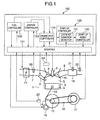
- Fig. 1 is a view showing a whole of an internal combustion engine to which an embodiment (embodiment 1) of a controller for the internal combustion engine of the invention is applied.
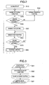
- Fig. 2 is a flow chart showing briefly a sequential control from a start to a stoppage by the controller for the internal combustion engine in fig. 1.
- Fig. 3 is a flow chart showing in detail a start-up control in the embodiment 1 in fig. 1.
- Fig. 4 is a view showing a whole of an internal combustion engine to which an embodiment (embodiment 2) of a controller for the internal combustion engine of the invention is applied.
- Fig. 5 is a flow chart showing in detail a start-up control in the embodiment 2 in fig. 4.
- Fig. 6 is a view showing a relationship between an air-fuel ratio on start-up and a torque generated by combustion.
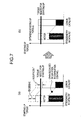
- Figs. 7a and 7b are diagrams showing relationships between the torque generated by combustion and a motor torque in accordance with a variation in condition of catalyst.
- Fig. 8 is a block diagram showing in detail a start-up assist controller of the embodiment 1 in fig. 1.
- Fig. 9 is a block diagram showing in detail a start-up assist controller of the embodiment 2 in fig. 4.
- Fig. 1 is a view showing a whole of structure of an internal combustion engine having the controller as the embodiment of the invention, and the internal combustion engine 1 as, for example, a four-cycle engine to be mounted on an automobile, has a plurality of cylinders 2.
- fig. 1 shows only one of the cylinders 2, but the other ones of the cylinders 2 has a common structure.
- the internal combustion engine 1 is occasionally called as the engine 1.
- a number of the cylinders 2 of the internal combustion engine 1 is, 3, 4, 6 or 8, to be called as 3 cylinders, 4 cylinders, 6 cylinders or 8 cylinders.
- a piston 3 is arranged in the cylinder 2 to cooperate with the cylinder 2 to define a combustion chamber 5.
- a fuel is injected directly into the combustion chamber 5 from a fuel injection valve 4 for each of the cylinders to constitute an internal combustion engine of cylinder injection of fuel in which a mixture of the injected fuel and an air in the combustion chamber is ignited by an ignition plug 6.
- the fuel injection valve 4 may be mounted on an intake air pipe 7 so that the fuel and the air are mixed with each other before being taken into the combustion chamber 5.
- the internal combustion engine 1 has a connecting rod 13 and a crank arm 14 to transmit a reciprocal movement of the piston 3 as a rotational movement of a crank shaft 12.
- the internal combustion engine 1 has an intake air valve 9 for opening and closing a communication between the combustion chamber 5 and the intake air pipe 7 and an exhaust valve 10 for opening and closing a communication between the combustion chamber 5 and an exhaust pipe 8.
- a throttle valve 11 of electrically controlled type for adjusting a flow rate of an intake air and an intake air flow rare sensor 20 for measuring the flow (rate) of the intake air are arranged on the intake air pipe 7.
- the internal combustion engine 1 has a starter motor 15 for rotationally driving the crank shaft 12 through a not-shown gear mechanism from an outside.
- the starter motor 15 may controlled in accordance with a supplied electric current controlled to adjust a velocity of rotation (cranking) of the crank shaft 12 or voltage or in accordance with on-off control of supplied energy as well known without controlling the electric current or voltage.
- a motor 17 for transmitting the rotational energy to the crank shaft 12 through, for example, a belt mechanism, may be arranged around the crank shaft 12.
- the internal combustion engine 1 has a crank angle sensor 23 for outputting a signal corresponding to a rotational angle of the crank shaft, and a water temperature sensor for outputting a signal corresponding to an engine cooling water temperature.
- the crank angle sensor 23 is preferably capable of measuring the rotational angle of each of a rotational direction of the crank shaft 12 and a reverse rotational direction thereof as a resolver used for rotational control of the motor.
- an engine control unit (ECU) 100 As a controller for the internal combustion engine, an engine control unit (ECU) 100 is arranged.
- the ECU 100 is a microcomputer type including a microprocessor and peripheral devices such as RAM, ROM (not shown) and so force.
- the ECU 100 receives the sensor signals through the interface 101 from the intake-air flow (rate) sensor 20, catalyst temperature sensor 21, air-fuel ratio sensor 22, crank angle sensor 23 and water temperature sensor 24 to perform various treatments for controlling an operating condition of the internal combustion engine along a computer program recorded in the ROM.
- the ECU 100 has, as basic components thereof, the interface 101, fuel controller 102 and ignition controller 103.
- the fuel controller 102 adjusts a fuel injection rate of the fuel injection valve 4 on the basis of the intake-air flow rate measured by the intake-air flow (rate) sensor 20 and the engine rotational speed calculated from the crank angle measured by the crank angle sensor 23 so that the air-fuel ratio measured by the air-fuel sensor 22 arranged on the exhaust pipe 8 becomes a predetermined air-fuel ratio.
- the ignition controller 103 adjusts the ignition timing of the ignition plug 6.
- the ECU 100 has the stoppage controller 110 for controlling the idling stop as well as an automatic restart, and the star-up controller 120.
- the interface 101 performs for the idling stop control, an input process for taking into the ECU the signals from the sensors for detecting the conditions required for starting, stopping and operating the internal combustion engine, and an output process for controlling and driving the fuel injection valve 4, ignition plug 6, throttle valve 11, starter motor 15, motor 17 and so forth required for starting, stopping and operating the internal combustion engine.
- the stoppage controller 110 controls the stoppage of the internal combustion engine on the basis of ordered values for the fuel injection valve 4, ignition plug 6 and throttle valve 11 by the fuel controller 102 and ignition controller 103.
- the star-up controller (restart controller) 120 calculates, when the internal combustion engine 1 is started up (restarted), the ordered values for the fuel injection valve 4, ignition plug 6 and throttle valve 11 to control the combustion of the internal combustion engine 1, calculates ordered values for the starter motor 15 and motor 17 to control a start-up assisting value, and has the catalyst condition detector 121 and start-up assist controller 122.
- the catalyst condition detector 121 detects an exhaust gas purifying performance by detecting an activated condition of the catalyst 18 and an ambience in the catalyst on the basis of the signals of the catalyst temperature sensor 21 and the air-fuel ratio sensor 22, or estimates the exhaust gas purifying performance with estimating the activated condition of the catalyst 18 and the ambience in the catalyst from an operating condition of the internal combustion engine 1.
- the start-up assist controller 122 calculates the start-up assisting degree to order the starter motor 15 or the motor 17 on the basis of the condition of the catalyst detected by the catalyst condition detector 121. That is, the start-up assist controller 122 determines the start-up assisting degree of the starter motor 15 or the motor 17 on the basis of the condition of the catalyst.
- the start and stoppage of the internal combustion engine 1 are carried out by the start-up controller 120 and the stoppage controller 110 in the ECU. Further, the ECU determines the start and stoppage of the internal combustion engine along another process flow to carry out the start control and stoppage control on the basis of the ordered control and stoppage.
- the control and stoppage to be ordered are determined from information of the catalyst condition sensor 21, the air-fuel ratio sensor 22, the water temperature sensor 24, not-shown starter switch, automobile velocity sensor, fuel pressure sensor, brake stitch, transmission gear position sensor, brake negative-pressure sensor, intake air temperature sensor or electric load sensor (representing using condition of an electric load such as an air conditioner, headlamp, radiator fan or the like) and a battery voltage.
- the stoppage is ordered in the idling condition in which the automobile is stopped, the internal combustion engine has been warmed up, the brake is activated and the accelerator pedal is not pressed.
- the restart is ordered in response to a change from the idling condition, that is, to an operation for starting the automobile, for example, a release of the brake, a pressing of the accelerator pedal, a shift-change operation or the like, or a change in condition of the internal combustion engine or the automobile such as a decrease or increase of the cooling water temperature of the engine, a decrease of the negative-pressure of the brake, a decrease in temperature of the catalyst, a decrease in pressure of the fuel, an increase of the electric load or the like.
- a change from the idling condition that is, to an operation for starting the automobile, for example, a release of the brake, a pressing of the accelerator pedal, a shift-change operation or the like, or a change in condition of the internal combustion engine or the automobile such as a decrease or increase of the cooling water temperature of the engine, a decrease of the negative-pressure of the brake, a decrease in temperature of the catalyst, a decrease in pressure of the fuel, an increase of the electric load or the like.
- the sequential process flow from the stoppage to start of the internal combustion engine as shown in fig. 2 carries out the idling stop in which the internal combustion engine is temporarily stopped when the automobile is stopped, and the internal combustion engine 1 is restarted before starting the automobile.
- the starter motor 15 or motor 17 is activated in response to a starter switch operation or the like by a driver to start the internal combustion engine (step S10) so that the engine becomes of working condition (step S20).
- step S40 When the internal combustion engine is working, whether or not the stoppage is ordered is determined (step S40). When the stoppage of the engine is not ordered, a normal operation control (step S30) is continued to keep the internal combustion engine in the working condition, and whether or not the stoppage is ordered is determined again.
- a stoppage control (step S50) is carried out.
- the fuel supply and ignition are stopped to stop the combustion of the internal combustion engine.
- a crank stop position control for stopping, when stopping completely the rotation of the internal combustion engine 1, the crank shaft at a position thereof suitable for the restart may be carried out.
- the internal combustion engine 1 in which the rotation is stoped is in an engine stoppage condition (step S60) and stands ready to be ordered to restart.
- the information of the position of the crank shaft in stoppage and of the stroke in each of the cylinders is kept in the stoppage condition of the internal combustion engine until an electric power source is cut off from the ECU.
- step S70 whether or not the internal combustion engine 1 is ordered to restart is determined.
- the stoppage condition (step S60) is continuously kept, and the whether or not the internal combustion engine 1 is ordered to restart is determined again (step S70).
- step S80 When the restart is ordered, the start-up control (step S80) is carried out to rapidly restart the internal combustion engine 1. The process in the start-up control (step S80) will be explained in detail below.
- the start-up control (step S80) When the start-up control (step S80) is completed, the engine working condition (step S20) is kept until the stoppage is ordered.
- step S80 the start-up control (step S80) to be carried put when the restart is ordered in the stoppage condition (step S60) of the internal combustion engine 1 is explained with the process flow of fig. 3.
- the start-up control (step S80) is carried out by the catalyst condition detector 121 and start-up assist controller 122 in the start-up controller 120 of the ECU.
- step S81 the start-up control is started (step S81) to detect firstly the condition of the catalyst (step S82).
- an inner temperature and oxygen storage (rate) (degree of oxygen amount stored in the catalyst) of the catalyst 18 is detected or estimated to obtain a degree of activation of the catalyst 18 and the air-fuel ratio in the catalyst representing the condition of the catalyst 18.
- the inner temperature of the catalyst 18 may be detected by the catalyst temperature sensor 21, the oxygen storage (rate) may be detected by the air-fuel ratio sensor 22, or the inner temperature and oxygen storage (rate) of the catalyst 18 may be estimated from the working condition of the internal combustion engine 1 by the ECU as, for example, an air fuel ratio controller disclosed by JP-A-2000-104588 or a catalyst temperature estimating device disclosed by JP-A-2001-173504 .
- This catalyst condition detecting may be carried out in the engine stoppage condition (step S60) just before the star-up control (step S80).
- the star-up assist control (step S86) is carried out so that the start-up assisting degree is determined on the basis of the condition of the catalyst measured by the previous step to order the starter 15 or motor 17 to perform a rotational assisting for the start-up.
- the start-up assisting degree may be at least one of a value of torque generated by the motor and a time period during which the motor generates the torque. How to calculate the start-up assisting degree will be explained in detail below.
- start-up assist is carried out to generate the combustion by starting both the fuel injection and ignition, and the start-up control is completed when a predetermined requirement such as the engine rotational speed more than a predetermined value is satisfied to complete the start-up (step S87).
- the rotation for the star-up assist by the starter motor 15 or motor 17 is started in accordance with the condition of the catalyst simultaneously with starting the combustion by injecting the fuel and igniting in the cylinder in expansion stroke at the start of the start-up or the stoppage condition (step S87).
- the fuel injection and ignition are carried out in order from the cylinder in compression stroke at the stoppage condition (step S60) to the cylinder in intake stroke at the stoppage condition (step S60) to continue the combustion so that the rotational speed of the internal combustion engine 1 is increased.
- a predetermined value for example, 600 rpm
- a gradient in increase of the rotational speed of the internal combustion engine exceeds a predetermined value
- the interface 101 of the ECU 100 carries out, in the idling stop control, an input process to input into the ECU signals from the sensors for detecting the conditions required for starting, stopping and continuing the working of the internal combustion engine 1 and an output process to drive and control the fuel injection valve 4, ignition plug 6, throttle valve 11, starter motor 15, motor 17 and so forth required for starting, stopping and continuing the working of the internal combustion engine 1.
- the start-up controller 120 calculates the values by which the fuel injection valve 4, ignition plug 6 and throttle valve 11 are ordered to control the combustion of the internal combustion engine 1 when the internal combustion engine 1 is started up, while calculating the value by which the starter motor 15 or motor 17 is ordered to adjust the start-up assisting degree, and includes the catalyst condition detector 121, air-fuel ratio controller 123, ignition timing controller 124, engine condition detector 125 and start-up assisting controller 126.
- the catalyst condition detector 121 detects or estimates the condition in activation of the catalyst 18 and the ambient in the catalyst on the basis of the signals from the catalyst temperature sensor 21 and the air-fuel ratio sensor 22 to detect the characteristic of the catalyst for purifying the exhaust gas.
- the air-fuel ratio controller 123 determines the air-fuel ratio for combustion on the basis of the condition of catalyst detected by the catalyst condition detector 121 to improve the performance of purifying the exhaust gas on the start-up, and calculates values by which the fuel injection valve 4 and the throttle valve 11 are ordered to obtain the air-fuel ratio for combustion.
- the ignition timing controller 124 determines the ignition timing on the basis of the condition of catalyst detected by the catalyst condition detector 121 to improve the performance of purifying the exhaust gas on the start-up, and calculates values by which the ignition plug is ordered.
- the engine condition detector 125 detects or estimates a time period of the engine stoppage, engine cooling water temperature, stop position of the crank shaft and rotational load of the internal combustion engine to detect factors varying the start-up performance of the internal combustion engine such as the torque generated by the combustion of the internal combustion engine on the start-up and the rotational load on the start-up.
- the engine cooling water temperature is detected by the water temperature sensor 24, and the stop position of the crank shaft is detected by the crank angle sensor 23. Further, the rotational load of the internal combustion engine 1 may be estimated by for example, detecting a gradient in decrease of the engine rotational speed for stopping the internal combustion engine to determine a value of the rotational load in accordance with a value of the gradient in decrease.
- the start-up controller 126 determines the start-up assisting degree by which the starter motor 15 or motor 17 is ordered to start up the internal combustion engine, on the basis of the air-fuel ratio for combustion obtained by the air-fuel ratio controller 123, the ignition timing obtained by the ignition timing controller 124, the time period of engine stoppage detected by the engine condition detector 124, the engine cooling water temperature, the stop position of the crank shaft and the rotational load of the internal combustion engine 1.
- the start-up control (step S80 in fig. 2) is carried out by the catalyst condition detector 121 in the start-up controller 120, the air-fuel ratio controller 123, ignition timing controller 124, engine condition detector 124 and start-up controller 126 of the ECU 100.
- the start-up control is started (step S81), and at first, detecting the condition of the catalyst (step S82) and detecting the condition of the engine (step S85) are carried out.
- step S82 In detecting the condition of the catalyst (step S82), the inner temperature and oxygen storage (rate) representing the conditions of the catalyst 18 are detected.
- step S85 In detecting the condition of the engine (step S85), the time period of the engine stoppage (step S60 in fig. 2), the engine cooling water temperature, the stop position of the crank shaft and the rotational load of the internal combustion engine as the conditions of the engine are detected. By detecting the engine cooling water temperature and the rotational load of the internal combustion engine, a value of torque required for the start-up of the internal combustion engine is obtained.
- the torque supplied to the internal combustion engine 1 to be started up is a total amount of the torque generated by the combustion and the torque supplied by the motor.
- the value of the torque to be supplied by the motor for the start-up assist is calculated.
- the torque required for the start-up of the internal combustion engine is great, and the torque to be supplied by the motor for the start-up assist is increased if the torque by the combustion determined for the characteristic of the exhaust gas does not vary.
- the time period of the engine stoppage and the stop position of the crank shaft have effect for the torque generated by the combustion for the start-up of combustion just after starting the start-up. Therefore, the torque by the motor for the start-up is adjusted in accordance with the time period of the engine stoppage and the stop position of the crank shaft to restraining the performance for the start-up from being changed.
- Detecting the condition of the catalyst (step S82) or detecting the condition of the engine (step S85) may be carried out during the stoppage of the engine just before the start-up control.
- the air-fuel ratio for combustion and the ignition timing for the start-up are calculated with compensating.
- the air-fuel ratio for combustion is temporarily made relatively rich or the ignition timing is temporarily made relatively in delay, to make the oxygen storage (rate) in the catalyst 18 stoiciometry.
- the air-fuel ratio for combustion and the ignition timing may be compensated as disclosed by JP-A-2000-104588 and so forth.
- step S86 the start-up assisting control is carried out to calculate the start-up assisting value by which the starter 15 or motor 17 is ordered.
- the start-up assisting value calculated by the start-up assisting control may be a value of torque generated by the motor or a time period in which the motor generates the torque. How to calculate the start-up assisting value will be explained in detail below.
- start-up assist is carried out simultaneously with starting the fuel injection and ignition to generate the combustion, and the star-up control is completed (step S87) when a predetermined condition such as the engine rotational speed exceeding the predetermined value, or the like, is satisfied to complete the start-up.
- the combustion is started in the cylinder in expansion stroke at the start of the start-up or the stoppage of the engine with the fuel injecting rate and ignition timing determined in accordance with the condition of the catalyst, while the starter motor 15 or motor 17 starts the star-up assist in accordance with the air-fuel ratio for combustion, ignition timing and the condition of the engine.
- the fuel injection and ignition whose values are determined on the basis of the condition of catalyst are carried out in order from the cylinder in compression stroke at the engine stoppage to the cylinder of intake stroke at the engine stoppage, while the starter motor 15 or motor 17 performs the start-up assist of value calculated on the basis of the air-fuel ratio for combustion, ignition timing and the condition of the engine.
- the motor control on the basis of the air-fuel ratio for combustion, ignition timing and the condition of the engine in accordance with the condition of catalyst is carried our in the other cylinders in order to continue the combustion so that the rotational speed of the internal combustion engine is increased. Thereafter, when the rotational speed of the internal combustion engine 1 exceeds the predetermined value (for example, 600rpm) or the gradient in increase of the rotational speed of the internal combustion engine 1 exceeds the predetermined value, it is determined that the star-up of the internal combustion engine is completed, and the star-up assist is finished to end the start-up assisting control (step S86).
- the predetermined value for example, 600rpm
- the star-up assist is finished to end the start-up assisting control (step S86).
- the start-up assisting degree calculated in the start-up controller 120 represents an energy supplied to start up the internal combustion engine, and represents a torque value generated by the starter 15 or motor 17 or a time period during which the torque is generated.
- the internal combustion engine is enabled to be started up when a total amount of the torque of the motor applied to the internal combustion engine by the starter 15 or motor 17 and the torque of the combustion generated by the combustion of the internal combustion engine.
- the combustion For decrease in the exhaust gas of the internal combustion engine at the start-up, the combustion needs to be controlled in accordance with the condition of the catalyst 18 which is most important for the characteristic of the exhaust gas. For example, when an inside of the catalyst 18 is lean at the start-up, the air-fuel ratio for combustion needs to be compensated to become rich for decrease in the exhaust gas. However, such compensation of the air-fuel ratio for combustion causes a variation in torque generated by the combustion.
- the ignition timing needs to be compensated from A point to B point to become in advance for combustion for decrease in the exhaust gas at the restart so that the characteristic of the exhaust gas becomes lean, the value in decrease of the torque by combustion caused by compensating the ignition timing needs to be compensated by the torque by the motor.
- the start-up assisting degree by the motor is compensated at the restart in accordance with the change of the combustion control based on the condition of the catalyst.
- the torque supplied from the combustion and motor at the start-up of the internal combustion engine becomes optimum for the torque required for the start-up so that the start-up performance is made constant irrespective of the condition of the catalyst at the start-up.
- the start-up assisting degree is calculated by adding the value calculated by the catalyst temperature compensator 122B to compensate the start-up assisting degree on the basis of the catalyst temperature representing the condition of the catalyst 18 and the value calculated by the oxygen storage (rate) compensator 122C to compensate the start-up assisting degree on the basis of the oxygen storage (rate) to the predetermined start-up assisting degree by the motor in the default start-up assisting degree setting device 122A.
- the start-up assisting degree is not determined directly from the condition of the catalyst, but the start-up assisting degree by the motor is calculated on the basis of the change in torque for the star-up calculated from combustion control parameters such as the air-fuel ratio for the combustion and the ignition timing at the start up obtained from the condition of the catalyst (catalyst temperature and oxygen storage (rate)).
- combustion control parameters such as the air-fuel ratio for the combustion and the ignition timing at the start up obtained from the condition of the catalyst (catalyst temperature and oxygen storage (rate)).
- the start-up assisting controller 126 has, as shown in fig. 9, the default start-up assisting degree setting device 126A, the air-fuel ratio for combustion-ignition timing compensating value calculator 126B for calculating the value by which the air-fuel ratio for combustion and the ignition timing at the start-up are compensated on the basis of the catalyst condition and the oxygen storage (rate), a compensating value calculator 126C for calculating the value by which the start-up assisting degree is compensated on the basis of the air-fuel ratio for combustion at the start-up compensated by the air-fuel ratio for combustion-ignition timing compensating value calculator 126B, a compensating value calculator 126D for calculating the value by which the start-up assisting degree is compensated on the basis of the ignition timing at the start-up compensated by the air-fuel ratio for combustion-ignition timing compensating value calculator 126B, and a compensating value calculator 126F for calculating the value by which the start-up assisting degree is compensated on the basis of the rotational load of the
- the start-up assisting degree may be compensated on the basis of the engine condition such as the engine stoppage time period, the engine cooling water temperature, crank stop position, rotational load or the like.
- the engine condition such as the engine stoppage time period, the engine cooling water temperature, crank stop position, rotational load or the like.
- the stop position of the crank represents an amount of air in the combustion chamber, that is, the value of the torque generated by the combustion, when the combustion is carried out just after starting the start-up.
- the start-up assisting degree by the motor is increased. That is, the start-up assisting degree is compensated o the basis of the crank position at the stoppage of the internal combustion engine 1.
- the internal combustion engine 1 is restrained by the increase of the rotational load from rotating, the torque for starting up the internal combustion engine 1 from the stoppage needs to be great. Therefore, when the torque generated by the combustion cannot be changed because of requirement for improving the characteristic of the exhaust gas and the rotational load is great, the start-up assisting degree by the motor is increased.
- the start-up assisting degree may be determined on the basis of the condition of the battery. For example, when the characteristic of the battery is low, since the motor generated the great value of the torque at the start-up, a voltage drop (abrupt decrease) is accelerated by the great electric current so that an equipment on the automobile is affected.
- the start-up assisting degree may be compensated to restrain the voltage drop by lowering the torque to be generated and elongating the time period during which the torque is generated.
- start-up assisting degree may be modified in accordance of a kind of the restart requirement determined during the engine stoppage.
- the restart requirement is based on a driver's action for starting the automobile such as a shift operation or the like
- the automobile needs to be started immediately. That is, the characteristic of the start-up needs to be improved with improving the characteristic of the exhaust gas, in comparison with a case wherein the start requirement is based on a requirement other than starting the automobile.
- the start-up assisting degree by the motor is increased.
- the start-up with improving the characteristic of the exhaust gas can be carried out without deterioration of the starting characteristic and drivability.
- the above mentioned start-up controller for the internal combustion engine may be mounted on a diesel engine, or a gaseous fuel engine using LPG or the like as the fuel.
Landscapes
- Engineering & Computer Science (AREA)
- Chemical & Material Sciences (AREA)
- Combustion & Propulsion (AREA)
- Mechanical Engineering (AREA)
- General Engineering & Computer Science (AREA)
- Chemical Kinetics & Catalysis (AREA)
- Health & Medical Sciences (AREA)
- Toxicology (AREA)
- Exhaust Gas After Treatment (AREA)
- Electrical Control Of Air Or Fuel Supplied To Internal-Combustion Engine (AREA)
- Combined Controls Of Internal Combustion Engines (AREA)
- Control Of Vehicle Engines Or Engines For Specific Uses (AREA)
- Electrical Control Of Ignition Timing (AREA)
Applications Claiming Priority (1)
| Application Number | Priority Date | Filing Date | Title |
|---|---|---|---|
| JP2005214571A JP2007032358A (ja) | 2005-07-25 | 2005-07-25 | 内燃機関の制御装置 |
Publications (2)
| Publication Number | Publication Date |
|---|---|
| EP1748172A2 true EP1748172A2 (fr) | 2007-01-31 |
| EP1748172A3 EP1748172A3 (fr) | 2012-02-29 |
Family
ID=37052613
Family Applications (1)
| Application Number | Title | Priority Date | Filing Date |
|---|---|---|---|
| EP06015481A Withdrawn EP1748172A3 (fr) | 2005-07-25 | 2006-07-25 | Régulateur pour un moteur à combustion interne |
Country Status (5)
| Country | Link |
|---|---|
| US (1) | US7617673B2 (fr) |
| EP (1) | EP1748172A3 (fr) |
| JP (1) | JP2007032358A (fr) |
| KR (1) | KR20070013229A (fr) |
| CN (1) | CN1904330A (fr) |
Families Citing this family (17)
| Publication number | Priority date | Publication date | Assignee | Title |
|---|---|---|---|---|
| US7165391B2 (en) * | 2004-03-19 | 2007-01-23 | Ford Global Technologies, Llc | Method to reduce engine emissions for an engine capable of multi-stroke operation and having a catalyst |
| JP4575933B2 (ja) * | 2007-05-31 | 2010-11-04 | 日立オートモティブシステムズ株式会社 | 内燃機関の始動制御装置 |
| JP4867835B2 (ja) * | 2007-07-27 | 2012-02-01 | マツダ株式会社 | 車両用エンジンの制御装置 |
| DE102008005525A1 (de) * | 2008-01-22 | 2009-07-23 | Robert Bosch Gmbh | Verfahren zum Start einer Brennkraftmaschine mit Start-Stopp-Funktion |
| JP4536787B2 (ja) * | 2008-02-18 | 2010-09-01 | 本田技研工業株式会社 | 内燃機関の点火時期制御装置 |
| JPWO2010119711A1 (ja) * | 2009-04-13 | 2012-10-22 | ボッシュ株式会社 | 車両用の排気浄化装置 |
| US8109081B2 (en) * | 2009-05-19 | 2012-02-07 | GM Global Technology Operations LLC | Hydrocarbon selective catalytic reduction for NOx control with gasoline-fueled spark ignition engines using engine-out hydrocarbons |
| WO2010150376A1 (fr) * | 2009-06-25 | 2010-12-29 | トヨタ自動車株式会社 | Système de commande pour un véhicule présentant un moteur d'entraînement |
| JP5564476B2 (ja) * | 2011-08-30 | 2014-07-30 | 日立オートモティブシステムズ株式会社 | 自動車の制御装置 |
| JP2014001695A (ja) * | 2012-06-19 | 2014-01-09 | Nissan Motor Co Ltd | 車両の駆動装置 |
| CN106555685B (zh) * | 2015-09-24 | 2019-11-22 | 比亚迪股份有限公司 | 车辆的点火方法和系统 |
| JP2018105200A (ja) * | 2016-12-26 | 2018-07-05 | トヨタ自動車株式会社 | 車両の駆動システム |
| JP6617750B2 (ja) * | 2017-05-23 | 2019-12-11 | トヨタ自動車株式会社 | 車両駆動装置の制御装置 |
| JP6863216B2 (ja) * | 2017-10-12 | 2021-04-21 | トヨタ自動車株式会社 | 内燃機関の制御装置 |
| US20200180597A1 (en) * | 2018-12-06 | 2020-06-11 | GM Global Technology Operations LLC | Temperature-based emissions stability flag for hybrid torque handoff |
| US11168657B2 (en) * | 2020-02-28 | 2021-11-09 | Ford Global Technologies, Llc | Methods and system for a stop/start vehicle |
| CN113606075A (zh) * | 2021-08-25 | 2021-11-05 | 联合汽车电子有限公司 | 混合动力汽车发动机起动状态的检测方法、装置及存储介质 |
Family Cites Families (17)
| Publication number | Priority date | Publication date | Assignee | Title |
|---|---|---|---|---|
| JP2548065Y2 (ja) * | 1991-09-03 | 1997-09-17 | 三菱自動車工業株式会社 | ハイブリッド車の排ガス浄化装置 |
| US6098585A (en) | 1997-08-11 | 2000-08-08 | Ford Global Technologies, Inc. | Multi-cylinder four stroke direct injection spark ignition engine |
| DE69942448D1 (de) * | 1998-03-19 | 2010-07-15 | Hitachi Ltd | Hybridfahrzeug |
| JP2000104588A (ja) | 1998-09-29 | 2000-04-11 | Nissan Motor Co Ltd | エンジンの空燃比制御装置 |
| JP2000303828A (ja) * | 1999-04-20 | 2000-10-31 | Toyota Motor Corp | ハイブリット車の排気浄化装置 |
| JP2001173504A (ja) | 1999-12-17 | 2001-06-26 | Honda Motor Co Ltd | 触媒温度の推定装置 |
| JP3562432B2 (ja) * | 2000-04-12 | 2004-09-08 | 日産自動車株式会社 | 車両のエンジン自動停止再始動装置 |
| US6657315B1 (en) * | 2000-08-25 | 2003-12-02 | Ford Global Technologies, Llc | Method of operating a hybrid electric vehicle to reduce emissions |
| JP4453235B2 (ja) * | 2001-09-11 | 2010-04-21 | トヨタ自動車株式会社 | 内燃機関の排気浄化装置 |
| DE10237817A1 (de) * | 2002-08-19 | 2004-03-04 | Aisin AW Co., Ltd., Anjo | Steuerungssystem für Hybridfahrzeuge |
| JP4082578B2 (ja) * | 2002-10-04 | 2008-04-30 | 本田技研工業株式会社 | エンジン始動制御装置 |
| EP1410935B1 (fr) * | 2002-10-18 | 2005-08-10 | Ford Global Technologies, LLC | Procédé de réduction d'émission polluante d'un système de moteur |
| JP2004197719A (ja) * | 2002-12-20 | 2004-07-15 | Denso Corp | エンジン始動装置 |
| JP3941705B2 (ja) * | 2003-02-13 | 2007-07-04 | トヨタ自動車株式会社 | 内燃機関の停止始動制御装置 |
| JP2005009474A (ja) * | 2003-05-26 | 2005-01-13 | Toyota Motor Corp | 動力出力装置およびその制御方法 |
| DE10333210A1 (de) * | 2003-06-30 | 2005-01-20 | Volkswagen Ag | Hybridfahrzeug und Verfahren zum Betrieb eines Hybridfahrzeugs |
| DE102004035341B4 (de) * | 2004-07-21 | 2012-05-16 | Volkswagen Ag | Hybridfahrzeug |
-
2005
- 2005-07-25 JP JP2005214571A patent/JP2007032358A/ja active Pending
-
2006
- 2006-07-19 CN CNA2006101060147A patent/CN1904330A/zh active Pending
- 2006-07-24 KR KR1020060069169A patent/KR20070013229A/ko not_active Withdrawn
- 2006-07-25 EP EP06015481A patent/EP1748172A3/fr not_active Withdrawn
- 2006-07-25 US US11/492,061 patent/US7617673B2/en not_active Expired - Fee Related
Also Published As
| Publication number | Publication date |
|---|---|
| CN1904330A (zh) | 2007-01-31 |
| KR20070013229A (ko) | 2007-01-30 |
| US7617673B2 (en) | 2009-11-17 |
| EP1748172A3 (fr) | 2012-02-29 |
| US20070107416A1 (en) | 2007-05-17 |
| JP2007032358A (ja) | 2007-02-08 |
Similar Documents
| Publication | Publication Date | Title |
|---|---|---|
| US7661403B2 (en) | Start controller for internal combustion engine | |
| US7617673B2 (en) | Controller for internal combustion engine | |
| US8676478B2 (en) | Engine stop control device | |
| EP2357340B1 (fr) | Dispositif et procede de commande de l'instant auquel on arrete l'allumage lorsqu'on arrete un moteur a combustion interne | |
| US9133811B2 (en) | Method and apparatus for controlling start-up of internal combustion engine | |
| US8000885B2 (en) | Engine stop control device | |
| JP2005127169A (ja) | 内燃機関の制御方法 | |
| EP2322784A1 (fr) | Dispositif de commande marche/arrêt pour moteur à combustion interne | |
| US7121233B2 (en) | Control apparatus for an internal combustion engine | |
| US7941266B2 (en) | Method and device for controlling an internal combustion engine in stop/start operation | |
| US7574989B2 (en) | Internal combustion engine system and internal combustion engine control method | |
| CN100538050C (zh) | 内燃机的切断控制设备 | |
| JP2006183467A (ja) | 車両の制御装置 | |
| US9869260B2 (en) | Control device of multi-cylinder internal combustion engine | |
| CN101523033B (zh) | 内燃机控制装置 | |
| JP2002285883A (ja) | ハイブリッド車の制御装置 | |
| JP2010261335A (ja) | 筒内噴射式エンジンの制御装置 | |
| JP4252008B2 (ja) | 内燃機関の始動方法 | |
| JP2007187168A (ja) | 内燃機関の制御装置 | |
| JP4325477B2 (ja) | エンジンの始動装置 | |
| WO2011067831A1 (fr) | Dispositif de commande pour moteur diesel monté sur un véhicule | |
| JP4483888B2 (ja) | 内燃機関の制御装置 | |
| JP3865132B2 (ja) | 内燃機関の制御装置 | |
| JP4412000B2 (ja) | 内燃機関の制御装置及び内燃機関の制御方法 | |
| JP2022114996A (ja) | 駆動制御装置 |
Legal Events
| Date | Code | Title | Description |
|---|---|---|---|
| PUAI | Public reference made under article 153(3) epc to a published international application that has entered the european phase |
Free format text: ORIGINAL CODE: 0009012 |
|
| AK | Designated contracting states |
Kind code of ref document: A2 Designated state(s): AT BE BG CH CY CZ DE DK EE ES FI FR GB GR HU IE IS IT LI LT LU LV MC NL PL PT RO SE SI SK TR |
|
| AX | Request for extension of the european patent |
Extension state: AL BA HR MK YU |
|
| 17P | Request for examination filed |
Effective date: 20090416 |
|
| RIC1 | Information provided on ipc code assigned before grant |
Ipc: F02D 37/00 20060101ALI20111008BHEP Ipc: F02D 41/02 20060101ALI20111008BHEP Ipc: F02D 41/06 20060101AFI20111008BHEP |
|
| PUAL | Search report despatched |
Free format text: ORIGINAL CODE: 0009013 |
|
| AK | Designated contracting states |
Kind code of ref document: A3 Designated state(s): AT BE BG CH CY CZ DE DK EE ES FI FR GB GR HU IE IS IT LI LT LU LV MC NL PL PT RO SE SI SK TR |
|
| AX | Request for extension of the european patent |
Extension state: AL BA HR MK RS |
|
| RIC1 | Information provided on ipc code assigned before grant |
Ipc: F02D 37/00 20060101ALI20120120BHEP Ipc: F02D 41/02 20060101ALI20120120BHEP Ipc: F02D 41/06 20060101AFI20120120BHEP |
|
| STAA | Information on the status of an ep patent application or granted ep patent |
Free format text: STATUS: THE APPLICATION HAS BEEN WITHDRAWN |
|
| 18W | Application withdrawn |
Effective date: 20120420 |