EP1748192B1 - Geteilte keramische Zylinderführung - Google Patents
Geteilte keramische Zylinderführung Download PDFInfo
- Publication number
- EP1748192B1 EP1748192B1 EP06118055.0A EP06118055A EP1748192B1 EP 1748192 B1 EP1748192 B1 EP 1748192B1 EP 06118055 A EP06118055 A EP 06118055A EP 1748192 B1 EP1748192 B1 EP 1748192B1
- Authority
- EP
- European Patent Office
- Prior art keywords
- split
- bore
- ceramic
- liner
- bore liner
- Prior art date
- Legal status (The legal status is an assumption and is not a legal conclusion. Google has not performed a legal analysis and makes no representation as to the accuracy of the status listed.)
- Not-in-force
Links
- 239000000919 ceramic Substances 0.000 title claims description 44
- 238000000034 method Methods 0.000 claims description 7
- 239000012530 fluid Substances 0.000 description 19
- 238000009434 installation Methods 0.000 description 4
- 238000001816 cooling Methods 0.000 description 3
- 238000005461 lubrication Methods 0.000 description 3
- 238000003754 machining Methods 0.000 description 3
- 238000007792 addition Methods 0.000 description 2
- 229910010293 ceramic material Inorganic materials 0.000 description 2
- 238000005336 cracking Methods 0.000 description 2
- 238000005520 cutting process Methods 0.000 description 2
- 229910052581 Si3N4 Inorganic materials 0.000 description 1
- 229910000831 Steel Inorganic materials 0.000 description 1
- WYTGDNHDOZPMIW-RCBQFDQVSA-N alstonine Natural products C1=CC2=C3C=CC=CC3=NC2=C2N1C[C@H]1[C@H](C)OC=C(C(=O)OC)[C@H]1C2 WYTGDNHDOZPMIW-RCBQFDQVSA-N 0.000 description 1
- PNEYBMLMFCGWSK-UHFFFAOYSA-N aluminium oxide Inorganic materials [O-2].[O-2].[O-2].[Al+3].[Al+3] PNEYBMLMFCGWSK-UHFFFAOYSA-N 0.000 description 1
- 230000003466 anti-cipated effect Effects 0.000 description 1
- 239000011195 cermet Substances 0.000 description 1
- 229910017052 cobalt Inorganic materials 0.000 description 1
- 239000010941 cobalt Substances 0.000 description 1
- GUTLYIVDDKVIGB-UHFFFAOYSA-N cobalt atom Chemical compound [Co] GUTLYIVDDKVIGB-UHFFFAOYSA-N 0.000 description 1
- 238000000280 densification Methods 0.000 description 1
- 229910003460 diamond Inorganic materials 0.000 description 1
- 239000010432 diamond Substances 0.000 description 1
- 238000005304 joining Methods 0.000 description 1
- 238000003698 laser cutting Methods 0.000 description 1
- 239000000463 material Substances 0.000 description 1
- 239000002184 metal Substances 0.000 description 1
- 229910052751 metal Inorganic materials 0.000 description 1
- 238000012986 modification Methods 0.000 description 1
- 230000004048 modification Effects 0.000 description 1
- HBMJWWWQQXIZIP-UHFFFAOYSA-N silicon carbide Chemical compound [Si+]#[C-] HBMJWWWQQXIZIP-UHFFFAOYSA-N 0.000 description 1
- 229910010271 silicon carbide Inorganic materials 0.000 description 1
- HQVNEWCFYHHQES-UHFFFAOYSA-N silicon nitride Chemical compound N12[Si]34N5[Si]62N3[Si]51N64 HQVNEWCFYHHQES-UHFFFAOYSA-N 0.000 description 1
- 125000006850 spacer group Chemical group 0.000 description 1
- 239000010959 steel Substances 0.000 description 1
- UONOETXJSWQNOL-UHFFFAOYSA-N tungsten carbide Chemical compound [W+]#[C-] UONOETXJSWQNOL-UHFFFAOYSA-N 0.000 description 1
- XLYOFNOQVPJJNP-UHFFFAOYSA-N water Substances O XLYOFNOQVPJJNP-UHFFFAOYSA-N 0.000 description 1
- 238000004804 winding Methods 0.000 description 1
Images


Classifications
-
- F—MECHANICAL ENGINEERING; LIGHTING; HEATING; WEAPONS; BLASTING
- F16—ENGINEERING ELEMENTS AND UNITS; GENERAL MEASURES FOR PRODUCING AND MAINTAINING EFFECTIVE FUNCTIONING OF MACHINES OR INSTALLATIONS; THERMAL INSULATION IN GENERAL
- F16J—PISTONS; CYLINDERS; SEALINGS
- F16J10/00—Engine or like cylinders; Features of hollow, e.g. cylindrical, bodies in general
- F16J10/02—Cylinders designed to receive moving pistons or plungers
- F16J10/04—Running faces; Liners
-
- F—MECHANICAL ENGINEERING; LIGHTING; HEATING; WEAPONS; BLASTING
- F04—POSITIVE - DISPLACEMENT MACHINES FOR LIQUIDS; PUMPS FOR LIQUIDS OR ELASTIC FLUIDS
- F04B—POSITIVE-DISPLACEMENT MACHINES FOR LIQUIDS; PUMPS
- F04B1/00—Multi-cylinder machines or pumps characterised by number or arrangement of cylinders
- F04B1/12—Multi-cylinder machines or pumps characterised by number or arrangement of cylinders having cylinder axes coaxial with, or parallel or inclined to, main shaft axis
- F04B1/20—Multi-cylinder machines or pumps characterised by number or arrangement of cylinders having cylinder axes coaxial with, or parallel or inclined to, main shaft axis having rotary cylinder block
- F04B1/2014—Details or component parts
- F04B1/2035—Cylinder barrels
-
- F—MECHANICAL ENGINEERING; LIGHTING; HEATING; WEAPONS; BLASTING
- F04—POSITIVE - DISPLACEMENT MACHINES FOR LIQUIDS; PUMPS FOR LIQUIDS OR ELASTIC FLUIDS
- F04B—POSITIVE-DISPLACEMENT MACHINES FOR LIQUIDS; PUMPS
- F04B53/00—Component parts, details or accessories not provided for in, or of interest apart from, groups F04B1/00 - F04B23/00 or F04B39/00 - F04B47/00
- F04B53/16—Casings; Cylinders; Cylinder liners or heads; Fluid connections
- F04B53/162—Adaptations of cylinders
- F04B53/166—Cylinder liners
-
- Y—GENERAL TAGGING OF NEW TECHNOLOGICAL DEVELOPMENTS; GENERAL TAGGING OF CROSS-SECTIONAL TECHNOLOGIES SPANNING OVER SEVERAL SECTIONS OF THE IPC; TECHNICAL SUBJECTS COVERED BY FORMER USPC CROSS-REFERENCE ART COLLECTIONS [XRACs] AND DIGESTS
- Y10—TECHNICAL SUBJECTS COVERED BY FORMER USPC
- Y10T—TECHNICAL SUBJECTS COVERED BY FORMER US CLASSIFICATION
- Y10T29/00—Metal working
- Y10T29/49—Method of mechanical manufacture
- Y10T29/49229—Prime mover or fluid pump making
- Y10T29/4927—Cylinder, cylinder head or engine valve sleeve making
- Y10T29/49272—Cylinder, cylinder head or engine valve sleeve making with liner, coating, or sleeve
-
- Y—GENERAL TAGGING OF NEW TECHNOLOGICAL DEVELOPMENTS; GENERAL TAGGING OF CROSS-SECTIONAL TECHNOLOGIES SPANNING OVER SEVERAL SECTIONS OF THE IPC; TECHNICAL SUBJECTS COVERED BY FORMER USPC CROSS-REFERENCE ART COLLECTIONS [XRACs] AND DIGESTS
- Y10—TECHNICAL SUBJECTS COVERED BY FORMER USPC
- Y10T—TECHNICAL SUBJECTS COVERED BY FORMER US CLASSIFICATION
- Y10T29/00—Metal working
- Y10T29/49—Method of mechanical manufacture
- Y10T29/49826—Assembling or joining
- Y10T29/4984—Retaining clearance for motion between assembled parts
Definitions
- the present invention is directed toward a ceramic bore liner, a rotor body including a ceramic bore liner and a method of lining the bore of a rotor body with a ceramic liner, and, more specifically, toward a split ceramic bore liner configured to resist cracking during installation and operation, a rotor body having a split ceramic bore liner installed therein, and a method of installing a split ceramic bore liner in a rotor body to resist bore liner cracking during installation and operation.
- Fluid transfer devices that operate in a first direction as a pump and in a second direction as a motor. These devices may comprise a housing within which a rotor rotates with respect to a port plate and a cam plate angled with respect to the rotor's axis of rotation.
- the rotor includes one or more bores (generally an odd number) each for receiving a piston, One end of each piston held in contact with the cam plate. As the rotor rotates with respect to the housing, each piston moves axially with respect to the rotor and the port plate.
- the port plate includes a fluid inlet through which a fluid enters the housing when a piston aligned with the fluid inlet moves away from the port plate and a fluid outlet through which fluid exits the housing when a piston aligned with the fluid outlet moves toward the port plate.
- the fluid transfer device When the rotor is connected to a source of motive power, the rotation of the rotor causes the pistons to draw fluid from the inlet and expel fluid through the outlet, when operated in this manner, the fluid transfer device is referred to as an axial piston pump.
- the fluid transfer device When fluid is applied under pressure to the fluid inlet and drawn from the fluid outlet at a lower pressure, the rotor is caused to turn by the pressure difference; when operated in this manner, the fluid transfer device is referred to as a hydraulic motor.
- axial piston pump and “hydraulic motor'' may refer to the same fluid transfer device, depending on what is making the rotor turn.
- JP 58167848 (Toyota Motor Co. Ltd.) describes a sleeve comprising a high tension thin steel pipe making an outer cylinder and an inner cylinder formed by joining longitudinally long split pieces together with spacer members, which are softer than the long split pieces, interposed between each pair of long split pieces.
- liners may be thin-walled, right circularly cylindrical tubes that are shrink fitted into typically metallic rotors. A shrink fit, press fit, braze or similar type of connection is desirable to retain the liner in the bore under typical operation.
- non-symmetrical stresses to the liner can be imparted during installation (or occur during use) and these stresses can crack the brittle ceramic bore liners.
- DE 4301126 further describes single piece ceramic liners for a rotor body.
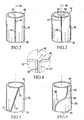
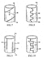
- a first aspect of which comprises a rotor body having a plurality of cylindrical bores each adapted to receive a piston for reciprocating movement therein, each of said bores being lined with a single ceramic liner characterised in that said ceramic liner comprises a single piece, said single piece having a first end, a second end, and a sidewall having a first split, said first split extending axially from said first end toward said second end.
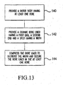
- An additional aspect of the invention comprises a method of forming a rotor having a ceramic bore liner that includes the steps of providing a rotor body having at least one bore and characterised by forming a split in an uncured ceramic cylinder, densifying the ceramic cylinder to provide a ceramic bore liner having a first end, a second end and a split having a width, and compressing the bore liner to decrease the width and securing the bore liner in the at least one bore.
Landscapes
- Engineering & Computer Science (AREA)
- General Engineering & Computer Science (AREA)
- Mechanical Engineering (AREA)
- Chemical & Material Sciences (AREA)
- Combustion & Propulsion (AREA)
- Pistons, Piston Rings, And Cylinders (AREA)
- Cylinder Crankcases Of Internal Combustion Engines (AREA)
Claims (5)
- Rotorkörper (22) mit mehreren zylindrischen Bohrungen (24), die jeweils zur Aufnahme eines Kolbens (30) ausgelegt sind, so dass dieser in ihnen hin- und hergeht, wobei jede Bohrung (30) mit einer einzigen keramischen Laufbuchse (42, 70, 80, 90, 100, 110, 120, 130) ausgekleidet ist, dadurch gekennzeichnet, dass die keramische Laufbuchse ein einziges Teil umfasst, das ein erstes Ende (48, 74, 94, 104, 112, 136), ein zweites Ende (50, 76, 86, 96, 106, 114, 138) und eine Seitenwand mit einem Spalt (44, 44', 72, 82, 92, 102, 116, 122, 132) hat, wobei sich der Spalt (44, 44', 72, 92, 102, 116, 122, 132) axial vom ersten Ende (48, 74, 84, 94, 104, 112, 136) zu dem zweite Ende (50, 76, 86, 96, 106, 114, 138) erstreckt.
- Rotorkörper nach Anspruch 1, wobei der Spalt (44, 44', 72, 82, 92, 102, 116, 122, 132) durch eine von einer zweiten Wand (54, 54') beabstandete erste Wand (52, 52') definiert ist.
- Rotorkörper nach Anspruch 1, wobei der Spalt (44, 44', 72, 82, 92, 102, 116, 122, 132) durch eine erste Wand (52, 52') definiert ist, die mit einer zweiten Wand (54, 54') in Kontakt steht.
- Rotorkörper nach Anspruch 1, der eine Hartlotschicht zwischen jeder der keramischen Laufbuchsen (42, 70, 80, 90, 100, 110, 120, 130) und jeder der Bohrungen (30) aufweist.
- Verfahren zum Bilden eines Rotors mit einer keramischen Laufbuchse, das die folgenden Schritte umfasst:Bereitstellen eines Rotorkörpers mit mindestens einer Bohrung (140), gekennzeichnet durch Bilden eines Spalts in einem ungehärteten keramischen Zylinder,Verdichten des keramischen Zylinders zur Bereitstellung einer keramischen Laufbuchse mit einem ersten Ende, einem zweiten Ende und einem Spalt mit einer Breite (142) undKomprimieren der Laufbuchse zur Reduzierung der Breite und Befestigen der Laufbuchse in der mindestens einen Bohrung (144).
Applications Claiming Priority (1)
| Application Number | Priority Date | Filing Date | Title |
|---|---|---|---|
| US11/192,268 US7469626B2 (en) | 2005-07-29 | 2005-07-29 | Split ceramic bore liner, rotor body having a split ceramic bore liner and method of lining a rotor bore with a split ceramic bore liner |
Publications (3)
| Publication Number | Publication Date |
|---|---|
| EP1748192A2 EP1748192A2 (de) | 2007-01-31 |
| EP1748192A3 EP1748192A3 (de) | 2008-03-26 |
| EP1748192B1 true EP1748192B1 (de) | 2014-08-27 |
Family
ID=36940379
Family Applications (1)
| Application Number | Title | Priority Date | Filing Date |
|---|---|---|---|
| EP06118055.0A Not-in-force EP1748192B1 (de) | 2005-07-29 | 2006-07-28 | Geteilte keramische Zylinderführung |
Country Status (2)
| Country | Link |
|---|---|
| US (1) | US7469626B2 (de) |
| EP (1) | EP1748192B1 (de) |
Families Citing this family (6)
| Publication number | Priority date | Publication date | Assignee | Title |
|---|---|---|---|---|
| EP2180967B1 (de) | 2007-07-24 | 2013-09-11 | Brinkmann Pumpen K.H. Brinkmann GmbH & Co. KG | Verfahren zur herstellung eines maschinengehäuses mit oberflächengehärteter fluidkammer |
| US7992652B2 (en) * | 2009-02-05 | 2011-08-09 | Atlas Copco Secoroc Llc | Fluid distributor cylinder for percussive drills |
| US10309380B2 (en) | 2011-11-16 | 2019-06-04 | Ocean Pacific Technologies | Rotary axial piston pump |
| US9322401B2 (en) * | 2014-02-10 | 2016-04-26 | General Electric Company | Linear compressor |
| US10094364B2 (en) | 2015-03-24 | 2018-10-09 | Ocean Pacific Technologies | Banded ceramic valve and/or port plate |
| US20250075794A1 (en) * | 2023-08-28 | 2025-03-06 | Hamilton Sundstrand Corporation | Piston rings and barrel sleeves |
Family Cites Families (26)
| Publication number | Priority date | Publication date | Assignee | Title |
|---|---|---|---|---|
| US813536A (en) * | 1904-03-28 | 1906-02-27 | Max Thier | Cylinder for internal-combustion motors and the like. |
| US2170015A (en) * | 1938-06-09 | 1939-08-22 | Ford Motor Co | Internal combustion engine |
| US2283424A (en) * | 1939-03-20 | 1942-05-19 | Thompson Prod Inc | Cylinder liner sleeve |
| US2635021A (en) * | 1941-07-03 | 1953-04-14 | Alward Kenneth Cutler | Cylinder liner |
| US3550233A (en) * | 1968-05-08 | 1970-12-29 | Lucas Industries Ltd | Methods of making rotors for piston type hydraulic pumps and motors |
| GB1235696A (en) | 1968-05-24 | 1971-06-16 | Laser Eng Dev Ltd | Reciprocating hydraulic pumps and motors of the axial type |
| US3709108A (en) * | 1970-11-27 | 1973-01-09 | Gen Signal Corp | Steel cylinder barrel having bonded bronze-iron liners |
| JPS5413852B2 (de) | 1972-01-17 | 1979-06-02 | ||
| JPS5675940A (en) * | 1979-11-21 | 1981-06-23 | Toshiba Corp | Cylinder for internal combustion engine |
| US4465040A (en) | 1980-12-05 | 1984-08-14 | Mack Trucks, Inc. | Valve guide insert |
| JPS58167848A (ja) | 1982-03-27 | 1983-10-04 | Toyota Motor Corp | 縦割型スリ−ブ |
| DE3437999A1 (de) | 1984-10-17 | 1986-04-17 | Sigri GmbH, 8901 Meitingen | Zylinder fuer arbeitsmaschine |
| NL8501315A (nl) * | 1985-05-08 | 1986-12-01 | Multinorm Bv | Pomp. |
| GB8703330D0 (en) * | 1987-02-13 | 1987-03-18 | Ae Plc | Ceramic cylinders |
| US5177037A (en) | 1991-05-21 | 1993-01-05 | Industrial Ceramic Technology, Inc. | High fracture toughness electro-discharge machineable ceramic whisker reinforced ceramic composites and tooling made therefrom |
| DE4301126C2 (de) | 1993-01-18 | 1995-05-24 | Danfoss As | Verfahren zum Montieren einer Laufbuchse in einem Grundkörper einer hydraulischen Maschine und hydraulische Maschine |
| US5581881A (en) * | 1994-10-17 | 1996-12-10 | Caterpillar Inc. | Method of making a cylinder barrel having ceramic bore liners |
| JPH0942150A (ja) | 1995-07-27 | 1997-02-10 | Toyota Autom Loom Works Ltd | 容量可変型斜板式圧縮機 |
| JPH09324694A (ja) * | 1996-06-06 | 1997-12-16 | Toyota Motor Corp | 多気筒シリンダブロック |
| US6254948B1 (en) | 1996-09-09 | 2001-07-03 | Phoenix Aktiengesellschaft | Slit protection for a tubular body |
| US5870990A (en) * | 1997-09-02 | 1999-02-16 | Ford Global Technologies, Inc. | Cylinder bore liner for an internal combustion engine |
| SE514243C2 (sv) | 1998-06-09 | 2001-01-29 | Flow Holdings Gmbh Sagl Llc | Förfarande för att åstadkomma en högtryckspress samt högtryckspress |
| FR2779489B1 (fr) | 1998-06-09 | 2001-04-06 | Valeo | Dispositif de commande hydraulique de freinage ou d'un embrayage, notamment pour vehicule automobile |
| DE10051420B4 (de) | 2000-10-17 | 2009-03-05 | Valeo Compressor Europe Gmbh | Zylinderblock eines Axialkolbenverdichters mit verlängerter Zylinderlauffläche |
| DE10223844B4 (de) * | 2002-05-28 | 2013-04-04 | Danfoss A/S | Wasserhydraulische Maschine |
| US6802244B1 (en) | 2003-04-25 | 2004-10-12 | Sauer-Danfoss, Inc. | Hydrostatic cylinder block and method of making the same |
-
2005
- 2005-07-29 US US11/192,268 patent/US7469626B2/en not_active Expired - Fee Related
-
2006
- 2006-07-28 EP EP06118055.0A patent/EP1748192B1/de not_active Not-in-force
Also Published As
| Publication number | Publication date |
|---|---|
| US7469626B2 (en) | 2008-12-30 |
| US20070039157A1 (en) | 2007-02-22 |
| EP1748192A2 (de) | 2007-01-31 |
| EP1748192A3 (de) | 2008-03-26 |
Similar Documents
| Publication | Publication Date | Title |
|---|---|---|
| US10774828B1 (en) | Composite valve seat system and method | |
| US11384756B1 (en) | Composite valve seat system and method | |
| EP0731301B1 (de) | Dichtungsvorrichtung | |
| US5704272A (en) | Axial piston energy converting device | |
| EP2678588B1 (de) | Axialkolbenpumpe mit kolben mit metallischen dichtungsringen | |
| EP1748192B1 (de) | Geteilte keramische Zylinderführung | |
| US6363897B2 (en) | Device for changing the control timing of the gas exchange valves of an internal combustion engine, in particular a hydraulic camshaft adjustment device of the rotary piston type | |
| CN112814893B (zh) | 液压活塞机 | |
| CN101653832A (zh) | 制造活塞式内燃机的缸套的缸壁上的工作面的加工方法 | |
| EP3191743B1 (de) | Kolbenanordnung | |
| US20230294050A1 (en) | High Pressure Homogenizer | |
| EP3555476B1 (de) | Pumpendichtung | |
| US11808360B2 (en) | Oil scraper ring for a piston rod | |
| US10094364B2 (en) | Banded ceramic valve and/or port plate | |
| CN100351515C (zh) | 旋转排量机器 | |
| JP2003343424A (ja) | 斜板式流体ポンプ・モータ | |
| CN211573723U (zh) | 高寿命的活塞环密封系统 | |
| JP7211747B2 (ja) | 斜軸式液圧回転機 | |
| EP4517087A1 (de) | Kolbenringe und zylinderlaufbuchsen | |
| US12492687B2 (en) | Insert and method for manufacturing fluid pump | |
| EP3800356B1 (de) | Beschichtung für verdichterauslassgehäuse | |
| EP3495657B1 (de) | Hydraulische rotationsmaschine vom axialkolbentyp | |
| JPS61215483A (ja) | ロ−タリ圧縮機 | |
| EP2898237A1 (de) | Kolbenring, kolben mit einem solchen ring und kolbenmaschine mit mindestens einem solchen kolben | |
| TW202225558A (zh) | 滑片泵 |
Legal Events
| Date | Code | Title | Description |
|---|---|---|---|
| PUAI | Public reference made under article 153(3) epc to a published international application that has entered the european phase |
Free format text: ORIGINAL CODE: 0009012 |
|
| AK | Designated contracting states |
Kind code of ref document: A2 Designated state(s): AT BE BG CH CY CZ DE DK EE ES FI FR GB GR HU IE IS IT LI LT LU LV MC NL PL PT RO SE SI SK TR |
|
| AX | Request for extension of the european patent |
Extension state: AL BA HR MK YU |
|
| PUAL | Search report despatched |
Free format text: ORIGINAL CODE: 0009013 |
|
| AK | Designated contracting states |
Kind code of ref document: A3 Designated state(s): AT BE BG CH CY CZ DE DK EE ES FI FR GB GR HU IE IS IT LI LT LU LV MC NL PL PT RO SE SI SK TR |
|
| AX | Request for extension of the european patent |
Extension state: AL BA HR MK YU |
|
| RIC1 | Information provided on ipc code assigned before grant |
Ipc: F04B 53/16 20060101AFI20060912BHEP Ipc: F04B 1/20 20060101ALI20080215BHEP Ipc: F16J 10/04 20060101ALI20080215BHEP |
|
| 17P | Request for examination filed |
Effective date: 20080916 |
|
| AKX | Designation fees paid |
Designated state(s): DE FR GB |
|
| 17Q | First examination report despatched |
Effective date: 20081121 |
|
| GRAP | Despatch of communication of intention to grant a patent |
Free format text: ORIGINAL CODE: EPIDOSNIGR1 |
|
| INTG | Intention to grant announced |
Effective date: 20140429 |
|
| GRAS | Grant fee paid |
Free format text: ORIGINAL CODE: EPIDOSNIGR3 |
|
| GRAA | (expected) grant |
Free format text: ORIGINAL CODE: 0009210 |
|
| AK | Designated contracting states |
Kind code of ref document: B1 Designated state(s): DE FR GB |
|
| REG | Reference to a national code |
Ref country code: GB Ref legal event code: FG4D |
|
| REG | Reference to a national code |
Ref country code: DE Ref legal event code: R096 Ref document number: 602006042828 Country of ref document: DE Effective date: 20141009 |
|
| REG | Reference to a national code |
Ref country code: DE Ref legal event code: R097 Ref document number: 602006042828 Country of ref document: DE |
|
| REG | Reference to a national code |
Ref country code: FR Ref legal event code: PLFP Year of fee payment: 10 |
|
| PLBE | No opposition filed within time limit |
Free format text: ORIGINAL CODE: 0009261 |
|
| STAA | Information on the status of an ep patent application or granted ep patent |
Free format text: STATUS: NO OPPOSITION FILED WITHIN TIME LIMIT |
|
| PGFP | Annual fee paid to national office [announced via postgrant information from national office to epo] |
Ref country code: GB Payment date: 20150624 Year of fee payment: 10 |
|
| 26N | No opposition filed |
Effective date: 20150528 |
|
| PGFP | Annual fee paid to national office [announced via postgrant information from national office to epo] |
Ref country code: FR Payment date: 20150624 Year of fee payment: 10 |
|
| PGFP | Annual fee paid to national office [announced via postgrant information from national office to epo] |
Ref country code: DE Payment date: 20150731 Year of fee payment: 10 |
|
| REG | Reference to a national code |
Ref country code: DE Ref legal event code: R119 Ref document number: 602006042828 Country of ref document: DE |
|
| GBPC | Gb: european patent ceased through non-payment of renewal fee |
Effective date: 20160728 |
|
| PG25 | Lapsed in a contracting state [announced via postgrant information from national office to epo] |
Ref country code: DE Free format text: LAPSE BECAUSE OF NON-PAYMENT OF DUE FEES Effective date: 20170201 Ref country code: FR Free format text: LAPSE BECAUSE OF NON-PAYMENT OF DUE FEES Effective date: 20160801 |
|
| REG | Reference to a national code |
Ref country code: FR Ref legal event code: ST Effective date: 20170331 |
|
| PG25 | Lapsed in a contracting state [announced via postgrant information from national office to epo] |
Ref country code: GB Free format text: LAPSE BECAUSE OF NON-PAYMENT OF DUE FEES Effective date: 20160728 |
|
| P01 | Opt-out of the competence of the unified patent court (upc) registered |
Effective date: 20230525 |