EP1748198A2 - Attache creuse auto-perforant - Google Patents
Attache creuse auto-perforant Download PDFInfo
- Publication number
- EP1748198A2 EP1748198A2 EP06253904A EP06253904A EP1748198A2 EP 1748198 A2 EP1748198 A2 EP 1748198A2 EP 06253904 A EP06253904 A EP 06253904A EP 06253904 A EP06253904 A EP 06253904A EP 1748198 A2 EP1748198 A2 EP 1748198A2
- Authority
- EP
- European Patent Office
- Prior art keywords
- fastener
- structural members
- cutting
- distal end
- construction
- Prior art date
- Legal status (The legal status is an assumption and is not a legal conclusion. Google has not performed a legal analysis and makes no representation as to the accuracy of the status listed.)
- Withdrawn
Links
- 238000005553 drilling Methods 0.000 title abstract description 16
- 238000010276 construction Methods 0.000 claims abstract description 25
- 238000005520 cutting process Methods 0.000 claims description 32
- 230000036346 tooth eruption Effects 0.000 claims description 21
- 239000000463 material Substances 0.000 claims description 13
- 229910000831 Steel Inorganic materials 0.000 claims description 11
- 239000010959 steel Substances 0.000 claims description 11
- 239000002023 wood Substances 0.000 claims description 9
- 238000000034 method Methods 0.000 claims description 5
- 230000000149 penetrating effect Effects 0.000 claims 1
- 239000011295 pitch Substances 0.000 description 8
- 230000001133 acceleration Effects 0.000 description 7
- 238000005266 casting Methods 0.000 description 3
- 206010041662 Splinter Diseases 0.000 description 2
- 238000012986 modification Methods 0.000 description 2
- 230000004048 modification Effects 0.000 description 2
- 229910000906 Bronze Inorganic materials 0.000 description 1
- 229920002522 Wood fibre Polymers 0.000 description 1
- HCHKCACWOHOZIP-UHFFFAOYSA-N Zinc Chemical compound [Zn] HCHKCACWOHOZIP-UHFFFAOYSA-N 0.000 description 1
- 230000009471 action Effects 0.000 description 1
- 229910052782 aluminium Inorganic materials 0.000 description 1
- XAGFODPZIPBFFR-UHFFFAOYSA-N aluminium Chemical compound [Al] XAGFODPZIPBFFR-UHFFFAOYSA-N 0.000 description 1
- 239000010974 bronze Substances 0.000 description 1
- 230000008859 change Effects 0.000 description 1
- 239000002131 composite material Substances 0.000 description 1
- KUNSUQLRTQLHQQ-UHFFFAOYSA-N copper tin Chemical compound [Cu].[Sn] KUNSUQLRTQLHQQ-UHFFFAOYSA-N 0.000 description 1
- 230000001351 cycling effect Effects 0.000 description 1
- 238000013461 design Methods 0.000 description 1
- SOCTUWSJJQCPFX-UHFFFAOYSA-N dichromate(2-) Chemical compound [O-][Cr](=O)(=O)O[Cr]([O-])(=O)=O SOCTUWSJJQCPFX-UHFFFAOYSA-N 0.000 description 1
- 238000009826 distribution Methods 0.000 description 1
- 238000003780 insertion Methods 0.000 description 1
- 230000037431 insertion Effects 0.000 description 1
- 238000007689 inspection Methods 0.000 description 1
- 238000005304 joining Methods 0.000 description 1
- 229910052751 metal Inorganic materials 0.000 description 1
- 239000002184 metal Substances 0.000 description 1
- 150000002739 metals Chemical class 0.000 description 1
- 239000004033 plastic Substances 0.000 description 1
- 229920003023 plastic Polymers 0.000 description 1
- 239000007787 solid Substances 0.000 description 1
- 238000006467 substitution reaction Methods 0.000 description 1
- 230000007704 transition Effects 0.000 description 1
- 239000002025 wood fiber Substances 0.000 description 1
- 229910052725 zinc Inorganic materials 0.000 description 1
- 239000011701 zinc Substances 0.000 description 1
Images


Classifications
-
- F—MECHANICAL ENGINEERING; LIGHTING; HEATING; WEAPONS; BLASTING
- F16—ENGINEERING ELEMENTS AND UNITS; GENERAL MEASURES FOR PRODUCING AND MAINTAINING EFFECTIVE FUNCTIONING OF MACHINES OR INSTALLATIONS; THERMAL INSULATION IN GENERAL
- F16B—DEVICES FOR FASTENING OR SECURING CONSTRUCTIONAL ELEMENTS OR MACHINE PARTS TOGETHER, e.g. NAILS, BOLTS, CIRCLIPS, CLAMPS, CLIPS OR WEDGES; JOINTS OR JOINTING
- F16B25/00—Screws that cut thread in the body into which they are screwed, e.g. wood screws
- F16B25/0036—Screws that cut thread in the body into which they are screwed, e.g. wood screws characterised by geometric details of the screw
- F16B25/0084—Screws that cut thread in the body into which they are screwed, e.g. wood screws characterised by geometric details of the screw characterised by geometric details of the tip
-
- F—MECHANICAL ENGINEERING; LIGHTING; HEATING; WEAPONS; BLASTING
- F16—ENGINEERING ELEMENTS AND UNITS; GENERAL MEASURES FOR PRODUCING AND MAINTAINING EFFECTIVE FUNCTIONING OF MACHINES OR INSTALLATIONS; THERMAL INSULATION IN GENERAL
- F16B—DEVICES FOR FASTENING OR SECURING CONSTRUCTIONAL ELEMENTS OR MACHINE PARTS TOGETHER, e.g. NAILS, BOLTS, CIRCLIPS, CLAMPS, CLIPS OR WEDGES; JOINTS OR JOINTING
- F16B25/00—Screws that cut thread in the body into which they are screwed, e.g. wood screws
- F16B25/001—Screws that cut thread in the body into which they are screwed, e.g. wood screws characterised by the material of the body into which the screw is screwed
- F16B25/0031—Screws that cut thread in the body into which they are screwed, e.g. wood screws characterised by the material of the body into which the screw is screwed the screw being designed to be screwed into different materials, e.g. a layered structure or through metallic and wooden parts
-
- F—MECHANICAL ENGINEERING; LIGHTING; HEATING; WEAPONS; BLASTING
- F16—ENGINEERING ELEMENTS AND UNITS; GENERAL MEASURES FOR PRODUCING AND MAINTAINING EFFECTIVE FUNCTIONING OF MACHINES OR INSTALLATIONS; THERMAL INSULATION IN GENERAL
- F16B—DEVICES FOR FASTENING OR SECURING CONSTRUCTIONAL ELEMENTS OR MACHINE PARTS TOGETHER, e.g. NAILS, BOLTS, CIRCLIPS, CLAMPS, CLIPS OR WEDGES; JOINTS OR JOINTING
- F16B25/00—Screws that cut thread in the body into which they are screwed, e.g. wood screws
- F16B25/10—Screws performing an additional function to thread-forming, e.g. drill screws or self-piercing screws
- F16B25/103—Screws performing an additional function to thread-forming, e.g. drill screws or self-piercing screws by means of a drilling screw-point, i.e. with a cutting and material removing action
Definitions
- the present invention relates to fasteners, and in particular to fasteners having load capacities similar to bolts but which require no pre-drilling.
- a bolted connection typically includes a threaded bolt fit within a pre-drilled bore hole formed through the members to be connected, and a threaded nut tightened on the protruding end of the bolt to fasten the structural members together.
- high load bolted connections will comprise several bolts at the interface between adjoined structural members.
- the predrilled bore hole diameter is preferably provided 0.79 mm to, at most, 1.59 mm (1/32 nd to, at most, 1/16 th inch) larger than the nominal bolt diameter.
- the predrilled bore holes are made larger than this range to facilitate ease of construction. This relatively larger bore hole diameter often goes unnoticed during inspection due to the bolt head and nut entirely covering the predrilled bore hole.
- a difference in diameter between the bore hole and bolt allows for acceleration of the bolt within the bore hole under shear loads. This acceleration transfers greater stresses to the adjoining structural members. This acceleration also creates impact forces in the bore holes, thereby increasing the chance that the structural members will split or fracture at the bolted connection. Such impact forces within bolted connections can be particularly devastating when the shear loads are cycling loads as they are in earthquakes and hurricanes. In such situations, each reversal of the shear loading tends to widen the bore hole resulting in even greater accelerations and eventual failure of the bolted connection. It is noteworthy that even properly sized bore holes allow for some play between the bore hole and bolt, thus allowing the disadvantageous acceleration and impact loads described above.
- a further disadvantage to conventional bolted connections is that, in bolted connections comprising a plurality of bolts, non-uniform clearances within the various bolts and bore holes can result in non-uniform loading of the various bolts. Thus, some bolts wind up bearing more of the load than others and are subject to fatigue and failure at a greater rate than other bolts in the structural connection.
- a fastener for fastening together two or more structural members in a construction.
- the fastener includes helical threads formed along a portion of an outer surface of the fastener for pulling the distal end of the fastener into at least one of the structural members.
- the fastener further includes a cutting surface provided in an annular configuration at the distal end of the fastener for cutting into the at least one structural member as the helical threads pull the distal end into the at least one structural member.
- a cylindrical bore is further formed in the distal end of the fastener and through at least a portion of the fastener, the bore capable of receiving a plug from the structural member. The plug is cut by the cutting surface as the fastener is pulled into the at least one structural member.
- the cutting surface may be formed by a plurality of cutting teeth.
- the teeth and helical threads are formed in such a way that the helical threads pull the fastener in at a rate at which the cutting teeth may smoothly cut into one or both structural members.
- the plug formed from the structural member and received within the cylindrical bore adds to the strength and performance of the fastener under shear loads.
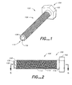
- Figs. 1-10C which in general relate to a self-drilling fastener capable of supporting high loads.
- fastener is used to describe any of a variety of elongate elements such as for example bolts, screws, lag screws and/or anchors having features of the present invention for fastening members together as described hereinafter. It is understood that the present invention may be embodied in many different forms and should not be construed as being limited to the embodiments set forth herein. Rather these embodiments are provided so that this disclosure will be thorough and complete and will fully convey the invention to those skilled in the art.
- a self-drilling fastener 100 including a head 102 at a proximal end 104 of the fastener, a shank 106 extending from the head 102, and cutting teeth 108 at a distal end 110 of the fastener opposite the proximal end 104.
- the shank 106 includes a threaded portion 112 having helical threads 114, and the shank 106 includes an unthreaded shank portion 116 between the head 102 and the threaded portion 112.
- fastener 100 further includes a cylindrical bore 118 formed through the distal end 110 and extending at least part way through the shank 106 toward the proximal end 104 of fastener 100.
- the head 102 may have a diameter of about 38.1 mm (1.5 inches) and may be about 12.7 mm (0.5 inches) in thickness. These dimensions may vary in alternative embodiments.
- the head 102 may be hexagonal in shape, though other known shapes are contemplated.
- the overall length of the fastener from proximal end 104 to distal end 110 may be about 127 mm (5 inches).
- the unthreaded shank portion 116 may be about 6.4 mm (about 0.25 inches) and the threaded portion 112 may be about 101.6 mm (about 4 inches).
- the diameter of the unthreaded shank portion 116 and the outer diameter of the threaded portion 112 may be about 22.2 mm (7/8 inches). It is understood that these dimensions are by way of example only, and each of these dimensions may vary in alternative embodiments.
- the fastener 100 may be manufactured from 1022 steel (SAE Grade 5) with a finish coat of zinc and dichromate. Other materials are contemplated, including for example other metals such as bronze and aluminum castings, and hard plastics/composites.
- Figs. 10A-10C illustrate an example of how fastener 100 may operate to fasten together two structural members 120 and 122.
- the structural member 120 may be a steel structural member which is to be affixed to a wooden structural member 122.
- the steel structural member may be a connector, holdown or other steel plate.
- the fastener 100 may be used to connect a wide variety of other structural members.
- the structural members that may be affixed by fastener 100 may alternatively both be wood, the members may be wood and masonry, or the members may be steel and masonry.
- Other structural members may be connected using the fastener 100 according to the present invention, including for example concrete with any of the above structural members.
- Figs. 10A-10C show a relatively thin member 120 being fastened to a relatively thick member 122, it is understood that the fastener 100 may operate to fasten members of varying relative thicknesses in alternative embodiments.
- two structural members are shown being fastened by fastener 100, it is understood that greater than two structural members may be affixed together by a single fastener 100 in alternative embodiments.
- the distal end 110 of the fastener 100 is positioned at a point of entry into the structural member 120.
- the fastener may self-drill through both members 120, 122 to affix those members together.
- the structural member 120 is a steel plate
- the first member 120 may have a preformed hole for receiving the fastener. In this instance, the fastener 100 is placed through the preformed hole in structural member 120 and against a point of entry in the second structural member 122.
- member 120 is for example wood, it is understood that a countersink (not shown) may be provided in the member 120 at the point of entry of the fastener so that the proximal end of fastener is flush with the outer surface of member 120 upon full insertion of the fastener into the members 120, 122.
- the cutting teeth 108 make an annular cut into member(s) 120 and/or 122 so that a cylindrical portion of the structural member(s), referred to herein as plug 124, is left intact in the structural member(s), which plug fills cylindrical bore 118 of fastener 100 as the fastener is driven into the members 120, 122.
- the provision of the plug 124 with cylindrical bore 118 increases the strength and performance of the fastener 100 under shear loads.
- the plug 124 may be a single cylindrical piece, or it may chip, splinter, break or otherwise be formed of more than one unitary piece, and still improve the strength and performance of the fastener 100 under shear loads.
- the configuration of the cutting teeth 108 is related to the helical threads in that the teeth configuration and thread pitch are provided to allow the teeth to cut smoothly into the members as the fastener is pulled into the members by the helical threads.
- the thread pitch i.e ., the number of helical threads per inch along the shank
- large compressive forces may be generated at the distal end of the fastener as it is pulled into the members. These forces may make it difficult to drive the fastener into the members, and, if sufficiently large, may result in "blow out,” where the structural member splits near the distal surface of one or both structural members.
- the fastener may be an about 22.2 mm (7/8 inch) fastener having an outer diameter of the shank 106 of about 22.2 mm (7/8 inches).
- the pitch of helical threads 114 may be between about 0.31 and 0.59 threads per mm (between 8 and 15 threads per inch), or more specifically between about 0.31 and 0.47 threads per mm (8 and 12 threads per inch), or more specifically about 0.39 threads per mm (10 threads per inch). It is understood that the outer diameter of shank 106 may be larger or smaller than about 22.2 mm (7/8 inches), and that the pitch may vary outside of about 0.31 and 0.59 threads per mm (8 to 15 threads per inch).
- the diameter of the shank may range between about 9.5 mm (3/8 inches) and about 25.4 mm (1 inch).
- the thread pitch may vary proportionately, disproportionately or not at all relative to the diameter.
- each helical thread 114 may have a relatively flat upper surface, as opposed to coming to a "v" shaped edge as is commonly found.
- the flat threads facilitate crushing of the wood fibers or material of the structural member during the self-drilling by the fastener. This reduces the likelihood of cracks developing in the structural member at the drilled hole better than a "v" shaped edge which tends to cut the material.
- the spaces between the threads may also be flat instead of forming a "v” shaped valley.
- the upper surfaces of the threads and/or the spaces between the threads may be "v" shaped in alternative embodiments.
- the depth, d, of the helical threads may be between about 1.27 mm (0.05 inches) and about 2.54 mm (0.1 inches) and more specifically about 1.78 mm (0.07 inches). It is understood that the depth of the threads may be outside of the range set forth above in alternative embodiments.
- the size and configuration of the teeth 108, in conjunction with the threads 114, are selected to allow a smooth cutting action of the teeth into the structural member as the fastener is pulled in.
- the plug 124 may chip, splinter or otherwise break into multiple pieces while still adding to the structural stiffness of the fastener 100.
- annular ring For an about 22.2 mm (7/8 inch) fastener, there may be 6 cutting teeth 108 formed in an annular ring at the distal end of the fastener 100, though there may be more or less than that in alternative embodiments.
- the outer diameter of the annular ring may be slightly more than or equal to the inner diameter of the helical thread portion 112 (i.e., the diameter at the spaces between helical threads 114).
- each tooth 108 is formed of a vertical cutting edge 130 and a back side 132 having a straight, sloped surface leading to the cutting edge of the next tooth behind it.
- each vertical cutting edge may have a height of about 4.19 mm to 4.32 mm (about 0.165 to 0.17 inches), and more specifically about 4.27 mm (about 0.168 inches). The height may vary outside of this range in alternative embodiments.
- the teeth may alternate between leaning slightly inward and leaning slightly outward.
- a first tooth 108a may angle slightly inward toward the axial center of the fastener, while a next adjacent tooth 108b may angle slightly outward away from the axial center of the fastener.
- the degree of inward and outward lean may be about 5° to 6° toward/away from the axial center of the fastener, and more specifically about 5.3° toward/away from the axial center of the fastener.
- the teeth may have no inward or outward lean in alternative embodiments. It is understood that other teeth configurations are possible.
- the fastener may include a tooth design that has a small radius joining the vertical face of one tooth with the sloping back of the adjacent tooth as is typically done on saw blades and hole drilling wood bits, in lieu of the sharp transition between tooth face and adjacent angled back.
- teeth 108 may be provided in other configurations, some with very sharp cutting teeth. As indicated above, in embodiments of the invention, there may be a relation between the cutting teeth and pitch of the threads 114. For example, if particularly sharp cutting teeth are provided which are adept at cutting quickly through the structural material, this may allow for coarser threads which pull the fastener more quickly. Those of skill in the art would understand that configuring the teeth 108 in configurations other than those set forth above may allow for appropriate thread pitches above and/or below the ranges set forth above. It is also contemplated that even though fastener 100 is provided with teeth that are especially adept at cutting through the structural members, a high pitch count for threads 114 may still be provided.
- the cylindrical bore 118 may be formed by drilling through the distal end 110 of the fastener through at least a portion of the shank 106.
- the fastener could alternatively be formed by casting where the bore 118 is formed during the casting process. Referring to Fig. 5 for example, in embodiments of the invention, the cylindrical bore may extend to about 12.7 mm (about 1 ⁇ 2 inch) of the underside 102a of the head 102.
- the cylindrical bore may extend to greater than about 12.7 mm (1 ⁇ 2 inch) of the underside of the head, may extend to less than about 12.7 mm (1 ⁇ 2 inch) of the underside of the head, and may extend past the underside of the head (i.e., between the underside of the head and the proximal end 104 of the head).
- the cylindrical bore may be drilled with a diameter of approximately about 12.7 mm (approximately 0.5 inches). It is understood that the cylindrical bore and the thickness of cylindrical wall of the shank 106 may vary in alternative embodiments.
- the bottom of the cylindrical bore (i.e., the portion nearest the proximal end of the fastener) may be radiused or non-radiused; that is, the end of the drill bit forming the bore may be shaped such that there is a gradual slope between the cylindrical sides of the bore 118 and the bottom of the bore, or there may be an abrupt change from the cylindrical sides of the bore to the bottom of the bore.
- the cutting teeth 108, threads 114 and cylindrical bore 118 allow the fastener 100 according to the present invention to be self-drilling without lead holes despite the relatively large diameter of the fastener.
- a countersink or partial lead hole may be provided so that the fastener is inserted part way and self-drills the remainder of its length.
- the self-drilling fastener 100 according to the present invention bores its own hole in the structural members and there is no play between the fastener and the hole it forms.
- the initial stiffness of the connection using the present invention is higher than in predrilled conventional bolt connections, and the problems of acceleration and impact forces found with conventional bolt connections is alleviated.
- each of the fasteners in the connection begins resisting an applied load simultaneously, instead of at different times as found in conventional bolt connections.
- the fastener 100 may be used to affix a steel plate to wood.
- the fastener may be inserted through a preformed hole in the steel and driven into the solid wood as described above to affix the members together.
- the preformed hole may be the same diameter as the outer diameter of threads 114 and unthreaded shank portion 116.
- the preformed hole in the steel plate may have a diameter larger than the diameter of the shank portion 116 in alternative embodiments.
Landscapes
- Engineering & Computer Science (AREA)
- General Engineering & Computer Science (AREA)
- Mechanical Engineering (AREA)
- Physics & Mathematics (AREA)
- Geometry (AREA)
- Joining Of Building Structures In Genera (AREA)
Applications Claiming Priority (1)
| Application Number | Priority Date | Filing Date | Title |
|---|---|---|---|
| US11/191,187 US20070025827A1 (en) | 2005-07-27 | 2005-07-27 | Hollow self-drilling fastener |
Publications (1)
| Publication Number | Publication Date |
|---|---|
| EP1748198A2 true EP1748198A2 (fr) | 2007-01-31 |
Family
ID=37211460
Family Applications (1)
| Application Number | Title | Priority Date | Filing Date |
|---|---|---|---|
| EP06253904A Withdrawn EP1748198A2 (fr) | 2005-07-27 | 2006-07-26 | Attache creuse auto-perforant |
Country Status (5)
| Country | Link |
|---|---|
| US (1) | US20070025827A1 (fr) |
| EP (1) | EP1748198A2 (fr) |
| JP (1) | JP2007032841A (fr) |
| AU (1) | AU2006202897A1 (fr) |
| CA (1) | CA2551538A1 (fr) |
Cited By (1)
| Publication number | Priority date | Publication date | Assignee | Title |
|---|---|---|---|---|
| ITBS20110072A1 (it) * | 2011-05-19 | 2012-11-20 | Si Al S R L | Sistema di ancoraggio per un elemento anticaduta e relativo metodo di installazione |
Families Citing this family (6)
| Publication number | Priority date | Publication date | Assignee | Title |
|---|---|---|---|---|
| DE102007038976A1 (de) * | 2007-08-17 | 2009-03-12 | Ludwig Hettich & Co. | Schraubanker für Befestigungen in Beton und Mauerwerk |
| US9763720B2 (en) | 2009-11-17 | 2017-09-19 | Wright Medical Technology, Inc. | Method and device for insertion of orthopedic fixation pin with blind hole |
| ES2439870T3 (es) * | 2009-12-03 | 2014-01-27 | Biedermann Technologies Gmbh & Co. Kg | Tornillo óseo |
| EP2361574B1 (fr) | 2010-02-26 | 2014-01-08 | Biedermann Technologies GmbH & Co. KG | Vis à os |
| EP3612117B1 (fr) | 2017-04-21 | 2023-09-20 | DePuy Synthes Products, Inc. | Cannelures inclinées dans des vis osseuses canulées |
| US10697490B2 (en) * | 2018-07-24 | 2020-06-30 | Ojjo, Inc. | Threaded truss foundations and related systems, methods, and machines |
Family Cites Families (28)
| Publication number | Priority date | Publication date | Assignee | Title |
|---|---|---|---|---|
| US126366A (en) * | 1872-04-30 | Improvement in wood-screws | ||
| US575792A (en) * | 1897-01-26 | Animal-trap | ||
| US1294268A (en) * | 1915-08-26 | 1919-02-11 | Edward C Holmes | Screw-spike. |
| US1330792A (en) * | 1919-04-22 | 1920-02-17 | Henry H Frick | Set-screw |
| US2062257A (en) * | 1934-12-18 | 1936-11-24 | Harry Barker | Tubular saw |
| DE1255395B (de) * | 1965-07-19 | 1967-11-30 | Dibotec A G | Selbstbohrduebel |
| US3949641A (en) * | 1974-11-04 | 1976-04-13 | The Steel Company Of Canada, Limited | Self-drilling screw |
| DE3471982D1 (en) * | 1983-09-02 | 1988-07-14 | Boesner Friedrich Gmbh | Connecting element for two machinery castings or structural members, like fitted antifatigue threaded bolts |
| US4601625A (en) * | 1984-05-11 | 1986-07-22 | Illinois Tool Works Inc. | Self drilling threaded insert for drywall |
| US4973209A (en) * | 1985-03-28 | 1990-11-27 | Conti Fasteners Ag | Screw for contaminated pre-tapped holes |
| US4764068A (en) * | 1987-03-06 | 1988-08-16 | Sps Technologies, Inc. | Knurled cup-point set screw |
| US5234299A (en) * | 1987-08-03 | 1993-08-10 | Giannuzzi Louis | Self-drilling anchor |
| US5073074A (en) * | 1990-07-26 | 1991-12-17 | Sps Technologies, Inc. | Set screw |
| US5160225A (en) * | 1991-08-23 | 1992-11-03 | Chern T P | Structure of a self-drilling threaded insert for use on drywall |
| US5833415A (en) * | 1992-09-22 | 1998-11-10 | Titan Technology, Inc. | Anchor insert improvement |
| US5308203A (en) * | 1992-09-22 | 1994-05-03 | Titan Technologies, Inc. | Saw tipped anchor insert |
| US5536121A (en) * | 1992-09-22 | 1996-07-16 | Titan Technologies, Inc. | Anchor insert |
| US6030162A (en) * | 1998-12-18 | 2000-02-29 | Acumed, Inc. | Axial tension screw |
| US5630688A (en) * | 1995-02-28 | 1997-05-20 | Peerless Lighting Corporation | Self-tapping sleeve |
| US5803678A (en) * | 1995-06-20 | 1998-09-08 | American Saw & Mfg. Company | Hole cutting tools |
| US5692864A (en) * | 1995-12-21 | 1997-12-02 | K & R Industries, Inc. | Self-threading anchor with spreadable leg portions joined by a frangible drill end portion |
| US5782442A (en) * | 1997-01-22 | 1998-07-21 | Black Diamond Equipment, Ltd. | Ice screw with foldable crank handle |
| FR2806637B1 (fr) * | 2000-03-23 | 2002-07-12 | Zedel | Dispositif d'amarrage amovible equipe d'une degaine |
| US6635039B1 (en) * | 2000-07-19 | 2003-10-21 | Tyco Healthcare Retail Services Ag | Package for carrying plural pantiliners |
| DE10064714A1 (de) * | 2000-12-22 | 2002-07-04 | Hilti Ag | Selbstfurchende Schraube |
| US6588992B2 (en) * | 2001-02-06 | 2003-07-08 | Black & Decker Inc. | Hole saw |
| CA2390912C (fr) * | 2001-07-05 | 2008-01-29 | Depuy France | Vis autotaraudeuse pour chirurgie de petits os |
| US6505799B1 (en) * | 2002-01-04 | 2003-01-14 | Black Diamond Equipment, Ltd. Inc. | Ice screw with non-linear taper |
-
2005
- 2005-07-27 US US11/191,187 patent/US20070025827A1/en not_active Abandoned
-
2006
- 2006-07-04 CA CA002551538A patent/CA2551538A1/fr not_active Abandoned
- 2006-07-06 AU AU2006202897A patent/AU2006202897A1/en not_active Abandoned
- 2006-07-26 JP JP2006203082A patent/JP2007032841A/ja active Pending
- 2006-07-26 EP EP06253904A patent/EP1748198A2/fr not_active Withdrawn
Cited By (1)
| Publication number | Priority date | Publication date | Assignee | Title |
|---|---|---|---|---|
| ITBS20110072A1 (it) * | 2011-05-19 | 2012-11-20 | Si Al S R L | Sistema di ancoraggio per un elemento anticaduta e relativo metodo di installazione |
Also Published As
| Publication number | Publication date |
|---|---|
| AU2006202897A1 (en) | 2007-02-15 |
| JP2007032841A (ja) | 2007-02-08 |
| US20070025827A1 (en) | 2007-02-01 |
| CA2551538A1 (fr) | 2007-01-27 |
Similar Documents
| Publication | Publication Date | Title |
|---|---|---|
| US8192123B2 (en) | Drywall fastener | |
| JP5180281B2 (ja) | セルフドリルアンカー | |
| CN102132049B (zh) | 自钻孔固定器 | |
| US6050765A (en) | Fastener for logs and fastening technique therefor | |
| CA2216836C (fr) | Vis de metal pour fixation a une structure de bois en relation de cisaillement | |
| CA2723387C (fr) | Attache autoperceuse | |
| US7255523B2 (en) | Dual threaded screw for composite materials | |
| US8137042B2 (en) | Fastener for securing first and second components together and method of using same | |
| JP2007527487A (ja) | 自己穿設式アンカー | |
| US20100278614A1 (en) | Fixing device | |
| US8070405B2 (en) | Self drilling bolt with anchor | |
| EP1748198A2 (fr) | Attache creuse auto-perforant | |
| CN1138046C (zh) | 用于连接至少两个木结构件和一个接合板的连接元件 | |
| CA3062913C (fr) | Ancre de panneau mural | |
| US9016995B1 (en) | Self-countersinking fastener | |
| NZ524480A (en) | Screw for concrete and masonry with varying outside diameter over thread | |
| EP1485627B1 (fr) | Dispositif de fixation et procede de fixation a un substrat | |
| AU2005333514B8 (en) | Pin fastener for achieving metal-to-metal connections | |
| EP4686842A1 (fr) | Fixation auto-foreuse auto-taraudeuse | |
| JP4183434B2 (ja) | 建材用ビス | |
| US20260036156A1 (en) | Wallboard anchor | |
| CN100485201C (zh) | 自钻锚 | |
| CA2583072C (fr) | Ancrage autotaraudeur | |
| JPH0811964B2 (ja) | 木ねじ | |
| HK1072970B (en) | Fixing device and method for fixing to a substrate |
Legal Events
| Date | Code | Title | Description |
|---|---|---|---|
| PUAI | Public reference made under article 153(3) epc to a published international application that has entered the european phase |
Free format text: ORIGINAL CODE: 0009012 |
|
| AK | Designated contracting states |
Kind code of ref document: A2 Designated state(s): AT BE BG CH CY CZ DE DK EE ES FI FR GB GR HU IE IS IT LI LT LU LV MC NL PL PT RO SE SI SK TR |
|
| AX | Request for extension of the european patent |
Extension state: AL BA HR MK YU |
|
| STAA | Information on the status of an ep patent application or granted ep patent |
Free format text: STATUS: THE APPLICATION IS DEEMED TO BE WITHDRAWN |
|
| 18D | Application deemed to be withdrawn |
Effective date: 20090203 |