EP1748220A2 - Treibkette und Treibvorrichtung - Google Patents
Treibkette und Treibvorrichtung Download PDFInfo
- Publication number
- EP1748220A2 EP1748220A2 EP06015815A EP06015815A EP1748220A2 EP 1748220 A2 EP1748220 A2 EP 1748220A2 EP 06015815 A EP06015815 A EP 06015815A EP 06015815 A EP06015815 A EP 06015815A EP 1748220 A2 EP1748220 A2 EP 1748220A2
- Authority
- EP
- European Patent Office
- Prior art keywords
- pin
- pressed
- power transmission
- pulley
- link
- Prior art date
- Legal status (The legal status is an assumption and is not a legal conclusion. Google has not performed a legal analysis and makes no representation as to the accuracy of the status listed.)
- Granted
Links
Images

Classifications
-
- F—MECHANICAL ENGINEERING; LIGHTING; HEATING; WEAPONS; BLASTING
- F16—ENGINEERING ELEMENTS AND UNITS; GENERAL MEASURES FOR PRODUCING AND MAINTAINING EFFECTIVE FUNCTIONING OF MACHINES OR INSTALLATIONS; THERMAL INSULATION IN GENERAL
- F16G—BELTS, CABLES, OR ROPES, PREDOMINANTLY USED FOR DRIVING PURPOSES; CHAINS; FITTINGS PREDOMINANTLY USED THEREFOR
- F16G5/00—V-belts, i.e. belts of tapered cross-section
- F16G5/16—V-belts, i.e. belts of tapered cross-section consisting of several parts
- F16G5/18—V-belts, i.e. belts of tapered cross-section consisting of several parts in the form of links
Definitions
- the present invention relates to a power transmission chain, and more particularly, to a power transmission chain preferable for a continuously variable transmission (CVT) of an automobile or the like and a power transmission device using this power transmission chain.
- CVT continuously variable transmission
- a power transmission chain (1) there has been proposed one which includes: a plurality of links (31); a plurality of pins (34) and a plurality of interpieces (35) which are inserted through the links (31) and move in a rolling and contacting manner relatively; wherein the interpiece (35) is set to be shorter than the pin (34), end faces of the pin (34) which are inclined surfaces corresponding to the shapes of conical sheave faces (2c) and (2d) of a fixing sheave (2a) and a movable sheave (2b) of a pulley (2) contact the conical sheave faces (2c) and (2d) in a state where end faces of the interpiece (35) do not contact respective conical sheave faces (2c) and (2d), and power is transmitted by a frictional force caused by this contact (Publication of Japanese Patent Application Laid-open No. 2004-301257 ).
- the pin (34) is fixed to the link (31) by pressing; however, when pressing, as shown in Fig. 6, the upper edge (34a) of the front end of the pin (34) enters a through hole (32) of the link (31) previously and depending on the shape, the size, and the pressing condition or the like, a pressing margin is concentrated on a lower edge (34b) of the front end when the lower edge (34b) of the front end enters the through hole (32), and due to this concentration of stresses, this portion (31a) of the link (31) may be transformed or be trimmed.
- An object of the present invention is to provide a power transmission chain and a power transmission device which can relax concentration of stresses generated in a link when pressing and prevent the link from being trimmed and being transformed.
- a power transmission chain includes: a plurality of links having through holes through which pins are inserted; and a plurality of pins for connecting the links aligned in a chain width direction each other; and the end faces of the pin contacting sheave faces of a pulley and a power being transmitted by a frictional force caused by this contact; wherein upper and lower edges of the pin are pressed into upper and lower edges of the through hole so as to connect the pin with the link, and an end of the pin which is located at a front end side when the pin is pressed is formed in a shape so that the upper and lower edges of the pin are pressed at a same time.
- the pin is formed by a link holding part having an even sectional shape and the link pressed therein and a pulley abutting part formed at opposite ends of the link holding part and having inclined surfaces corresponding to the sheave faces of the pulley.
- the upper edge of the front end of the pin is pressed into the through hole of the link previously and then, the lower edge of the front end of the pin is pressed into the through hole of the link.
- the pin is formed in a shape so that the upper and lower edges of the pin are pressed at the same time.
- the end of the pin is formed in the shape which is appropriate for pressing.
- a power transmission chain includes: a plurality of links having through holes through which pins are inserted; and a plurality of pins for connecting the links aligned in a chain width direction each other; and the end faces of the pin contacting sheave faces of a pulley and a power being transmitted by a frictional force caused by this contact; wherein upper and lower edges of the pin are pressed into upper and lower edges of the through hole so as to connect the pin with the link, and the pin is formed by a link holding part having an even sectional shape and the link pressed therein and a pulley abutting part formed at opposite ends of the link holding part and having inclined surfaces corresponding to the sheave faces of the pulley, and an upper edge of the pulley abutting part located at a front end side when the pin is pressed is deleted.
- the pin is manufactured in such a manner that a rod or a liner material is provided with a drawing process so as to have a required sectional shape, then, the inclined end face is formed by a press work, and after being provided with a heat treatment, a polishing process is provided so as to make the upper edge at the front end into a no-pressed part.
- an inclined face having a pressing margin which gradually increases is provided at a border between the upper edge of the pulley abutting part located at the front end side when the pin is pressed and an upper edge of the link holding part, and an inclined face having a pressing margin which gradually increases is also provided at a border between a lower edge of the pulley abutting part located at a front end side when the pin is pressed and a lower edge of the link holding part.
- the power transmission chain includes a plurality of links having front and back insertion parts through which the pins are inserted; and a plurality of first pins and a plurality of second pins which are aligned back and forth to connect the links which are aligned in a chain width direction so that the front insertion part of one link corresponds to the back insertion part of another link; wherein the first pin and the second pin move in a rolling and contacting manner relatively so as to enable bending in a longitudinal direction of the links.
- This power transmission chain is manufactured, for example, by horizontally holding the necessary number of pins on a table, and then, pressing the links one by one or by several pieces collectively.
- a power transmission device includes: a first pulley having conical sheave faces; a second pulley having conical sheave faces; and a power transmission chain provided over the first and second pulleys; wherein the power transmission chain is according to any one of the above-described power transmission chains.
- This power transmission device becomes one preferable to be used as a continuously variable transmission of an automobile or the like.
- the durability of the link can be improved.
- a power transmission chain (1) may include a plurality of links (11) having front and back insertion parts (12) and (13) which are disposed at predetermined intervals in a chain longitudinal direction; and a plurality of pins (14) and a plurality of interpieces (15) which are inserted through the links (11) and move in a rolling and contacting manner relatively; wherein the interpiece (15) is set to be shorter than the pin (14), and end faces of the pin (14) contact conical sheave faces (2c) and (2d) of a fixed sheave (2a) and a movable sheave (2b) of a pulley (2) in a state where end faces of the interpiece (15) do not contact respective conical sheave faces (2c) and (2d) of the pulley (2), and power is transmitted by a frictional force caused by this contact.
- the pin (14) is formed by a link holding part (16) having an even sectional shape and the links (11) pressed therein and pulley abutting parts (17) and (18) formed at opposite ends of the link holding part (16) and having inclined surfaces (17a) and (18a) corresponding to the sheave faces (2c) and (2d) of the pulley (2). Then, the pin (14) is connected to the link (11) by pressing the upper and lower edges of the pin (14) into the upper and lower edges of the through hole (12) of the link (11).
- the front through hole (12) of the link (11) is formed by a pin fixing part (12a) on which the pin (14) (shown by a solid line) is fixed and an interpiece movable part (12b) to which the interpiece (15) (shown by a dashed-two dotted line) is movably fitted; and the back through hole (13) is formed by a pin movable part (13a) to which the pin (14) (shown by a dashed-two dotted line) is movably fitted and an interpiece fixing part (13b) on which the interpiece (15) (shown by a solid line) is fixed.
- the parts shown by the reference marks A and B are lines (points on the sectional face) where the pin (14) and the interpiece (15) contact each other in the linear part of the chain (1), and the distance between A and B is considered as a pitch.
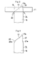
- Fig. 3 shows a state where the pin (14) is pressed into the link (11) in the present invention.
- the end of the pin (14) which is located at the front end side when the pint is pressed is formed in the shape so that the upper and lower edges of the pin (14) are pressed at the same time by deleting the upper edge of the pulley abutting part (17) which is located at the front end side when the pin (14) is pressed.
- a front end upper edge (19) to be previously fitted in the through hole (12) of the link (11) when the pin is pressed and a front end lower edge (20) to be fitted in the through hole (12) of the link (11) in the last instance when the pin is pressed are located at the end of each pin (14), since its end faces are made into the inclined surfaces (17a) and (18a) corresponding to the shapes of the sheaves contacting the end faces.
- the pressing margin of the upper edge (19) of the front end located near the front end side rather than the front end lower edge (20) is defined as zero. Accordingly, concentration of stresses in (31a) of Fig.
- the pin (14) can be easily obtained by obtaining the pin having the same shape as the conventional one in the same method as the conventional method, and then, performing a polishing process so as to make the upper edge at the front end (19) into a no-pressed part.
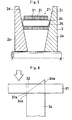
- an inclined face (21a) having a pressing margin which gradually increases is provided at a border between an upper edge (21) of the pulley abutting part (17) which is located at the front end side when the pin is pressed and the upper edge of the link holding part (16), and an inclined face (22a) having a pressing margin which gradually increases is also provided at a border between a lower edge (22) of the pulley abutting part (17) which is located at the front end side when the pin is pressed and the lower edge of the link holding part (16).
- the pin can be more easily pressed and concentration of stresses when the pin is pressed is relaxed.
- the pin (14) according to the present embodiment can be obtained by polishing the inclined face (21a) located at the upper edge of the front end and the inclined face (22a) located at the lower edge of the front end by the same grind stone, so that this pin can be manufactured without increase in labor.
- the configuration of pressing can be also applied to a chain (a chain in which the lengths of the first pin and the second pin are the same and both of them contact the sheave faces) which transmits a power by contacting the sheave faces and includes the second pin instead of the above-described interpiece (15), and to other various types of power transmission chains.
Landscapes
- Engineering & Computer Science (AREA)
- General Engineering & Computer Science (AREA)
- Mechanical Engineering (AREA)
- Transmissions By Endless Flexible Members (AREA)
- Devices For Conveying Motion By Means Of Endless Flexible Members (AREA)
Applications Claiming Priority (1)
| Application Number | Priority Date | Filing Date | Title |
|---|---|---|---|
| JP2005221569A JP2007032820A (ja) | 2005-07-29 | 2005-07-29 | 動力伝達チェーンおよび動力伝達装置 |
Publications (3)
| Publication Number | Publication Date |
|---|---|
| EP1748220A2 true EP1748220A2 (de) | 2007-01-31 |
| EP1748220A3 EP1748220A3 (de) | 2007-06-06 |
| EP1748220B1 EP1748220B1 (de) | 2008-09-10 |
Family
ID=37307214
Family Applications (1)
| Application Number | Title | Priority Date | Filing Date |
|---|---|---|---|
| EP06015815A Ceased EP1748220B1 (de) | 2005-07-29 | 2006-07-28 | Treibkette und Treibvorrichtung |
Country Status (4)
| Country | Link |
|---|---|
| US (1) | US7806794B2 (de) |
| EP (1) | EP1748220B1 (de) |
| JP (1) | JP2007032820A (de) |
| DE (1) | DE602006002678D1 (de) |
Families Citing this family (8)
| Publication number | Priority date | Publication date | Assignee | Title |
|---|---|---|---|---|
| JP4803423B2 (ja) * | 2005-10-14 | 2011-10-26 | 株式会社ジェイテクト | 動力伝達チェーンおよびこれを備える動力伝達装置 |
| US20070298921A1 (en) * | 2006-06-02 | 2007-12-27 | Luk Lamellen Und Kupplungsbau Beteiligungs Kg | Plate-link chain and rocker member for a belt-driven conical-pulley transmission |
| JP4923799B2 (ja) * | 2006-07-13 | 2012-04-25 | 株式会社ジェイテクト | 動力伝達チェーンおよび動力伝達装置 |
| WO2008069319A1 (ja) | 2006-12-08 | 2008-06-12 | Jtekt Corporation | 動力伝達チェーンおよび動力伝達装置 |
| US20100035713A1 (en) * | 2006-12-08 | 2010-02-11 | Yoshihisa Miura | Power transmission chain and power transmission device |
| JP5003184B2 (ja) | 2007-02-01 | 2012-08-15 | 株式会社ジェイテクト | 動力伝達チェーン用ピンおよびその製造方法 |
| CN109863240A (zh) | 2016-10-31 | 2019-06-07 | 通用电气公司 | 生物反应器组件 |
| DE112021001116A5 (de) * | 2020-02-19 | 2022-12-22 | Schaeffler Technologies AG & Co. KG | Wiegedruckstück für ein wiegedruckstückpaar einer laschenkette |
Citations (1)
| Publication number | Priority date | Publication date | Assignee | Title |
|---|---|---|---|---|
| JP2004301257A (ja) | 2003-03-31 | 2004-10-28 | Koyo Seiko Co Ltd | 動力伝達チェーン及びそれを用いた動力伝達装置 |
Family Cites Families (14)
| Publication number | Priority date | Publication date | Assignee | Title |
|---|---|---|---|---|
| DE2356289C2 (de) * | 1973-11-10 | 1975-06-26 | P.I.V. Antrieb, Werner Reimers Kg, 6380 Bad Homburg | Laschenkette für Kegelscheibengetriebe |
| JPS6192309A (ja) * | 1984-10-12 | 1986-05-10 | 本田技研工業株式会社 | 圧入部品 |
| JPS62234635A (ja) | 1986-04-02 | 1987-10-14 | Nissan Motor Co Ltd | 伝動ベルトの組立方法 |
| JP2672501B2 (ja) * | 1986-12-22 | 1997-11-05 | 株式会社東芝 | 話中応答電話装置 |
| NL1000294C2 (nl) | 1995-05-03 | 1996-11-05 | Gear Chain Ind Bv | Transmissieketting voor een kegeldrijfwerk. |
| JP3091451B1 (ja) * | 1999-06-14 | 2000-09-25 | 株式会社椿本チエイン | ロッカージョイントピン型サイレントチェーン |
| JP2001234983A (ja) * | 2000-02-24 | 2001-08-31 | Borg Warner Automotive Kk | 動力伝達用チェーンベルト |
| JP2001234982A (ja) * | 2000-02-24 | 2001-08-31 | Borg Warner Automotive Kk | 動力伝達用チェーンベルト |
| JP4424580B2 (ja) * | 2002-06-11 | 2010-03-03 | オイレス工業株式会社 | ブッシュ軸受 |
| EP1443242A3 (de) * | 2003-01-31 | 2005-02-09 | NTRK Co., Ltd. | Bauteil von Ketten für stufenlose, regelbare Getriebe |
| JP2004264568A (ja) * | 2003-02-28 | 2004-09-24 | Sumitomo Rubber Ind Ltd | シャフト付き弾性体ローラおよび製造方法 |
| JP2005054940A (ja) | 2003-08-06 | 2005-03-03 | Koyo Seiko Co Ltd | 動力伝達チェーン及びそれを用いた動力伝達装置 |
| US20050187057A1 (en) * | 2004-01-14 | 2005-08-25 | Koyo Seiko Co., Ltd. | Power transmission chain and power transmission apparatus using same |
| JP4525204B2 (ja) * | 2004-06-23 | 2010-08-18 | 株式会社エクォス・リサーチ | 伝動用無端ベルト |
-
2005
- 2005-07-29 JP JP2005221569A patent/JP2007032820A/ja active Pending
-
2006
- 2006-07-28 EP EP06015815A patent/EP1748220B1/de not_active Ceased
- 2006-07-28 US US11/494,739 patent/US7806794B2/en active Active
- 2006-07-28 DE DE602006002678T patent/DE602006002678D1/de not_active Expired - Lifetime
Patent Citations (1)
| Publication number | Priority date | Publication date | Assignee | Title |
|---|---|---|---|---|
| JP2004301257A (ja) | 2003-03-31 | 2004-10-28 | Koyo Seiko Co Ltd | 動力伝達チェーン及びそれを用いた動力伝達装置 |
Also Published As
| Publication number | Publication date |
|---|---|
| JP2007032820A (ja) | 2007-02-08 |
| US7806794B2 (en) | 2010-10-05 |
| DE602006002678D1 (de) | 2008-10-23 |
| US20070026988A1 (en) | 2007-02-01 |
| EP1748220B1 (de) | 2008-09-10 |
| EP1748220A3 (de) | 2007-06-06 |
Similar Documents
| Publication | Publication Date | Title |
|---|---|---|
| EP1878942B1 (de) | Kraftübertragungskette und Kraftübertragungsvorrichtung | |
| DE69920367T2 (de) | Schwerbelastbarer Treibkeilriemen | |
| EP1748220B1 (de) | Treibkette und Treibvorrichtung | |
| EP1555455A3 (de) | Treibkette und diese verwendende Antriebsvorrichtung | |
| JP5098348B2 (ja) | 動力伝達チェーンの製造に用いる圧入装置 | |
| EP1624225A3 (de) | Treibkette | |
| EP2053270A2 (de) | Kraftübertragungskette und Kraftübertragungsvorrichtung | |
| EP1840408A2 (de) | Kraftübertragungskette und Kraftübertragungssystem damit | |
| EP1698801A1 (de) | Kraftübertragungskette, kraftübertragungsvorrichtung und verfahren zur herstellung der kette | |
| EP1748221A2 (de) | Treibkette und Treibvorrichtung | |
| US8182384B2 (en) | Power transmission chain and power transmission apparatus | |
| JP5003184B2 (ja) | 動力伝達チェーン用ピンおよびその製造方法 | |
| EP1439322A3 (de) | Zahntreibriemen mit metallischem Kern, damit versehenes Getriebe und Herstellungsverfahren des Riemens | |
| EP1985890A2 (de) | Kraftübertragungskette und Kraftübertragungsvorrichtung | |
| EP1801454A2 (de) | Kraftübertragungskette, Verfahren zu ihrer Herstellung und Kraftübertragungsvorrichtung | |
| JP2009154164A (ja) | 動力伝達チェーンの製造方法および製造装置 | |
| JP2007170618A (ja) | 無段変速機 | |
| JPH04248043A (ja) | 高負荷伝動用vベルト | |
| JP2011200874A (ja) | 動力伝達チェーンの製造方法 | |
| KR20080077375A (ko) | 동력 전달 체인 및 동력 전달 장치 | |
| JP5640348B2 (ja) | 動力伝達チェーンの製造方法 | |
| JP2009045668A (ja) | 動力伝達チェーン用リンクの製造方法、動力伝達チェーンおよび動力伝達装置 | |
| JP2015150569A (ja) | 動力伝達チェーンの製造方法 | |
| JP2009222103A (ja) | 動力伝達チェーンおよび動力伝達装置 | |
| JP2006046497A (ja) | 動力伝達チェーンおよびこれを備える動力伝達装置 |
Legal Events
| Date | Code | Title | Description |
|---|---|---|---|
| PUAI | Public reference made under article 153(3) epc to a published international application that has entered the european phase |
Free format text: ORIGINAL CODE: 0009012 |
|
| AK | Designated contracting states |
Kind code of ref document: A2 Designated state(s): AT BE BG CH CY CZ DE DK EE ES FI FR GB GR HU IE IS IT LI LT LU LV MC NL PL PT RO SE SI SK TR |
|
| AX | Request for extension of the european patent |
Extension state: AL BA HR MK YU |
|
| PUAL | Search report despatched |
Free format text: ORIGINAL CODE: 0009013 |
|
| AK | Designated contracting states |
Kind code of ref document: A3 Designated state(s): AT BE BG CH CY CZ DE DK EE ES FI FR GB GR HU IE IS IT LI LT LU LV MC NL PL PT RO SE SI SK TR |
|
| AX | Request for extension of the european patent |
Extension state: AL BA HR MK YU |
|
| RIC1 | Information provided on ipc code assigned before grant |
Ipc: F16G 5/18 20060101AFI20061113BHEP Ipc: F16G 13/06 20060101ALI20070427BHEP Ipc: F16H 9/24 20060101ALI20070427BHEP |
|
| 17P | Request for examination filed |
Effective date: 20070914 |
|
| GRAP | Despatch of communication of intention to grant a patent |
Free format text: ORIGINAL CODE: EPIDOSNIGR1 |
|
| AKX | Designation fees paid |
Designated state(s): DE FR |
|
| GRAS | Grant fee paid |
Free format text: ORIGINAL CODE: EPIDOSNIGR3 |
|
| GRAA | (expected) grant |
Free format text: ORIGINAL CODE: 0009210 |
|
| AK | Designated contracting states |
Kind code of ref document: B1 Designated state(s): DE FR |
|
| REF | Corresponds to: |
Ref document number: 602006002678 Country of ref document: DE Date of ref document: 20081023 Kind code of ref document: P |
|
| PLBE | No opposition filed within time limit |
Free format text: ORIGINAL CODE: 0009261 |
|
| STAA | Information on the status of an ep patent application or granted ep patent |
Free format text: STATUS: NO OPPOSITION FILED WITHIN TIME LIMIT |
|
| 26N | No opposition filed |
Effective date: 20090611 |
|
| REG | Reference to a national code |
Ref country code: FR Ref legal event code: PLFP Year of fee payment: 11 |
|
| REG | Reference to a national code |
Ref country code: FR Ref legal event code: PLFP Year of fee payment: 12 |
|
| REG | Reference to a national code |
Ref country code: FR Ref legal event code: PLFP Year of fee payment: 13 |
|
| PGFP | Annual fee paid to national office [announced via postgrant information from national office to epo] |
Ref country code: FR Payment date: 20230620 Year of fee payment: 18 |
|
| PGFP | Annual fee paid to national office [announced via postgrant information from national office to epo] |
Ref country code: DE Payment date: 20230531 Year of fee payment: 18 |
|
| REG | Reference to a national code |
Ref country code: DE Ref legal event code: R119 Ref document number: 602006002678 Country of ref document: DE |
|
| PG25 | Lapsed in a contracting state [announced via postgrant information from national office to epo] |
Ref country code: DE Free format text: LAPSE BECAUSE OF NON-PAYMENT OF DUE FEES Effective date: 20250201 |
|
| PG25 | Lapsed in a contracting state [announced via postgrant information from national office to epo] |
Ref country code: FR Free format text: LAPSE BECAUSE OF NON-PAYMENT OF DUE FEES Effective date: 20240731 |