EP1748231B1 - Übertragungssystem - Google Patents
Übertragungssystem Download PDFInfo
- Publication number
- EP1748231B1 EP1748231B1 EP06023007A EP06023007A EP1748231B1 EP 1748231 B1 EP1748231 B1 EP 1748231B1 EP 06023007 A EP06023007 A EP 06023007A EP 06023007 A EP06023007 A EP 06023007A EP 1748231 B1 EP1748231 B1 EP 1748231B1
- Authority
- EP
- European Patent Office
- Prior art keywords
- shaft
- engagement members
- gear wheel
- transmission system
- sets
- Prior art date
- Legal status (The legal status is an assumption and is not a legal conclusion. Google has not performed a legal analysis and makes no representation as to the accuracy of the status listed.)
- Expired - Lifetime
Links
- 230000005540 biological transmission Effects 0.000 title claims abstract description 57
- 230000001133 acceleration Effects 0.000 claims abstract description 12
- 230000008859 change Effects 0.000 claims abstract description 5
- 230000000694 effects Effects 0.000 claims abstract description 4
- 241000282472 Canis lupus familiaris Species 0.000 claims description 58
- 230000015572 biosynthetic process Effects 0.000 claims description 10
- 238000005755 formation reaction Methods 0.000 claims description 10
- 230000033001 locomotion Effects 0.000 claims description 10
- 230000014759 maintenance of location Effects 0.000 description 4
- 230000007246 mechanism Effects 0.000 description 4
- 230000009471 action Effects 0.000 description 2
- 230000008901 benefit Effects 0.000 description 2
- 239000000446 fuel Substances 0.000 description 2
- 238000000034 method Methods 0.000 description 2
- 230000007935 neutral effect Effects 0.000 description 2
- 230000000712 assembly Effects 0.000 description 1
- 238000000429 assembly Methods 0.000 description 1
- 230000000295 complement effect Effects 0.000 description 1
- 230000001419 dependent effect Effects 0.000 description 1
- XDDAORKBJWWYJS-UHFFFAOYSA-N glyphosate Chemical compound OC(=O)CNCP(O)(O)=O XDDAORKBJWWYJS-UHFFFAOYSA-N 0.000 description 1
- 230000002045 lasting effect Effects 0.000 description 1
- 238000005259 measurement Methods 0.000 description 1
- 238000003801 milling Methods 0.000 description 1
- 230000004048 modification Effects 0.000 description 1
- 238000012986 modification Methods 0.000 description 1
- 230000008569 process Effects 0.000 description 1
- 230000009467 reduction Effects 0.000 description 1
- 230000004044 response Effects 0.000 description 1
- 230000000452 restraining effect Effects 0.000 description 1
- 230000007704 transition Effects 0.000 description 1
Images


Classifications
-
- F—MECHANICAL ENGINEERING; LIGHTING; HEATING; WEAPONS; BLASTING
- F16—ENGINEERING ELEMENTS AND UNITS; GENERAL MEASURES FOR PRODUCING AND MAINTAINING EFFECTIVE FUNCTIONING OF MACHINES OR INSTALLATIONS; THERMAL INSULATION IN GENERAL
- F16D—COUPLINGS FOR TRANSMITTING ROTATION; CLUTCHES; BRAKES
- F16D23/00—Details of mechanically-actuated clutches not specific for one distinct type
- F16D23/02—Arrangements for synchronisation, also for power-operated clutches
-
- F—MECHANICAL ENGINEERING; LIGHTING; HEATING; WEAPONS; BLASTING
- F16—ENGINEERING ELEMENTS AND UNITS; GENERAL MEASURES FOR PRODUCING AND MAINTAINING EFFECTIVE FUNCTIONING OF MACHINES OR INSTALLATIONS; THERMAL INSULATION IN GENERAL
- F16D—COUPLINGS FOR TRANSMITTING ROTATION; CLUTCHES; BRAKES
- F16D23/00—Details of mechanically-actuated clutches not specific for one distinct type
- F16D23/02—Arrangements for synchronisation, also for power-operated clutches
- F16D23/04—Arrangements for synchronisation, also for power-operated clutches with an additional friction clutch
- F16D23/06—Arrangements for synchronisation, also for power-operated clutches with an additional friction clutch and a blocking mechanism preventing the engagement of the main clutch prior to synchronisation
-
- F—MECHANICAL ENGINEERING; LIGHTING; HEATING; WEAPONS; BLASTING
- F16—ENGINEERING ELEMENTS AND UNITS; GENERAL MEASURES FOR PRODUCING AND MAINTAINING EFFECTIVE FUNCTIONING OF MACHINES OR INSTALLATIONS; THERMAL INSULATION IN GENERAL
- F16H—GEARING
- F16H63/00—Control outputs from the control unit to change-speed- or reversing-gearings for conveying rotary motion or to other devices than the final output mechanism
- F16H63/02—Final output mechanisms therefor; Actuating means for the final output mechanisms
- F16H63/30—Constructional features of the final output mechanisms
-
- F—MECHANICAL ENGINEERING; LIGHTING; HEATING; WEAPONS; BLASTING
- F16—ENGINEERING ELEMENTS AND UNITS; GENERAL MEASURES FOR PRODUCING AND MAINTAINING EFFECTIVE FUNCTIONING OF MACHINES OR INSTALLATIONS; THERMAL INSULATION IN GENERAL
- F16D—COUPLINGS FOR TRANSMITTING ROTATION; CLUTCHES; BRAKES
- F16D11/00—Clutches in which the members have interengaging parts
- F16D11/08—Clutches in which the members have interengaging parts actuated by moving a non-rotating part axially
- F16D11/10—Clutches in which the members have interengaging parts actuated by moving a non-rotating part axially with clutching members movable only axially
-
- F—MECHANICAL ENGINEERING; LIGHTING; HEATING; WEAPONS; BLASTING
- F16—ENGINEERING ELEMENTS AND UNITS; GENERAL MEASURES FOR PRODUCING AND MAINTAINING EFFECTIVE FUNCTIONING OF MACHINES OR INSTALLATIONS; THERMAL INSULATION IN GENERAL
- F16D—COUPLINGS FOR TRANSMITTING ROTATION; CLUTCHES; BRAKES
- F16D21/00—Systems comprising a plurality of actuated clutches
- F16D21/02—Systems comprising a plurality of actuated clutches for interconnecting three or more shafts or other transmission members in different ways
- F16D21/04—Systems comprising a plurality of actuated clutches for interconnecting three or more shafts or other transmission members in different ways with a shaft carrying a number of rotatable transmission members, e.g. gears, each of which can be connected to the shaft by a clutching member or members between the shaft and the hub of the transmission member
-
- F—MECHANICAL ENGINEERING; LIGHTING; HEATING; WEAPONS; BLASTING
- F16—ENGINEERING ELEMENTS AND UNITS; GENERAL MEASURES FOR PRODUCING AND MAINTAINING EFFECTIVE FUNCTIONING OF MACHINES OR INSTALLATIONS; THERMAL INSULATION IN GENERAL
- F16H—GEARING
- F16H63/00—Control outputs from the control unit to change-speed- or reversing-gearings for conveying rotary motion or to other devices than the final output mechanism
- F16H63/02—Final output mechanisms therefor; Actuating means for the final output mechanisms
- F16H63/30—Constructional features of the final output mechanisms
- F16H2063/3093—Final output elements, i.e. the final elements to establish gear ratio, e.g. coupling sleeves or other means establishing coupling to shaft
-
- Y—GENERAL TAGGING OF NEW TECHNOLOGICAL DEVELOPMENTS; GENERAL TAGGING OF CROSS-SECTIONAL TECHNOLOGIES SPANNING OVER SEVERAL SECTIONS OF THE IPC; TECHNICAL SUBJECTS COVERED BY FORMER USPC CROSS-REFERENCE ART COLLECTIONS [XRACs] AND DIGESTS
- Y10—TECHNICAL SUBJECTS COVERED BY FORMER USPC
- Y10T—TECHNICAL SUBJECTS COVERED BY FORMER US CLASSIFICATION
- Y10T74/00—Machine element or mechanism
- Y10T74/19—Gearing
- Y10T74/19191—Alternating rotary
- Y10T74/19205—Clutchable gears
-
- Y—GENERAL TAGGING OF NEW TECHNOLOGICAL DEVELOPMENTS; GENERAL TAGGING OF CROSS-SECTIONAL TECHNOLOGIES SPANNING OVER SEVERAL SECTIONS OF THE IPC; TECHNICAL SUBJECTS COVERED BY FORMER USPC CROSS-REFERENCE ART COLLECTIONS [XRACs] AND DIGESTS
- Y10—TECHNICAL SUBJECTS COVERED BY FORMER USPC
- Y10T—TECHNICAL SUBJECTS COVERED BY FORMER US CLASSIFICATION
- Y10T74/00—Machine element or mechanism
- Y10T74/19—Gearing
- Y10T74/19219—Interchangeably locked
- Y10T74/19242—Combined gear and clutch
-
- Y—GENERAL TAGGING OF NEW TECHNOLOGICAL DEVELOPMENTS; GENERAL TAGGING OF CROSS-SECTIONAL TECHNOLOGIES SPANNING OVER SEVERAL SECTIONS OF THE IPC; TECHNICAL SUBJECTS COVERED BY FORMER USPC CROSS-REFERENCE ART COLLECTIONS [XRACs] AND DIGESTS
- Y10—TECHNICAL SUBJECTS COVERED BY FORMER USPC
- Y10T—TECHNICAL SUBJECTS COVERED BY FORMER US CLASSIFICATION
- Y10T74/00—Machine element or mechanism
- Y10T74/19—Gearing
- Y10T74/19219—Interchangeably locked
- Y10T74/19284—Meshing assisters
Definitions
- the present invention relates to transmission systems and selector mechanisms used in transmission systems to select a gear ratio, and in particular to dog-type transmission systems, according to the preamble of claims 1,23.
- a known dog-type transmission system is described in the closest prior art document WO 01/29440 .
- the transmission system disclosed in that document is particularly suited for use in racing vehicles.
- When changing gear using conventional manual gearboxes there is a torque interruption when a first gear is disengaged and a second gear is selected.
- torque interruption time In racing vehicles it is necessary to reduce torque interruption time to a minimum thereby maximizing the amount of time an engine drives the vehicle.
- Torque interruptions lasting tenths of a second between gear changes can have significant impact on a vehicle's performance and hence placing in a race.
- the transmission system of WO 01/29440 addresses this problem by using dog rings engageable with recess rings attached to first and second gears mounted on an input shaft, and an actuator for moving the dog rings into and out of engagement with the recess rings, such that the first gear is still engaged when the second gear is selected, thereby reducing the torque interruption time to nearly zero.
- WO 01/29440 One problem with the invention disclosed in WO 01/29440 is that significant backlash occurs when accelerating or decelerating in a particular gear.
- the backlash is acceptable to racing drivers since racing drivers are generally more skilled than road users and are more interested in vehicle performance rather than obtaining a smooth ride. Therefore the advantage of reducing the duration of torque interrupts provided by the invention of WO 01/29440 for racing drivers far outweighs the backlash experienced.
- a smooth ride is a more important criterion and therefore transmission systems with large amounts of backlash are unsuitable for the vast majority of vehicles.
- WO 01/29440 uses a spline configuration that leads to structural weakness and which requires the dog rings to be very strong to prevent them from breaking apart under operating conditions.
- a further structural weakness is the cantilevered configuration of the recess rings.
- the arrangement of the arcuate recesses formed in the ring causes problems for the dog rings to properly engage with the gear wheels.
- the actuator assembly is also bulky leading to large gear boxes.
- the present invention seeks to provide an improved transmission system that mitigates at least some of the aforementioned problems.
- the transmission system including first and second rotatable shafts, and means for transferring drive from one of the shafts to the other shaft including first and second gear wheels each rotatably mounted on the first shaft and having drive formations formed thereon, a selector assembly for selectively transmitting torque between the first shaft and the first gear wheel and between the first shaft and the second gear wheel, wherein the selector assembly includes an actuator assembly and first and second sets of engagement members that are moveable into and out of engagement with the first and second gear wheels independently of each other, said selector assembly being arranged such that when a driving force is transmitted, one of the first and second sets of engagement members drivingly engages the engaged gear wheel, and the other set of engagement members is then in an unloaded condition, wherein the actuator assembly is arranged to move the unloaded set of engagement members into driving engagement with the unengaged gear wheel to effect a gear change.
- the transmission system thereby performs accelerating up-shifts and braking down-shifts substantially without torque interruption.
- the first shaft is an input shaft and the second shaft is an output shaft and drive is transferred from the input shaft to the output shaft.
- the first shaft can be the output shaft and the second shaft is the input shaft.
- the selector assembly is arranged such that when a braking force is transmitted the first set of engagement members drivingly engages the engaged gear wheel, and the second set of engagement members is in an unloaded condition, and when a driving force is transmitted the second set of engagement members drivingly engages the engaged gear wheel, and the second set of engagement members is then in an unloaded condition.
- the actuator assembly is arranged to bias the loaded set of engagement members towards the unengaged gear wheel without disengaging the loaded set of engagement members from the engaged gear wheel.
- the first and second sets of engagement members are arranged to rotate, in use, with the first shaft.
- the selector assembly is arranged such that the first and second sets of engagement members can move axially relative to each other along the first shaft.
- the first and second sets of engagement members are axially aligned when both sets engage the first or second gear wheels, and preferably when in a neutral condition.
- the first and second sets of engagement members are axially offset during gear change operations.
- the selector assembly is arranged such that when the first and second sets of engagement members engage one of the first and second gear wheels the backlash when moving between acceleration and deceleration is less than or equal to four degrees.
- the drive formations on the first and second gear wheels comprise first and second groups of dogs respectively.
- the first and second groups of dogs each comprise between two and eight dogs, evenly distributed on the first and second gears respectively.
- the first and second groups of dogs each comprise between two and four dogs, and preferably three dogs.
- the drive formations on the first and second gear wheels do not extend beyond the outer diameter of the gear wheels.
- first and second sets of engagement members comprise between two and eight members.
- first and second sets of engagement members comprise between two and four members, and preferably three members.
- the first shaft includes keyways formed in its curved surface arranged such that the first and second sets of engagement members can slide axially along the keyways and to radially restrain the positions of the sets of engagement members.
- the cross-section of the keyways is one of T-shaped, slotted, and dovetailed.
- the actuator assembly includes at least one resiliently deformable means arranged to move at least one of the first and second sets of engagement members into engagement with the first and second gear wheels when the engagement members are in unloaded conditions.
- the at least one resiliently deformable means is arranged to bias at least one of the first and second sets of engagement members towards the first or second gear wheel when the engagement members are drivingly engaged with a gear wheel.
- the actuator assembly includes first and second resiliently deformable means connected to the first and second sets of engagement members respectively such that the first resiliently deformable means acts on the first set engagement members and the second resiliently deformable means acts on the second set engagement members.
- the at least one resiliently deformable means is connected to the first and second sets of engagement members such that the resiliently deformable means acts on both the first and second sets of engagement members.
- the members of the first and / or second sets of engagement members can perform limited axial movement relative to each other in the keyways.
- the resiliently deformable means is a spring, and preferably a disc spring.
- the disc spring includes a plurality of arms, each arm having a first part that extends circumferentially around a portion of the disc spring and a second part that extends substantially radially inwards.
- the actuator assembly includes a fork that is arranged to engage the resiliently deformable means to move it axially along the first shaft.
- the transmission system may further include third and fourth gears mounted on the first shaft and a second selector assembly to provide additional gear ratios between the first and second shafts.
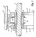
- Figure 1 shows a transmission system in accordance with the invention.
- the transmission system comprises an input shaft 1 having first and second gear wheels 3,5 mounted thereon, an output shaft 7 having third and fourth gear wheels 9,11 mounted thereon and a selector assembly 13.
- the first and second gear wheels 3,5 are rotatably mounted on the input shaft 1 and the third and fourth gear wheels 9,11 are fixedly mounted on the output shaft 7.
- the first and second gear wheels 3,5 mesh with third and fourth gear wheels 9,11 respectively to form first and second gear wheel pairs 15,17.
- Rotational drive may be transferred from the input shaft 1 to the output shaft 7 via either the first or second gear wheel pairs 15,17, with selection of the gear wheel pairs being determined by the position of the selector assembly 13.
- the selector assembly 13 engages first and second groups of drive formations 19,21 located on the first and second gear wheels 3,5 respectively.
- the drive formations each comprise groups of dogs.
- the first dog group 19 is located on one side of the first gear wheel 3.
- the dogs are preferably formed integrally with the first gear wheel, but this is not essential.
- the first dog group 19 comprises three dogs evenly circumferentially distributed about the gear face, i.e. the angle subtended between the centres of a pair of dogs is approximately 120° (see Figure 3 ).
- the second dog group 21 comprises three dogs and is similarly arranged on one side of the second gear wheel. Three dogs are used because this arrangement provides large engagement windows, that is the spaces between the dogs, to receive the selector assembly 13. Large engagement windows provide greater opportunities for the selector assembly to fully engage the gear wheels 3,5 before transmitting drive thereto. If the selector assembly 13 drives a gear wheel when only partially engaged it can lead to damage of the dogs and / or the selector assembly 13.
- the first and second gear wheels 3,5 are mounted spaced apart on the input shaft 1 on roller bearings 23,25 and are arranged such that the sides including the first and second dog groups face each other.
- the selector assembly 13 includes first and second sets of engagement bars 27,29 and an actuator assembly 31 in the form of a fork assembly 33 and a selector rod 35.
- the first and second sets of engagement bars 27,29 are mounted on the input shaft 1 between the first and second gear wheels 3,5.
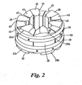
- the first set of engagement bars 27 comprises three bars 28 attached to a first connector ring, for example using grub screws.
- the first connector ring 37 holds the bars in a fixed arrangement.
- the bars 28 are evenly distributed about the inner circumference of the first connector ring such that their bases face inwards, and the bars 28 are arranged substantially parallel.
- the second set of engagement bars 29 comprises three bars 30 which are held in a similar fixed arrangement by a second connector ring 39.
- the first and second engagement bar sets 27,29 are mounted on the input shaft 1 between the first and second gear wheels 3,5.
- the sets of engagement bars 27,29 are arranged to rotate with the input shaft 1 but are able to slide axially along the shaft in response to a switching action of the actuator assembly 31.
- the input shaft 1 includes six keyways 41 formed in its curved surface with each engagement bar 28,30 having a complementary formation in its base.
- the arrangement of the bar sets 27,29 is such that bars of a particular set are located in alternate keyways 41 and the bar sets 27,29 can slide along the input shaft 1.
- Each bar set 27,29 moves as a unit and each bar set can move independently of the other.
- the second connector ring 39 slides over the first set of bars 27 and the first connector ring 37 slides over the second set of bars 29.
- Each bar 28 in the first bar set 27 has a first end 28a arranged to engage the first group of dogs 19 attached to the first gear wheel 3 and a second end 28b arranged to engage the second group of dogs 21 on the second gear wheel 5.
- the first and second ends 28a,28b typically have the same configuration but are opposite handed, such that the first end 28a is arranged to engage the first group of dogs 19 during deceleration of the first gear wheel 3 and the second end 28b is arranged to engage the second group of dogs 21 during acceleration of the second gear wheel 5, for example during engine braking in automotive applications.
- Each bar 30 in the second bar set 29 is similarly arranged, except that the first end 30a is arranged to engage the first group of dogs 19 during acceleration of the first gear wheel 3 and the second end 30b is arranged to engage the second group of dogs 21 during deceleration of the second gear wheel 5.
- the first and second ends 28a,30a,28b,30b of each bar include a substantially vertical face 43 for engaging dogs 19,21 and a ramp 45 that slopes in the direction of the engagement face 43 to ensure that the bars 28,30 disengage from the dogs 19,21 to prevent the transmission from locking up.
- the dogs engagement faces 43 of the first end 28a of the first set of bars 27 are adjacent the dog engagement faces 43 of the first end 30a of the second set of bars 29.
- the first and second sets of bars 27,29 are fully engaged with a gear a dog is located between each pair of adjacent engagement faces 43.
- the dimensions of the dogs 19,21 and the ends of the bars are preferably such that there is little movement of a dog between the engagement face 43 of the acceleration bar and the engagement face 43 of the deceleration bar when the gear moves from acceleration to deceleration, or vice versa, to ensure that there is little or no backlash in the gear.
- the bars are configured to be close to the input shaft 1 to prevent significant cantilever effects due to large radial distances of loaded areas thus reducing the potential for structural failure.
- the actuator assembly 31 is arranged such that the fork assembly 33 is mounted on the selector rod 35, and the selector rod is provided parallel to the input shaft 1 and adjacent thereto.
- the fork assembly 33 includes a fork 46 and first and second annular disc springs 47,49 mounted about the input shaft 1 (see Figure 1 ).
- the first and second disc springs 47,49 have three arms, with each arm having a first part that extends circumferentially around a part of the spring and a second part that extends radially inwards (see Figure 4 ).
- the fork 46 has a first pair of arcuate members 51 arranged to engage the first disc spring 47.
- the arcuate members 51 are arranged such that the first disc spring 47 can rotate with the input shaft 1 between the arcuate members 51 and such that axial movement of the fork 46 parallel to the input shaft 1 moves the arcuate members 51 and hence the first disc spring 47 axially along the shaft if the first disc spring 47 is free to move, or biases the first disc spring 47 to move in the same direction as the fork 46 if the first disc spring 47 is unable to move.
- the fork 46 has a second pair of arcuate members 53 arranged to engage and act upon the second disc spring 49 in a similar manner.
- the position of the fork 46 relative to the first and second gear wheels 3,5 can be adjusted by movement of the selector rod 35 in the axial direction.
- the inner edges of the first disc spring 47 are fixed to the bars 28 in the first bar set 27 and the inner edges of the second disc spring 49 are fixed to the bars 30 in the second bar set 29.
- the engagement bar sets 27,29 are likewise moved or biassed to move.
- Figure 5a shows the first and second bar sets 27,29 in a neutral position, that is, neither bar set is engaged with a gear wheel.
- Figure 5b shows the first and second bar sets moving into engagement with the first gear wheel 3 under the action of the fork 46.
- Figure 5c shows a condition when the first gear wheel 3 is fully engaged, that is, the bars 28,30 are interleaved with the first group of dogs 19.
- the selector rod 35 is located such that the fork 46 maintains the first and second bar sets 27,29 in engagement with the first gear wheel 3. Accordingly, power is transferred from the input shaft 1, to the first gear wheel 3 by the first bar set 27 when decelerating and the second bar set 29 when accelerating via the first group of dogs 19. Power is transmitted to the output shaft 7 put via the third gear wheel 9.
- the fork 46 also acts on the second disc spring 49 to bias the bars of the second bar set 29 to move towards the second gear wheel 5.
- the bars of the second bar set 29 are loaded, i.e. are driving the first gear wheel 3, they cannot be disengaged from the first gear wheel 3, and therefore the bars of the second bar set 29 remain stationary.
- a conventional dog-type transmission system has approximately 30 degrees of backlash.
- a typical transmission system for a car in accordance with the current invention has backlash of less than four degrees.
- Backlash is reduced by minimising the clearance required between an engagement member and a dog during a gear shift: that is, the clearance between the dog and the following engagement member (see measurement 'A' in Figure 5b ).
- the clearance between the dog and the following engagement member is in the range 0.5mm - 0.03mm and is typically less than 0.2mm.
- Backlash is also a function of the retention angle, that is, the angle of the engagement face 43, which is the same as the angle of the undercut on the engagement face of the dog.
- the retention angle influences whether there is relative movement between the dog and the engagement face 43. The smaller the retention angle, the less backlash that is experienced.
- the retention angle is typically between 2.5 and 15 degrees, and preferably is 15 degrees.
- the engagement surfaces 43 of the bars of the first bar set 27 are not loaded, whilst the engagement surfaces 43 of the bars of the second bar set 29 are loaded.
- the selector rod 35 is moved such that the fork 46 slides axially relative to the input shaft 1.
- the fork 46 acts on the first disc spring 47 attached to the first bar set 27, causing the bars of the first bar set 27 to slide axially in the keyways 41 along the input shaft 1 in the direction of the first gear wheel 3, thereby disengaging the first bar set 27 from the second gear wheel 5.
- the fork 5 also acts on the second disc spring 49 but since the bars of the second bar set 29 are loaded, i.e. they are drivingly engaged with the dogs 21 on the second gear wheel, the second bar set 29 remains stationary, however the second disc spring 49 is biassed by the fork 46 to move the second bar set 29 towards the first gear wheel 3.
- the bars of the first bar set 27 slide axially in the keyways 41, the bars 28 engage the dogs 19 on the first gear wheel and begin to drive the first gear wheel 3 such that energy is transmitted from the input shaft 1 to the output shaft 7 by way of the first gear wheel pair 15.
- the bars of the second bar set 29 cease to be loaded.
- the second disc spring 49 acts on the bars of the second bar set 29, causing it to slide axially within the keyways 41 along the input shaft 1 towards the first gear wheel 3, thereby completing disengagement of the second gear wheel 5.
- the second bar set 29 continues to slide within the keyways 41 along the input shaft 1 until it engages the first gear wheel 3, thereby completing engagement of the first gear wheel 3 with the input shaft 1.
- Kick-down shifts that is a gear shift from a higher gear ratio to a larger gear ratio but where acceleration takes place, for example when a vehicle is travelling up a hill and the driver selects a lower gear to accelerate up the hill, have a brief torque interruption to allow disengagement prior to the shift.
- a plurality of selector assemblies can be mounted on the input shaft with corresponding pairs of gear wheels to provide a larger number of gear ratios between the output shaft and the input shaft. It is also possible to have transmission systems with more than two shafts to provide additional gear ratios.
- the keyways 41 can be formed in a separate component from the input shaft which is then fixedly attached to the input shaft, for example by using a splined arrangement.
- the keyways 41 preferably have dovetailed profiles such that the bars are radially restrained within the keyways (see Figure 5 ).
- the keyways can have a slotted or T-shaped profile to radially restrain the bars. This provides a significant advantage since it obviates the need for the first and second connector rings 37,39 to connect the bars together in the first and second bar sets.
- This arrangement is preferred since it provides an improved means of restraining the radial position of the bars 28,30 relative to the input shaft 1, leading to greater structural integrity of the transmission system. Since the connector rings 37,39 are no longer required it is possible to reduce the length of the engagement bars 28,30 thereby producing more compact transmission systems.
- embodiments of the invention allow embodiments of the invention to be used having only one disc spring 147 (see Figure 7 ) connecting all six bars together, i.e. bars from the first and second sets, with the actuator arrangement being adapted accordingly.
- three of the bars would be loaded when the first gear is accelerating and three not loaded, and moving the fork to bias the disc spring towards the second gear will move the three unloaded bars out of engagement with the first gear wheel, leaving three bars still in engagement.
- the remaining three bars will disengage from the first gear wheel, and under the loading of the disc spring move into engagement with the second gear wheel.
- This configuration provides a highly compact arrangement leading to smaller, lighter gear boxes.
- the axial space between the first and second gears to accommodate the selector mechanism may be reduced to around 20mm for typical road car applications.
- Figure 5a shows a recesses 28c in the top of each bar of the first bar set and a recess 30c in the top of a bar from the second bar set.
- the recesses 28c,30c allow connections to be made between the bars of the first and second bar sets 27,29 with the arms of the first and second disc springs 47,49 respectively.
- the shape of the recesses 28c,30c is such that the recesses allow each spring arm to move to a non-perpendicular angle relative to the bars 28,30 during a gear shift.
- the recesses 28c,30c shown in Figure 5a are for a two disc spring configuration.
- the recesses 28c,30c are located more centrally along the length of the bars 28,30.
- the bars in a set can move a small amount relative to each other in the axial direction. This is because the only connection between the bars in a set is provided by a deformable disc spring. A single bar is attached to each disc spring arm and each arm can deform independently of the others, thereby allowing the relative movement between the bars. The bars in a set will nevertheless essentially move in unison.
- the number of dogs on each of the gear wheels is not limited to three, for example any practicable number of dogs can be used. It has been found that two to eight dogs are suitable for most applications.
- the number of bars in a bar set can be any practicable number but most preferably the number of bars in a set equals the number of dogs in a group.
- the transmission system can be used in any vehicle for example, road cars, racing cars, lorries, motorcycles, bicycles, earth removal vehicles such as bulldozers, and military vehicles.
- the system can also be used in any machine that has first and second rotatable bodies wherein drive is to be transmitted from one of the rotatable bodies to the other, for example in lathes and milling machines.
- the transmission system can be adapted such that the selector assembly and the first and second gear wheels are mounted on the output shaft and the fixed gear wheels are mounted on the input shaft.
Landscapes
- Engineering & Computer Science (AREA)
- General Engineering & Computer Science (AREA)
- Mechanical Engineering (AREA)
- Structure Of Transmissions (AREA)
- Gear-Shifting Mechanisms (AREA)
- Vehicle Body Suspensions (AREA)
- Mechanical Operated Clutches (AREA)
- Control Of Transmission Device (AREA)
- Arrangement And Driving Of Transmission Devices (AREA)
- Arrangement And Mounting Of Devices That Control Transmission Of Motive Force (AREA)
- Golf Clubs (AREA)
- Shafts, Cranks, Connecting Bars, And Related Bearings (AREA)
Claims (29)
- Übertragungssystem, das eine erste und eine zweite drehbare Welle (1, 7) und Mittel zum Weiterleiten des Antriebs von der einen der Welle zu der anderen Welle einschließt, einschließlich eines ersten und eines zweiten Getrieberades (3, 5), die jeweils drehbar auf der ersten Welle (1) angebracht sind, und einer Wahlschalterbaugruppe (13) zum selektiven Übertragen eines Drehmoments zwischen der ersten Welle (1) und dem ersten Getrieberad (3) und zwischen der ersten Welle (1) und dem zweiten Getrieberad, wobei die Wahlschalterbaugruppe (13) eine Stellantriebsbaugruppe (31) und einen ersten und einen zweiten Satz von Eingriffselementen (27, 29) einschließt, die dafür angeordnet sind, selektiv das erste und das zweite Getrieberad (3, 5) unabhängig voneinander für eine Drehung mit der ersten Welle (1) zu verriegeln, wobei die Wahlschalterbaugruppe (13) derart angeordnet ist, dass, wenn eine Antriebskraft übertragen wird, einer von dem ersten und dem zweiten Satz von Eingriffselementen (27, 29) ein Drehmoment zwischen dem eingerückten Getrieberad und der ersten Welle (1) überträgt und der andere Satz von Eingriffselementen dann in einem unbelasteten Zustand ist, wobei die Stellantriebsbaugruppe (31) dafür angeordnet ist, den unbelasteten Satz von Eingriffselementen zu verwenden, um das nicht eingerückte Getrieberad für eine Drehung mit der ersten Welle (1) zu verriegeln, um einen Gangwechsel zu bewirken, dadurch gekennzeichnet, dass die Wahlschalterbaugruppe (13) derart angeordnet ist, dass, wenn der erste und der zweite Satz von Eingriffselementen (27, 29) eines von dem ersten und dem zweiten Getrieberad (3, 5) in Eingriff nehmen, das Spiel beim Bewegen zwischen Beschleunigung und Verzögerung geringer als oder gleich vier Grad ist.
- Übertragungssystem nach Anspruch 1, wobei die Wahlschalterbaugruppe (13) derart angeordnet ist, dass, wenn eine Bremskraft übertragen wird, der erste Satz von Eingriffselementen (27) antreibend das eingerückte Getrieberad in Eingriff nimmt und der zweite Satz von Eingriffselementen (29) in einem unbelasteten Zustand ist, und wenn eine Antriebskraft übertragen wird, der zweite Satz von Eingriffselementen (29) antreibend das eingerückte Getrieberad in Eingriff nimmt und dann der zweite Satz von Eingriffselementen (29) in einem unbelasteten Zustand ist.
- Übertragungssystem nach Anspruch 1 oder 2, wobei die Stellantriebsbaugruppe (31) dafür angeordnet ist, den belasteten Satz von Eingriffselementen zu dem nicht eingerückten Getrieberad hin vorzuspannen, ohne den belasteten Satz von Eingriffselementen von dem ein eingerückten Getrieberad auszurücken.
- Übertragungssystem nach einem der vorhergehenden Ansprüche, wobei der erste und der zweite Satz von Eingriffselementen (27, 29) dafür angeordnet sind, sich bei Anwendung mit der ersten Welle (1) zu drehen.
- Übertragungssystem nach einem der vorhergehenden Ansprüche, wobei die erste Welle (1) eine Antriebswelle ist und die zweite Welle (7) eine Abtriebswelle ist und ein Antrieb von der Antriebswelle zu der Abtriebswelle weitergeleitet wird.
- Übertragungssystem nach einem der vorhergehenden Ansprüche, wobei das erste und das zweite Getrieberad (3, 5) an denselben geformte Antriebsformationen (19, 21) haben, wobei der erste und der zweite Satz von Eingriffselementen (27, 29) in und außer Eingriff mit dem ersten und dem zweiten Getrieberad (3, 5) bewegt werden können, um sie für eine Drehung mit der ersten Welle (1) zu verriegeln und die Getrieberäder antreibend in Eingriff zu nehmen.
- Übertragungssystem nach Anspruch 6, wobei die Antriebsformationen an dem ersten und dem zweiten Getrieberad (3, 5) eine erste bzw. eine zweite Gruppe von Mitnehmern (19, 21) umfassen.
- Übertragungssystem nach Anspruch 7, wobei die erste und die zweite Gruppe von Mitnehmern (19, 21) jeweils zwischen zwei und acht Mitnehmern, gleichmäßig an dem ersten bzw. dem zweiten Getrieberad verteilt, umfassen.
- Übertragungssystem nach Anspruch 8, wobei die erste und die zweite Gruppe von Mitnehmern (19, 21) jeweils zwischen zwei und vier Mitnehmern, und vorzugsweise drei Mitnehmer, umfassen.
- Übertragungssystem nach einem der vorhergehenden Ansprüche, wobei der erste und der zweite Satz von Eingriffselementen (27, 29) zwischen zwei und acht Elementen umfassen.
- Übertragungssystem nach Anspruch 10, wobei der erste und der zweite Satz von Eingriffselementen (27, 29) zwischen zwei und vier Elementen, und vorzugsweise drei Elemente, umfassen.
- Übertragungssystem nach einem der vorhergehenden Ansprüche, wobei die erste Welle (1) Keilnuten (41) einschließt, die derart angeordnet sind, dass der erste und der zweite Satz von Eingriffselementen (27, 29) in Axialrichtung längs der Keilnuten (41) gleiten können, und dass die Positionen der Sätze von Eingriffselementen in Radialrichtung eingeschränkt werden.
- Übertragungssystem nach Anspruch 12, wobei der Querschnitt der Keilnuten (41) entweder T-förmig, geschlitzt oder schwalbenschwanzförmig ist.
- Übertragungssystem nach einem der vorhergehenden Ansprüche, wobei die Stellantriebsbaugruppe (31) wenigstens ein elastisch verformbares Mittel (47, 49; 147) einschließt, das dafür angeordnet ist, wenigstens einen von dem ersten und dem zweiten Satz von Eingriffselementen (27, 29) in einen Eingriff mit dem ersten und dem zweiten Getrieberad (3, 5) zu bewegen, wenn die Eingriffselemente (27, 29) in unbelastetem Zustand sind.
- Übertragungssystem nach Anspruch 14, wobei das wenigstens eine elastisch verformbare Mittel (47, 49; 147) dafür angeordnet ist, wenigstens einen von dem ersten und dem zweiten Satz von Eingriffselementen zu dem ersten und dem zweiten Getrieberad (3, 5) hin vorzuspannen, wenn die Eingriffselemente (27, 29) antreibend in Eingriff mit einem Getrieberad sind.
- Übertragungssystem nach Anspruch 14 oder 15, wobei die Stellantriebsbaugruppe (31) ein erstes und ein zweites elastisch verformbares Mittel (47, 49) einschließt, die mit dem ersten bzw. dem zweiten Satz von Eingriffselementen (27, 29) verbunden sind derart, dass das erste elastisch verformbare Mittel (47) auf den ersten Satz von Eingriffselementen (27) einwirkt und das zweite elastisch verformbare Mittel (49) auf den zweiten Satz von Eingriffselementen (29) einwirkt.
- Übertragungssystem nach Anspruch 14 oder 15, wobei das wenigstens eine elastisch verformbare Mittel (147) mit dem ersten und dem zweiten Satz von Eingriffselementen (27, 29) verbunden ist derart, dass das elastisch verformbare Mittel (147) sowohl auf den ersten als auch auf den zweiten Satz von Eingriffselementen (27, 29) einwirkt.
- Übertragungssystem nach Anspruch 12 bis 17, wobei die Elemente (28, 30) des ersten und/oder des zweiten Satzes von Eingriffselementen in den Keilnuten (41) eine begrenzte Axialbewegung im Verhältnis zueinander ausführen können.
- Übertragungssystem nach einem der Ansprüche 12 bis 18, wobei das elastisch verformbare Mittel (47, 49; 147) eine Feder, und vorzugsweise eine Tellerfeder, ist.
- Übertragungssystem nach einem der Ansprüche bis 19, wobei die Tellerfeder mehrere Arme einschließt, wobei jeder Arm einen ersten Teil, der sich umlaufend um einen Abschnitt der Tellerfeder erstreckt, und einen zweiten Teil, der sich im Wesentlichen in Radialrichtung nach innen erstreckt, hat.
- Übertragungssystem nach einem der Ansprüche 13 bis 20, wobei die Stellantriebsbaugruppe (31) eine Gabel (46) einschließt, die dafür angeordnet ist, das wenigstens eine elastisch verformbare Mittel (47, 49; 147) in Eingriff zu nehmen, um das wenigstens eine in Radialrichtung verformbare Mittel (47, 49; 147) in Axialrichtung längs der ersten Welle (1) zu bewegen.
- Übertragungssystem nach einem der vorhergehenden Ansprüche, wobei die Antriebsformationen (19, 21) derart angeordnet sind, dass sie sich nicht über den Außendurchmesser der Getrieberäder hinaus erstrecken.
- Übertragungssystem, das eine erste Welle (1), ein erstes Übersetzungsverhältnis einschließlich eines ersten Getrieberades (3), das drehbar auf der ersten Welle (1) angebracht ist, ein zweites Übersetzungsverhältnis, eine Wahlschalterbaugruppe (13), die eine Stellantriebsbaugruppe (31) und einen ersten und einen zweiten Satz von Eingriffselementen (27, 29) hat, um selektiv ein Drehmoment zwischen der ersten Welle (1) und dem ersten Getrieberad (3) zu übertragen, wobei die Wahlschalterbaugruppe (13) dafür angeordnet ist, aus den folgenden Betriebsmodi auszuwählen: Verriegeln des ersten Getrieberades (3) für eine Drehung mit der ersten Welle (1) in einer Richtung im Uhrzeigersinn und entriegelt in einer Richtung gegen den Uhrzeigersinn; Verriegeln des ersten Getrieberades (3) für eine Drehung mit der ersten Welle (1) in der Richtung gegen den Uhrzeigersinn und entriegelt in der Richtung im Uhrzeigersinn; und Verriegeln des ersten Getrieberades (3) für eine Drehung mit der ersten Welle (1) in den Richtungen im Uhrzeigersinn und gegen den Uhrzeigersinn, dadurch gekennzeichnet, dass, wenn der erste und der zweite Satz von Eingriffselementen (27, 29) das erste Getrieberad (3) in Eingriff nehmen, das Spiel beim Bewegen zwischen Beschleunigung und Verzögerung geringer als oder gleich vier Grad ist.
- Übertragungssystem nach Anspruch 23, wobei die Wahlschalterbaugruppe (13) derart angeordnet ist, dass, wenn eine Antriebskraft übertragen wird, der eine von dem ersten und dem zweiten Satz von Eingriffselementen (27, 29) ein Drehmoment zwischen dem eingerückten Getrieberad und der ersten Welle (1) überträgt und der andere Satz von Eingriffselementen dann in einem unbelasteten Zustand ist, wobei die Stellantriebsbaugruppe (31) dafür angeordnet ist, den unbelasteten Satz von Eingriffselementen außer Eingriff mit dem eingerückten Getrieberad zu bewegen, um einen Gangwechsel einzuleiten.
- Übertragungssystem nach Anspruch 23 oder 24, wobei das zweite Übersetzungsverhältnis ein zweites Getrieberad (5), das drehbar auf der ersten Welle (1) angebracht ist, einschließt.
- Übertragungssystem nach Anspruch 25, wobei die Wahlschalterbaugruppe (13) dafür angeordnet ist, das zweite Getrieberad (5) aus den folgenden Betriebsmodi für eine Drehung mit der ersten Welle (1) wahlweise zu verriegeln: Verriegeln des zweiten Getrieberades (5) für eine Drehung mit der ersten Welle (1) in einer Richtung im Uhrzeigersinn und entriegelt in einer Richtung gegen den Uhrzeigersinn; Verriegeln des zweiten Getrieberades (5) für eine Drehung mit der ersten Welle (1) in der Richtung gegen den Uhrzeigersinn und entriegelt in der Richtung im Uhrzeigersinn; und Verriegeln des zweiten Getrieberades (5) für eine Drehung mit der ersten Welle (1) in den Richtungen im Uhrzeigersinn und gegen den Uhrzeigersinn, wobei, wenn der erste und der zweite Satz von Eingriffselementen (27, 29) das zweite Getrieberad (5) in Eingriff nehmen, das Spiel beim Bewegen zwischen Beschleunigung und Verzögerung geringer als oder gleich vier Grad ist.
- Übertragungssystem nach Anspruch 25 oder 26, wobei das erste und das zweite Getrieberad (3, 5) an denselben geformte Antriebsformationen (19, 21) haben, wobei der erste und der zweite Satz von Eingriffselementen (27, 29) in und außer Eingriff mit dem ersten und dem zweiten Getrieberad (3, 5) bewegt werden können, um sie für eine Drehung mit der ersten Welle (1) zu verriegeln und die Getrieberäder antreibend in Eingriff zu nehmen.
- Übertragungssystem nach einem der Ansprüche 23 bis 26, wobei die Wahlschalterbaugruppe (13) dafür angeordnet ist, den folgenden Betriebsmodus in Bezug auf das erste Getrieberad (3) auszuwählen: das erste Getrieberad (3) ist nicht verriegelt für eine Drehung mit der ersten Welle (1) in den Richtungen im Uhrzeigersinn oder gegen den Uhrzeigersinn.
- Übertragungssystem nach einem der Ansprüche 26 bis 28, wobei die Wahlschalterbaugruppe (13) dafür angeordnet ist, den folgenden Betriebsmodus in Bezug auf das zweite Getrieberad (5) auszuwählen: das zweite Getrieberad (5) ist nicht verriegelt für eine Drehung mit der ersten Welle (1) in den Richtungen im Uhrzeigersinn oder gegen den Uhrzeigersinn.
Priority Applications (1)
| Application Number | Priority Date | Filing Date | Title |
|---|---|---|---|
| PL06023007T PL1748231T3 (pl) | 2003-05-07 | 2004-05-07 | Układ przenoszenia napędu |
Applications Claiming Priority (2)
| Application Number | Priority Date | Filing Date | Title |
|---|---|---|---|
| GBGB0310482.5A GB0310482D0 (en) | 2003-05-07 | 2003-05-07 | Shaft engagement mechanism |
| EP04731665A EP1620665B1 (de) | 2003-05-07 | 2004-05-07 | Verfahren zur durchführung von kickdown-schaltung in einem getriebe |
Related Parent Applications (1)
| Application Number | Title | Priority Date | Filing Date |
|---|---|---|---|
| EP04731665A Division EP1620665B1 (de) | 2003-05-07 | 2004-05-07 | Verfahren zur durchführung von kickdown-schaltung in einem getriebe |
Publications (2)
| Publication Number | Publication Date |
|---|---|
| EP1748231A1 EP1748231A1 (de) | 2007-01-31 |
| EP1748231B1 true EP1748231B1 (de) | 2008-03-19 |
Family
ID=9957600
Family Applications (2)
| Application Number | Title | Priority Date | Filing Date |
|---|---|---|---|
| EP06023007A Expired - Lifetime EP1748231B1 (de) | 2003-05-07 | 2004-05-07 | Übertragungssystem |
| EP04731665A Expired - Lifetime EP1620665B1 (de) | 2003-05-07 | 2004-05-07 | Verfahren zur durchführung von kickdown-schaltung in einem getriebe |
Family Applications After (1)
| Application Number | Title | Priority Date | Filing Date |
|---|---|---|---|
| EP04731665A Expired - Lifetime EP1620665B1 (de) | 2003-05-07 | 2004-05-07 | Verfahren zur durchführung von kickdown-schaltung in einem getriebe |
Country Status (17)
| Country | Link |
|---|---|
| US (1) | US7770480B2 (de) |
| EP (2) | EP1748231B1 (de) |
| JP (1) | JP4732335B2 (de) |
| KR (1) | KR101205988B1 (de) |
| CN (2) | CN101280825A (de) |
| AT (2) | ATE389835T1 (de) |
| AU (1) | AU2004236472A1 (de) |
| BR (1) | BRPI0409999B1 (de) |
| CA (1) | CA2524987A1 (de) |
| DE (2) | DE602004028352D1 (de) |
| EA (1) | EA007509B1 (de) |
| ES (1) | ES2303304T3 (de) |
| GB (1) | GB0310482D0 (de) |
| MX (1) | MXPA05011984A (de) |
| PL (1) | PL1748231T3 (de) |
| WO (1) | WO2004099654A1 (de) |
| ZA (1) | ZA200509832B (de) |
Cited By (1)
| Publication number | Priority date | Publication date | Assignee | Title |
|---|---|---|---|---|
| DE102016223123A1 (de) | 2016-11-23 | 2018-05-24 | Schaeffler Technologies AG & Co. KG | Antriebsstrang mit zugunterbrechungsfreiem Getriebe und Schutzeinrichtung |
Families Citing this family (45)
| Publication number | Priority date | Publication date | Assignee | Title |
|---|---|---|---|---|
| GB0310482D0 (en) | 2003-05-07 | 2003-06-11 | Zero Shift Ltd | Shaft engagement mechanism |
| BRPI0412454B1 (pt) | 2003-07-08 | 2017-02-14 | Zeroshift Ltd | sistema de transmissão |
| GB0321824D0 (en) | 2003-09-18 | 2003-10-15 | Zeroshift Ltd | Electromagnetic engagement mechanism |
| GB0504628D0 (en) | 2005-03-05 | 2005-04-13 | Zeroshift Ltd | Transmission layout |
| GB0609333D0 (en) | 2006-05-11 | 2006-06-21 | Zeroshift Ltd | Engagement member actuator control |
| WO2006123128A1 (en) * | 2005-05-14 | 2006-11-23 | Zeroshift Limited | Transmission system with safety device |
| GB0510129D0 (en) | 2005-05-18 | 2005-06-22 | Zeroshift Ltd | Sequential hub layout |
| DE102006028479B4 (de) * | 2006-03-07 | 2012-06-06 | Deere & Company | Getriebeschaltstelle zum Herstellen einer drehfesten Verbindung zwischen mindestens einem Zahnrad und einer Welle |
| EP1867898A1 (de) * | 2006-06-14 | 2007-12-19 | Peugeot Citroën Automobiles S.A. | Robotisiertes Drehmomentschaltgetriebe |
| FR2902482B1 (fr) | 2006-06-14 | 2009-04-03 | Peugeot Citroen Automobiles Sa | Boite de vitesse robotisee a changement de vitesses sous couple |
| GB0623292D0 (en) * | 2006-11-22 | 2007-01-03 | Zeroshift Ltd | Transmission system |
| GB0702548D0 (en) | 2007-02-09 | 2007-03-21 | Zeroshift Ltd | Gearbox |
| FR2914976B1 (fr) | 2007-04-12 | 2009-07-10 | Peugeot Citroen Automobiles Sa | Grille de commande de vitesses pour vehicule et boite de vitesses equipee d'une telle grille |
| FR2928191B1 (fr) * | 2008-03-03 | 2010-04-30 | Peugeot Citroen Automobiles Sa | Boite de vitesses a derivation de couple par un rapport superieur comprenant au moins deux arbres secondaires et procedes de changement de rapport montant et descendant associes |
| JP5142789B2 (ja) * | 2008-03-31 | 2013-02-13 | 本田技研工業株式会社 | 多段変速機 |
| JP5184942B2 (ja) * | 2008-03-31 | 2013-04-17 | 本田技研工業株式会社 | 多段変速機 |
| JP5036613B2 (ja) * | 2008-03-31 | 2012-09-26 | 本田技研工業株式会社 | 多段変速機 |
| JP5386100B2 (ja) * | 2008-03-31 | 2014-01-15 | 本田技研工業株式会社 | 多段変速機 |
| JP5086870B2 (ja) * | 2008-03-31 | 2012-11-28 | 本田技研工業株式会社 | 多段変速機 |
| JP5049183B2 (ja) | 2008-03-31 | 2012-10-17 | 本田技研工業株式会社 | 多段変速機 |
| CN101806359B (zh) * | 2010-04-27 | 2012-07-04 | 广州汽车集团股份有限公司 | 一种换挡时无动力传输中断的有级式机械变速器 |
| JP5658068B2 (ja) * | 2011-03-25 | 2015-01-21 | 富士重工業株式会社 | 変速装置 |
| GB201109100D0 (en) | 2011-05-27 | 2011-07-13 | Zeroshift Ltd | Transmission system |
| WO2013091036A1 (pt) * | 2011-12-20 | 2013-06-27 | Weg Equipamentos Elétricos S.A., - Motores | Sistema de transmissão de torque entre eixo acionador e cubo acionado de máquina elétricas girantes |
| GB2506199A (en) * | 2012-09-25 | 2014-03-26 | Qinetiq Ltd | Drive member selection mechanism having torque transmitting projections on each face |
| CN105339202B (zh) * | 2013-03-15 | 2017-11-28 | 艾里逊变速箱公司 | 变速器旁通离合器 |
| JP6072715B2 (ja) * | 2014-03-05 | 2017-02-01 | 本田技研工業株式会社 | 無段変速機 |
| GB2538695A (en) * | 2014-10-10 | 2016-11-30 | Qinetiq Ltd | Gearbox improvements |
| JP6605882B2 (ja) | 2015-08-21 | 2019-11-13 | トヨタ自動車株式会社 | 変速機 |
| GB201605063D0 (en) * | 2016-03-24 | 2016-05-11 | Qinetiq Ltd | A transmission |
| DE102016207103B4 (de) * | 2016-04-27 | 2018-06-07 | Schaeffler Technologies AG & Co. KG | Getriebe mit Kupplung und unterbrechungsfrei schaltbarer Schalteinheit zum Schalten zwischen den Getriebeeingangswellen |
| DE102016208932A1 (de) | 2016-05-24 | 2017-11-30 | Schaeffler Technologies AG & Co. KG | Doppelkupplung mit unterbrechungsfrei schaltbarer Schalteinheit und Antriebsstrang mit Doppelkupplung |
| JP6654751B2 (ja) | 2016-09-14 | 2020-02-26 | トヨタ自動車株式会社 | 車両用変速機 |
| CN111406159B (zh) * | 2017-11-28 | 2022-06-14 | 达纳格拉齐亚诺有限责任公司 | 电磁操作的联接装置 |
| DE112018006290T5 (de) * | 2018-01-02 | 2020-10-08 | Ford Global Technologies, Llc | Hybridantrieb |
| JP7006373B2 (ja) * | 2018-02-26 | 2022-01-24 | トヨタ自動車株式会社 | 車両用変速機 |
| IT201800006191A1 (it) * | 2018-06-11 | 2019-12-11 | Veicolo stradale con cambio a singola frizione e relativo metodo di controllo | |
| GB2573592B (en) | 2018-12-19 | 2022-03-09 | Zeroshift Trans Limited | Transmission system |
| GB2574291B (en) | 2019-03-11 | 2022-03-09 | Zeroshift Trans Limited | Transmission system |
| GB2578559B (en) | 2020-02-04 | 2021-01-27 | Zeroshift Trans Limited | Drive train |
| DE102021204859A1 (de) * | 2021-05-12 | 2022-11-17 | Magna powertrain gmbh & co kg | Verfahren zur Hysteresekompensation bei einem Aktuator und einer durch diesen Aktuator verstellbaren Schaltgabel |
| WO2022264408A1 (ja) * | 2021-06-18 | 2022-12-22 | 株式会社ユニバンス | トルク伝達要素 |
| CN113738830A (zh) * | 2021-11-03 | 2021-12-03 | 杭州斯诺康技术有限公司 | 一种新能源汽车变速器及该变速器的防护壳体 |
| GB2611833B (en) | 2022-02-25 | 2026-03-18 | Zeroshift Trans Limited | Transmission system |
| FR3147520A1 (fr) | 2023-04-07 | 2024-10-11 | Psa Automobiles Sa | Transmission de vehicule electrique comprenant au moins deux rapports de vitesse |
Family Cites Families (47)
| Publication number | Priority date | Publication date | Assignee | Title |
|---|---|---|---|---|
| DE607182C (de) | 1934-12-19 | Julius Hermann Klemt | Zweigeschwindigkeitswechselgetriebe zum selbsttaetigen Ausgleich zwischen Antriebskraft und Belastung mit auf der treibenden Welle gegen Federdruck verschiebbarer Kupplung fuer die verschiedenen UEbersetzungen | |
| US2314042A (en) * | 1941-07-24 | 1943-03-16 | Borg Warner | Transmission control |
| FR1357748A (fr) * | 1963-02-26 | 1964-04-10 | Renault | Synchroniseur pour accouplement à crabotage |
| US3327822A (en) * | 1965-08-06 | 1967-06-27 | Bendix Corp | Electromagnetic clutch or brake |
| US3780840A (en) * | 1972-05-19 | 1973-12-25 | Carter H | Gear selector for a transmission |
| US3872737A (en) * | 1972-05-19 | 1975-03-25 | Thomas Hazel Beasley | Selector for a transmission |
| US3903738A (en) * | 1974-06-13 | 1975-09-09 | Gen Motors Corp | Rotating machinery torque sensing arrangement |
| FR2312693A1 (fr) | 1975-05-27 | 1976-12-24 | Leboime Pierre | Perfectionnement aux dispositifs interdisant le passage hors synchronisme des clabots de boites de vitesses |
| US4098380A (en) * | 1977-04-07 | 1978-07-04 | Thomas Dalton A | Gear selector mechanism |
| CH622322A5 (de) * | 1977-11-10 | 1981-03-31 | Maag Zahnraeder & Maschinen Ag | |
| US4241818A (en) * | 1978-10-30 | 1980-12-30 | Facet Enterprises, Inc. | Lightweight electromagnetic clutch with shock absorber |
| AU6430980A (en) | 1979-11-26 | 1981-06-04 | Automotive Products Ltd. | Dual clutch transmission |
| US4328719A (en) * | 1980-03-18 | 1982-05-11 | Caterpillar Tractor Co. | Micromotion multiplier |
| JPS57190149A (en) | 1981-05-20 | 1982-11-22 | Honda Motor Co Ltd | Speed changer for vehicle |
| US4592241A (en) * | 1982-09-08 | 1986-06-03 | Nippon Soken | Torque detector |
| GB2159897B (en) | 1984-05-17 | 1988-07-20 | Windsor Smith Claude P | Change speed gear train |
| FR2583489B1 (fr) | 1985-06-14 | 1987-08-14 | Renault Vehicules Ind | Dispositif electromagnetique de solidarisation d'un pignon avec son arbre dans une boite de vitesses |
| JPS63106429A (ja) * | 1986-10-21 | 1988-05-11 | Daikin Mfg Co Ltd | クラツチ |
| US5038632A (en) * | 1989-12-19 | 1991-08-13 | Dana Corporation | Transmission shift lever biasing assembly |
| ES2077453T3 (es) | 1992-08-26 | 1995-11-16 | Volkswagen Ag | Procedimiento y dispositivo para el acoplamiento y desacoplamiento regulador del embrague de marcha en la caja de cambios de un vehiculo. |
| US6061619A (en) * | 1992-09-09 | 2000-05-09 | Luk Lamellen Und Kupplungsbau Gmbh | Electronic clutch management |
| GB2319819B (en) | 1994-02-23 | 1998-10-07 | Luk Getriebe Systeme Gmbh | Control method for a torque transfer system and torque transfer system for carrying out the control method |
| GB2320537B (en) | 1994-02-23 | 1998-08-26 | Luk Getriebe Systeme Gmbh | Drive assembly incorporating an internal combustion engine |
| DE19504935A1 (de) * | 1994-02-23 | 1995-08-24 | Luk Getriebe Systeme Gmbh | Verfahren zum Steuern eines Drehmomenten-Übertragungssystems |
| US5517876A (en) * | 1994-08-04 | 1996-05-21 | Eaton Corporation | Transmission spring loaded shift device |
| JP3237419B2 (ja) * | 1994-10-21 | 2001-12-10 | トヨタ自動車株式会社 | 車両用クラッチ制御装置 |
| JPH0954002A (ja) * | 1995-08-19 | 1997-02-25 | Aisin Aw Co Ltd | トルク検出装置 |
| US5802915A (en) | 1996-05-23 | 1998-09-08 | Eaton Corporation | Transmission shifting mechanism with ball ramp actuator |
| KR100283294B1 (ko) * | 1998-05-13 | 2001-03-02 | 장태환 | 자동차엔진출력토오크의실시간측정장치 |
| CN1220997C (zh) * | 1998-05-22 | 2005-09-28 | 松下电器产业株式会社 | 电解电容器及其制造方法 |
| DE19851160A1 (de) * | 1998-11-06 | 2000-05-18 | Zf Batavia Llc | Einrichtung zur Steuerung eines Automatikgetriebes |
| AUPQ353499A0 (en) * | 1999-10-19 | 1999-11-11 | Preload International Limited | Improved transmission system |
| DE10007847A1 (de) * | 2000-02-21 | 2001-08-23 | Zahnradfabrik Friedrichshafen | Elektromagnetische Schalteinrichtung |
| JP2001280175A (ja) * | 2000-03-30 | 2001-10-10 | Hitachi Ltd | 歯車式機構を用いた自動変速機の制御装置及び方法 |
| US6891299B2 (en) * | 2000-05-03 | 2005-05-10 | Moteurs Leroy-Somer | Rotary electric machine having a flux-concentrating rotor and a stator with windings on teeth |
| FR2810713B1 (fr) | 2000-06-23 | 2002-10-31 | Renault | Procede et mecanisme de changement de vitesses sous couple |
| DE10037401B4 (de) | 2000-08-01 | 2009-10-08 | Daimler Ag | Schalteinrichtung |
| DE10151467A1 (de) * | 2001-10-18 | 2003-05-08 | Bayerische Motoren Werke Ag | Schaltgetriebe mit Verriegelungseinrichtung zur Verriegelung einzelner Gänge |
| JP4034089B2 (ja) * | 2002-03-07 | 2008-01-16 | 株式会社日立製作所 | 自動変速機のクリープ制御装置及び方法 |
| SE521538C2 (sv) | 2002-03-19 | 2003-11-11 | Scania Cv Ab | Arrangemang och förfarande för att medge urläggning av en växel i en växellåda |
| CN100350167C (zh) * | 2002-09-19 | 2007-11-21 | 卢克摩擦片和离合器两合公司 | 用于避免参考位置移动的方法及装置 |
| EP1460305A1 (de) | 2003-03-21 | 2004-09-22 | BorgWarner Inc. | Wechselgetriebe |
| GB0310482D0 (en) | 2003-05-07 | 2003-06-11 | Zero Shift Ltd | Shaft engagement mechanism |
| BRPI0412454B1 (pt) | 2003-07-08 | 2017-02-14 | Zeroshift Ltd | sistema de transmissão |
| GB0320703D0 (en) | 2003-09-04 | 2003-10-01 | Zeroshift Ltd | Improvements to dog engagement mechanisms |
| US7261379B2 (en) * | 2003-09-05 | 2007-08-28 | Dura Global Technologies, Inc. | Reclining vehicle seat hinge assembly |
| GB0321824D0 (en) | 2003-09-18 | 2003-10-15 | Zeroshift Ltd | Electromagnetic engagement mechanism |
-
2003
- 2003-05-07 GB GBGB0310482.5A patent/GB0310482D0/en not_active Ceased
-
2004
- 2004-05-07 ES ES06023007T patent/ES2303304T3/es not_active Expired - Lifetime
- 2004-05-07 AT AT06023007T patent/ATE389835T1/de not_active IP Right Cessation
- 2004-05-07 CA CA002524987A patent/CA2524987A1/en not_active Abandoned
- 2004-05-07 CN CNA2008101113660A patent/CN101280825A/zh active Pending
- 2004-05-07 US US10/555,728 patent/US7770480B2/en not_active Expired - Lifetime
- 2004-05-07 EA EA200501757A patent/EA007509B1/ru not_active IP Right Cessation
- 2004-05-07 MX MXPA05011984A patent/MXPA05011984A/es active IP Right Grant
- 2004-05-07 JP JP2006506229A patent/JP4732335B2/ja not_active Expired - Fee Related
- 2004-05-07 PL PL06023007T patent/PL1748231T3/pl unknown
- 2004-05-07 AU AU2004236472A patent/AU2004236472A1/en not_active Abandoned
- 2004-05-07 AT AT04731665T patent/ATE475825T1/de not_active IP Right Cessation
- 2004-05-07 KR KR1020057021142A patent/KR101205988B1/ko not_active Expired - Fee Related
- 2004-05-07 EP EP06023007A patent/EP1748231B1/de not_active Expired - Lifetime
- 2004-05-07 WO PCT/GB2004/001976 patent/WO2004099654A1/en not_active Ceased
- 2004-05-07 CN CNB2004800163357A patent/CN100507322C/zh not_active Expired - Lifetime
- 2004-05-07 BR BRPI0409999A patent/BRPI0409999B1/pt not_active IP Right Cessation
- 2004-05-07 EP EP04731665A patent/EP1620665B1/de not_active Expired - Lifetime
- 2004-05-07 DE DE602004028352T patent/DE602004028352D1/de not_active Expired - Lifetime
- 2004-05-07 DE DE602004012619T patent/DE602004012619T2/de not_active Expired - Lifetime
-
2005
- 2005-12-05 ZA ZA200509832A patent/ZA200509832B/en unknown
Cited By (1)
| Publication number | Priority date | Publication date | Assignee | Title |
|---|---|---|---|---|
| DE102016223123A1 (de) | 2016-11-23 | 2018-05-24 | Schaeffler Technologies AG & Co. KG | Antriebsstrang mit zugunterbrechungsfreiem Getriebe und Schutzeinrichtung |
Also Published As
| Publication number | Publication date |
|---|---|
| DE602004012619D1 (de) | 2008-04-30 |
| AU2004236472A1 (en) | 2004-11-18 |
| US7770480B2 (en) | 2010-08-10 |
| GB0310482D0 (en) | 2003-06-11 |
| JP4732335B2 (ja) | 2011-07-27 |
| DE602004028352D1 (de) | 2010-09-09 |
| US20060207362A1 (en) | 2006-09-21 |
| KR101205988B1 (ko) | 2012-11-28 |
| CN100507322C (zh) | 2009-07-01 |
| KR20060023118A (ko) | 2006-03-13 |
| DE602004012619T2 (de) | 2009-05-07 |
| EP1748231A1 (de) | 2007-01-31 |
| BRPI0409999B1 (pt) | 2017-02-07 |
| MXPA05011984A (es) | 2006-05-31 |
| EP1620665B1 (de) | 2010-07-28 |
| ES2303304T3 (es) | 2008-08-01 |
| JP2006525479A (ja) | 2006-11-09 |
| ATE475825T1 (de) | 2010-08-15 |
| CN101280825A (zh) | 2008-10-08 |
| EA200501757A1 (ru) | 2006-04-28 |
| ATE389835T1 (de) | 2008-04-15 |
| BRPI0409999A (pt) | 2006-05-09 |
| CN1806137A (zh) | 2006-07-19 |
| ZA200509832B (en) | 2006-09-27 |
| EA007509B1 (ru) | 2006-10-27 |
| PL1748231T3 (pl) | 2008-08-29 |
| EP1620665A1 (de) | 2006-02-01 |
| WO2004099654A1 (en) | 2004-11-18 |
| CA2524987A1 (en) | 2004-11-18 |
Similar Documents
| Publication | Publication Date | Title |
|---|---|---|
| EP1620665B1 (de) | Verfahren zur durchführung von kickdown-schaltung in einem getriebe | |
| EP1856423B1 (de) | Übertragungskonfiguration | |
| EP2230424B1 (de) | Getriebesystem | |
| EP2423527B1 (de) | Getriebeanordnung | |
| GB2464702A (en) | Transmission system with gear elements having hydraulic damping | |
| US20060281563A1 (en) | Coupling device for coupling rotatable bodies and transmission system including a coupling device | |
| US20080194370A1 (en) | Transmission System With Safety Device | |
| WO2008145979A1 (en) | Actuator system for a gear selector assembly and transmission including the actuator system | |
| WO2009068853A1 (en) | Transmission system | |
| WO2005008092A1 (en) | Mechanism for limiting the transmission of torque |
Legal Events
| Date | Code | Title | Description |
|---|---|---|---|
| PUAI | Public reference made under article 153(3) epc to a published international application that has entered the european phase |
Free format text: ORIGINAL CODE: 0009012 |
|
| AC | Divisional application: reference to earlier application |
Ref document number: 1620665 Country of ref document: EP Kind code of ref document: P |
|
| AK | Designated contracting states |
Kind code of ref document: A1 Designated state(s): AT BE BG CH CY CZ DE DK EE ES FI FR GB GR HU IE IT LI LU MC NL PL PT RO SE SI SK TR |
|
| AX | Request for extension of the european patent |
Extension state: AL HR LT LV MK |
|
| 17P | Request for examination filed |
Effective date: 20070608 |
|
| GRAP | Despatch of communication of intention to grant a patent |
Free format text: ORIGINAL CODE: EPIDOSNIGR1 |
|
| AKX | Designation fees paid |
Designated state(s): AT BE BG CH CY CZ DE DK EE ES FI FR GB GR HU IE IT LI LU MC NL PL PT RO SE SI SK TR |
|
| GRAS | Grant fee paid |
Free format text: ORIGINAL CODE: EPIDOSNIGR3 |
|
| GRAA | (expected) grant |
Free format text: ORIGINAL CODE: 0009210 |
|
| AC | Divisional application: reference to earlier application |
Ref document number: 1620665 Country of ref document: EP Kind code of ref document: P |
|
| AK | Designated contracting states |
Kind code of ref document: B1 Designated state(s): AT BE BG CH CY CZ DE DK EE ES FI FR GB GR HU IE IT LI LU MC NL PL PT RO SE SI SK TR |
|
| REG | Reference to a national code |
Ref country code: GB Ref legal event code: FG4D |
|
| REG | Reference to a national code |
Ref country code: CH Ref legal event code: EP |
|
| REF | Corresponds to: |
Ref document number: 602004012619 Country of ref document: DE Date of ref document: 20080430 Kind code of ref document: P |
|
| REG | Reference to a national code |
Ref country code: IE Ref legal event code: FG4D |
|
| REG | Reference to a national code |
Ref country code: RO Ref legal event code: EPE |
|
| REG | Reference to a national code |
Ref country code: SE Ref legal event code: TRGR |
|
| PGFP | Annual fee paid to national office [announced via postgrant information from national office to epo] |
Ref country code: CZ Payment date: 20071218 Year of fee payment: 5 |
|
| REG | Reference to a national code |
Ref country code: ES Ref legal event code: FG2A Ref document number: 2303304 Country of ref document: ES Kind code of ref document: T3 |
|
| PGFP | Annual fee paid to national office [announced via postgrant information from national office to epo] |
Ref country code: SK Payment date: 20080509 Year of fee payment: 5 Ref country code: RO Payment date: 20080418 Year of fee payment: 5 Ref country code: AT Payment date: 20080514 Year of fee payment: 5 |
|
| REG | Reference to a national code |
Ref country code: PL Ref legal event code: T3 |
|
| PG25 | Lapsed in a contracting state [announced via postgrant information from national office to epo] |
Ref country code: SI Free format text: LAPSE BECAUSE OF FAILURE TO SUBMIT A TRANSLATION OF THE DESCRIPTION OR TO PAY THE FEE WITHIN THE PRESCRIBED TIME-LIMIT Effective date: 20080319 |
|
| PGFP | Annual fee paid to national office [announced via postgrant information from national office to epo] |
Ref country code: PL Payment date: 20080506 Year of fee payment: 5 Ref country code: TR Payment date: 20080416 Year of fee payment: 5 |
|
| PG25 | Lapsed in a contracting state [announced via postgrant information from national office to epo] |
Ref country code: PT Free format text: LAPSE BECAUSE OF FAILURE TO SUBMIT A TRANSLATION OF THE DESCRIPTION OR TO PAY THE FEE WITHIN THE PRESCRIBED TIME-LIMIT Effective date: 20080827 |
|
| PGFP | Annual fee paid to national office [announced via postgrant information from national office to epo] |
Ref country code: IE Payment date: 20080515 Year of fee payment: 5 Ref country code: NL Payment date: 20080501 Year of fee payment: 5 |
|
| ET | Fr: translation filed | ||
| PG25 | Lapsed in a contracting state [announced via postgrant information from national office to epo] |
Ref country code: MC Free format text: LAPSE BECAUSE OF NON-PAYMENT OF DUE FEES Effective date: 20080531 |
|
| REG | Reference to a national code |
Ref country code: CH Ref legal event code: PL |
|
| PLBE | No opposition filed within time limit |
Free format text: ORIGINAL CODE: 0009261 |
|
| STAA | Information on the status of an ep patent application or granted ep patent |
Free format text: STATUS: NO OPPOSITION FILED WITHIN TIME LIMIT |
|
| PG25 | Lapsed in a contracting state [announced via postgrant information from national office to epo] |
Ref country code: LI Free format text: LAPSE BECAUSE OF NON-PAYMENT OF DUE FEES Effective date: 20080531 Ref country code: DK Free format text: LAPSE BECAUSE OF FAILURE TO SUBMIT A TRANSLATION OF THE DESCRIPTION OR TO PAY THE FEE WITHIN THE PRESCRIBED TIME-LIMIT Effective date: 20080319 Ref country code: CH Free format text: LAPSE BECAUSE OF NON-PAYMENT OF DUE FEES Effective date: 20080531 Ref country code: EE Free format text: LAPSE BECAUSE OF FAILURE TO SUBMIT A TRANSLATION OF THE DESCRIPTION OR TO PAY THE FEE WITHIN THE PRESCRIBED TIME-LIMIT Effective date: 20080319 |
|
| 26N | No opposition filed |
Effective date: 20081222 |
|
| PGFP | Annual fee paid to national office [announced via postgrant information from national office to epo] |
Ref country code: BE Payment date: 20081128 Year of fee payment: 5 |
|
| PG25 | Lapsed in a contracting state [announced via postgrant information from national office to epo] |
Ref country code: BG Free format text: LAPSE BECAUSE OF FAILURE TO SUBMIT A TRANSLATION OF THE DESCRIPTION OR TO PAY THE FEE WITHIN THE PRESCRIBED TIME-LIMIT Effective date: 20080619 |
|
| PG25 | Lapsed in a contracting state [announced via postgrant information from national office to epo] |
Ref country code: CY Free format text: LAPSE BECAUSE OF FAILURE TO SUBMIT A TRANSLATION OF THE DESCRIPTION OR TO PAY THE FEE WITHIN THE PRESCRIBED TIME-LIMIT Effective date: 20080319 |
|
| BERE | Be: lapsed |
Owner name: ZEROSHIFT LTD Effective date: 20090531 |
|
| PG25 | Lapsed in a contracting state [announced via postgrant information from national office to epo] |
Ref country code: CZ Free format text: LAPSE BECAUSE OF NON-PAYMENT OF DUE FEES Effective date: 20090507 Ref country code: AT Free format text: LAPSE BECAUSE OF NON-PAYMENT OF DUE FEES Effective date: 20090507 |
|
| NLV4 | Nl: lapsed or anulled due to non-payment of the annual fee |
Effective date: 20091201 |
|
| REG | Reference to a national code |
Ref country code: SK Ref legal event code: MM4A Ref document number: E 3537 Country of ref document: SK Effective date: 20090507 |
|
| PG25 | Lapsed in a contracting state [announced via postgrant information from national office to epo] |
Ref country code: NL Free format text: LAPSE BECAUSE OF NON-PAYMENT OF DUE FEES Effective date: 20091201 Ref country code: SK Free format text: LAPSE BECAUSE OF NON-PAYMENT OF DUE FEES Effective date: 20090507 Ref country code: FI Free format text: LAPSE BECAUSE OF FAILURE TO SUBMIT A TRANSLATION OF THE DESCRIPTION OR TO PAY THE FEE WITHIN THE PRESCRIBED TIME-LIMIT Effective date: 20080319 |
|
| PG25 | Lapsed in a contracting state [announced via postgrant information from national office to epo] |
Ref country code: IE Free format text: LAPSE BECAUSE OF NON-PAYMENT OF DUE FEES Effective date: 20090507 Ref country code: RO Free format text: LAPSE BECAUSE OF NON-PAYMENT OF DUE FEES Effective date: 20090507 |
|
| PG25 | Lapsed in a contracting state [announced via postgrant information from national office to epo] |
Ref country code: BE Free format text: LAPSE BECAUSE OF NON-PAYMENT OF DUE FEES Effective date: 20090531 |
|
| PG25 | Lapsed in a contracting state [announced via postgrant information from national office to epo] |
Ref country code: LU Free format text: LAPSE BECAUSE OF NON-PAYMENT OF DUE FEES Effective date: 20080507 Ref country code: HU Free format text: LAPSE BECAUSE OF FAILURE TO SUBMIT A TRANSLATION OF THE DESCRIPTION OR TO PAY THE FEE WITHIN THE PRESCRIBED TIME-LIMIT Effective date: 20080920 |
|
| REG | Reference to a national code |
Ref country code: PL Ref legal event code: LAPE |
|
| PG25 | Lapsed in a contracting state [announced via postgrant information from national office to epo] |
Ref country code: PL Free format text: LAPSE BECAUSE OF NON-PAYMENT OF DUE FEES Effective date: 20090507 |
|
| PG25 | Lapsed in a contracting state [announced via postgrant information from national office to epo] |
Ref country code: GR Free format text: LAPSE BECAUSE OF FAILURE TO SUBMIT A TRANSLATION OF THE DESCRIPTION OR TO PAY THE FEE WITHIN THE PRESCRIBED TIME-LIMIT Effective date: 20080620 |
|
| PG25 | Lapsed in a contracting state [announced via postgrant information from national office to epo] |
Ref country code: TR Free format text: LAPSE BECAUSE OF NON-PAYMENT OF DUE FEES Effective date: 20090507 |
|
| REG | Reference to a national code |
Ref country code: GB Ref legal event code: 732E Free format text: REGISTERED BETWEEN 20130221 AND 20130227 |
|
| REG | Reference to a national code |
Ref country code: FR Ref legal event code: PLFP Year of fee payment: 13 |
|
| REG | Reference to a national code |
Ref country code: FR Ref legal event code: PLFP Year of fee payment: 14 |
|
| REG | Reference to a national code |
Ref country code: GB Ref legal event code: 732E Free format text: REGISTERED BETWEEN 20171130 AND 20171206 |
|
| REG | Reference to a national code |
Ref country code: FR Ref legal event code: PLFP Year of fee payment: 15 |
|
| REG | Reference to a national code |
Ref country code: DE Ref legal event code: R082 Ref document number: 602004012619 Country of ref document: DE Representative=s name: KOENIG SZYNKA TILMANN VON RENESSE PATENTANWAEL, DE Ref country code: DE Ref legal event code: R081 Ref document number: 602004012619 Country of ref document: DE Owner name: ZEROSHIFT TRANSMISSIONS LTD., MILTON KEYNES, GB Free format text: FORMER OWNER: ZEROSHIFT LTD., MILTON KEYNES, GB |
|
| PGFP | Annual fee paid to national office [announced via postgrant information from national office to epo] |
Ref country code: SE Payment date: 20200527 Year of fee payment: 17 |
|
| PGFP | Annual fee paid to national office [announced via postgrant information from national office to epo] |
Ref country code: ES Payment date: 20200728 Year of fee payment: 17 |
|
| REG | Reference to a national code |
Ref country code: SE Ref legal event code: EUG |
|
| PG25 | Lapsed in a contracting state [announced via postgrant information from national office to epo] |
Ref country code: SE Free format text: LAPSE BECAUSE OF NON-PAYMENT OF DUE FEES Effective date: 20210508 |
|
| REG | Reference to a national code |
Ref country code: ES Ref legal event code: FD2A Effective date: 20220706 |
|
| PG25 | Lapsed in a contracting state [announced via postgrant information from national office to epo] |
Ref country code: ES Free format text: LAPSE BECAUSE OF NON-PAYMENT OF DUE FEES Effective date: 20210508 |
|
| PGFP | Annual fee paid to national office [announced via postgrant information from national office to epo] |
Ref country code: IT Payment date: 20230526 Year of fee payment: 20 Ref country code: FR Payment date: 20230523 Year of fee payment: 20 Ref country code: DE Payment date: 20230526 Year of fee payment: 20 |
|
| PGFP | Annual fee paid to national office [announced via postgrant information from national office to epo] |
Ref country code: GB Payment date: 20230530 Year of fee payment: 20 |
|
| REG | Reference to a national code |
Ref country code: DE Ref legal event code: R071 Ref document number: 602004012619 Country of ref document: DE |
|
| REG | Reference to a national code |
Ref country code: GB Ref legal event code: PE20 Expiry date: 20240506 |
|
| PG25 | Lapsed in a contracting state [announced via postgrant information from national office to epo] |
Ref country code: GB Free format text: LAPSE BECAUSE OF EXPIRATION OF PROTECTION Effective date: 20240506 |
|
| PG25 | Lapsed in a contracting state [announced via postgrant information from national office to epo] |
Ref country code: GB Free format text: LAPSE BECAUSE OF EXPIRATION OF PROTECTION Effective date: 20240506 |