EP1748249A2 - Fourniture de dioxide de carbone sans bulles - Google Patents
Fourniture de dioxide de carbone sans bulles Download PDFInfo
- Publication number
- EP1748249A2 EP1748249A2 EP06013862A EP06013862A EP1748249A2 EP 1748249 A2 EP1748249 A2 EP 1748249A2 EP 06013862 A EP06013862 A EP 06013862A EP 06013862 A EP06013862 A EP 06013862A EP 1748249 A2 EP1748249 A2 EP 1748249A2
- Authority
- EP
- European Patent Office
- Prior art keywords
- consumer
- liquid
- condenser
- carbon dioxide
- supply line
- Prior art date
- Legal status (The legal status is an assumption and is not a legal conclusion. Google has not performed a legal analysis and makes no representation as to the accuracy of the status listed.)
- Withdrawn
Links
Images
Classifications
-
- F—MECHANICAL ENGINEERING; LIGHTING; HEATING; WEAPONS; BLASTING
- F17—STORING OR DISTRIBUTING GASES OR LIQUIDS
- F17C—VESSELS FOR CONTAINING OR STORING COMPRESSED, LIQUEFIED OR SOLIDIFIED GASES; FIXED-CAPACITY GAS-HOLDERS; FILLING VESSELS WITH, OR DISCHARGING FROM VESSELS, COMPRESSED, LIQUEFIED, OR SOLIDIFIED GASES
- F17C6/00—Methods and apparatus for filling vessels not under pressure with liquefied or solidified gases
-
- F—MECHANICAL ENGINEERING; LIGHTING; HEATING; WEAPONS; BLASTING
- F17—STORING OR DISTRIBUTING GASES OR LIQUIDS
- F17C—VESSELS FOR CONTAINING OR STORING COMPRESSED, LIQUEFIED OR SOLIDIFIED GASES; FIXED-CAPACITY GAS-HOLDERS; FILLING VESSELS WITH, OR DISCHARGING FROM VESSELS, COMPRESSED, LIQUEFIED, OR SOLIDIFIED GASES
- F17C9/00—Methods or apparatus for discharging liquefied or solidified gases from vessels not under pressure
- F17C9/02—Methods or apparatus for discharging liquefied or solidified gases from vessels not under pressure with change of state, e.g. vaporisation
-
- F—MECHANICAL ENGINEERING; LIGHTING; HEATING; WEAPONS; BLASTING
- F17—STORING OR DISTRIBUTING GASES OR LIQUIDS
- F17C—VESSELS FOR CONTAINING OR STORING COMPRESSED, LIQUEFIED OR SOLIDIFIED GASES; FIXED-CAPACITY GAS-HOLDERS; FILLING VESSELS WITH, OR DISCHARGING FROM VESSELS, COMPRESSED, LIQUEFIED, OR SOLIDIFIED GASES
- F17C2221/00—Handled fluid, in particular type of fluid
- F17C2221/01—Pure fluids
- F17C2221/013—Carbon dioxide
-
- F—MECHANICAL ENGINEERING; LIGHTING; HEATING; WEAPONS; BLASTING
- F17—STORING OR DISTRIBUTING GASES OR LIQUIDS
- F17C—VESSELS FOR CONTAINING OR STORING COMPRESSED, LIQUEFIED OR SOLIDIFIED GASES; FIXED-CAPACITY GAS-HOLDERS; FILLING VESSELS WITH, OR DISCHARGING FROM VESSELS, COMPRESSED, LIQUEFIED, OR SOLIDIFIED GASES
- F17C2223/00—Handled fluid before transfer, i.e. state of fluid when stored in the vessel or before transfer from the vessel
- F17C2223/01—Handled fluid before transfer, i.e. state of fluid when stored in the vessel or before transfer from the vessel characterised by the phase
- F17C2223/0107—Single phase
- F17C2223/0123—Single phase gaseous, e.g. CNG, GNC
-
- F—MECHANICAL ENGINEERING; LIGHTING; HEATING; WEAPONS; BLASTING
- F17—STORING OR DISTRIBUTING GASES OR LIQUIDS
- F17C—VESSELS FOR CONTAINING OR STORING COMPRESSED, LIQUEFIED OR SOLIDIFIED GASES; FIXED-CAPACITY GAS-HOLDERS; FILLING VESSELS WITH, OR DISCHARGING FROM VESSELS, COMPRESSED, LIQUEFIED, OR SOLIDIFIED GASES
- F17C2223/00—Handled fluid before transfer, i.e. state of fluid when stored in the vessel or before transfer from the vessel
- F17C2223/03—Handled fluid before transfer, i.e. state of fluid when stored in the vessel or before transfer from the vessel characterised by the pressure level
- F17C2223/033—Small pressure, e.g. for liquefied gas
-
- F—MECHANICAL ENGINEERING; LIGHTING; HEATING; WEAPONS; BLASTING
- F17—STORING OR DISTRIBUTING GASES OR LIQUIDS
- F17C—VESSELS FOR CONTAINING OR STORING COMPRESSED, LIQUEFIED OR SOLIDIFIED GASES; FIXED-CAPACITY GAS-HOLDERS; FILLING VESSELS WITH, OR DISCHARGING FROM VESSELS, COMPRESSED, LIQUEFIED, OR SOLIDIFIED GASES
- F17C2225/00—Handled fluid after transfer, i.e. state of fluid after transfer from the vessel
- F17C2225/01—Handled fluid after transfer, i.e. state of fluid after transfer from the vessel characterised by the phase
- F17C2225/0107—Single phase
- F17C2225/013—Single phase liquid
-
- F—MECHANICAL ENGINEERING; LIGHTING; HEATING; WEAPONS; BLASTING
- F17—STORING OR DISTRIBUTING GASES OR LIQUIDS
- F17C—VESSELS FOR CONTAINING OR STORING COMPRESSED, LIQUEFIED OR SOLIDIFIED GASES; FIXED-CAPACITY GAS-HOLDERS; FILLING VESSELS WITH, OR DISCHARGING FROM VESSELS, COMPRESSED, LIQUEFIED, OR SOLIDIFIED GASES
- F17C2225/00—Handled fluid after transfer, i.e. state of fluid after transfer from the vessel
- F17C2225/01—Handled fluid after transfer, i.e. state of fluid after transfer from the vessel characterised by the phase
- F17C2225/0146—Two-phase
- F17C2225/0153—Liquefied gas, e.g. LPG, GPL
-
- F—MECHANICAL ENGINEERING; LIGHTING; HEATING; WEAPONS; BLASTING
- F17—STORING OR DISTRIBUTING GASES OR LIQUIDS
- F17C—VESSELS FOR CONTAINING OR STORING COMPRESSED, LIQUEFIED OR SOLIDIFIED GASES; FIXED-CAPACITY GAS-HOLDERS; FILLING VESSELS WITH, OR DISCHARGING FROM VESSELS, COMPRESSED, LIQUEFIED, OR SOLIDIFIED GASES
- F17C2225/00—Handled fluid after transfer, i.e. state of fluid after transfer from the vessel
- F17C2225/03—Handled fluid after transfer, i.e. state of fluid after transfer from the vessel characterised by the pressure level
- F17C2225/033—Small pressure, e.g. for liquefied gas
-
- F—MECHANICAL ENGINEERING; LIGHTING; HEATING; WEAPONS; BLASTING
- F17—STORING OR DISTRIBUTING GASES OR LIQUIDS
- F17C—VESSELS FOR CONTAINING OR STORING COMPRESSED, LIQUEFIED OR SOLIDIFIED GASES; FIXED-CAPACITY GAS-HOLDERS; FILLING VESSELS WITH, OR DISCHARGING FROM VESSELS, COMPRESSED, LIQUEFIED, OR SOLIDIFIED GASES
- F17C2225/00—Handled fluid after transfer, i.e. state of fluid after transfer from the vessel
- F17C2225/04—Handled fluid after transfer, i.e. state of fluid after transfer from the vessel characterised by other properties of handled fluid after transfer
- F17C2225/042—Localisation of the filling point
- F17C2225/046—Localisation of the filling point in the liquid
-
- F—MECHANICAL ENGINEERING; LIGHTING; HEATING; WEAPONS; BLASTING
- F17—STORING OR DISTRIBUTING GASES OR LIQUIDS
- F17C—VESSELS FOR CONTAINING OR STORING COMPRESSED, LIQUEFIED OR SOLIDIFIED GASES; FIXED-CAPACITY GAS-HOLDERS; FILLING VESSELS WITH, OR DISCHARGING FROM VESSELS, COMPRESSED, LIQUEFIED, OR SOLIDIFIED GASES
- F17C2227/00—Transfer of fluids, i.e. method or means for transferring the fluid; Heat exchange with the fluid
- F17C2227/03—Heat exchange with the fluid
- F17C2227/0337—Heat exchange with the fluid by cooling
- F17C2227/0341—Heat exchange with the fluid by cooling using another fluid
- F17C2227/0353—Heat exchange with the fluid by cooling using another fluid using cryocooler
-
- F—MECHANICAL ENGINEERING; LIGHTING; HEATING; WEAPONS; BLASTING
- F17—STORING OR DISTRIBUTING GASES OR LIQUIDS
- F17C—VESSELS FOR CONTAINING OR STORING COMPRESSED, LIQUEFIED OR SOLIDIFIED GASES; FIXED-CAPACITY GAS-HOLDERS; FILLING VESSELS WITH, OR DISCHARGING FROM VESSELS, COMPRESSED, LIQUEFIED, OR SOLIDIFIED GASES
- F17C2227/00—Transfer of fluids, i.e. method or means for transferring the fluid; Heat exchange with the fluid
- F17C2227/03—Heat exchange with the fluid
- F17C2227/0367—Localisation of heat exchange
- F17C2227/0388—Localisation of heat exchange separate
-
- F—MECHANICAL ENGINEERING; LIGHTING; HEATING; WEAPONS; BLASTING
- F17—STORING OR DISTRIBUTING GASES OR LIQUIDS
- F17C—VESSELS FOR CONTAINING OR STORING COMPRESSED, LIQUEFIED OR SOLIDIFIED GASES; FIXED-CAPACITY GAS-HOLDERS; FILLING VESSELS WITH, OR DISCHARGING FROM VESSELS, COMPRESSED, LIQUEFIED, OR SOLIDIFIED GASES
- F17C2260/00—Purposes of gas storage and gas handling
- F17C2260/03—Dealing with losses
- F17C2260/031—Dealing with losses due to heat transfer
-
- F—MECHANICAL ENGINEERING; LIGHTING; HEATING; WEAPONS; BLASTING
- F17—STORING OR DISTRIBUTING GASES OR LIQUIDS
- F17C—VESSELS FOR CONTAINING OR STORING COMPRESSED, LIQUEFIED OR SOLIDIFIED GASES; FIXED-CAPACITY GAS-HOLDERS; FILLING VESSELS WITH, OR DISCHARGING FROM VESSELS, COMPRESSED, LIQUEFIED, OR SOLIDIFIED GASES
- F17C2260/00—Purposes of gas storage and gas handling
- F17C2260/05—Improving chemical properties
- F17C2260/056—Improving fluid characteristics
-
- F—MECHANICAL ENGINEERING; LIGHTING; HEATING; WEAPONS; BLASTING
- F17—STORING OR DISTRIBUTING GASES OR LIQUIDS
- F17C—VESSELS FOR CONTAINING OR STORING COMPRESSED, LIQUEFIED OR SOLIDIFIED GASES; FIXED-CAPACITY GAS-HOLDERS; FILLING VESSELS WITH, OR DISCHARGING FROM VESSELS, COMPRESSED, LIQUEFIED, OR SOLIDIFIED GASES
- F17C2270/00—Applications
- F17C2270/05—Applications for industrial use
Definitions
- the invention relates to a method and a device for providing bubble-free, liquid carbon dioxide according to the preambles of claims 1 and 5.
- This supply has the disadvantage that it does not work at high outside temperatures (above the critical point of CO 2 ) works.
- a liquid sampling directly from a CO 2 bottle with dip tube or from a CO 2 cylinder racks with the dip tubes in the bottles a part of the liquid evaporates in the extraction hose or in the sampling line, whereby the cleaning effect is reduced.
- all piping areas that are separated with shut-off valves must be equipped with safety valves. The gas must be safely discharged to the outside. With large blow-off quantities is to be expected because the CO 2 is present as a liquid in the line. This type of construction is therefore relatively complicated and expensive.
- the object of the invention is therefore to propose a supply device and a supply method, which provide less expensive always bubble-free CO 2 .
- Characteristic of the invention is that gaseous CO 2 is used to supply the consumers. This gas is routed via normal supply lines to the consumption points. At the point of consumption or shortly before, the gaseous CO 2 is liquefied or condensed according to the invention by cooling in a condenser. The liquefied CO 2 is then supplied to the consumer via a short supply line. Due to the complete condensation and the subsequent subcooling of the CO 2 , for example, a lot of CO 2 snow is produced during the expansion in the consumer. Thereby, the cleaning effect when the CO 2 snow is used for cleaning, is greatly increased. It has been shown that the supply pressure can be below the normal CO 2 flask pressure. Instead of approx. 50 bar cylinder pressure, 10-30 bar line pressure is sufficient to achieve a good cleaning result.
- the CO 2 is supercooled in the condenser to avoid post-evaporation.
- the supercooling can be slight, ie 4-15 ° C, in order to avoid re-evaporation to the consumer safely.
- the line between the capacitor and the load should be as short as possible. It is preferably in the range between 100 and 300 cm. It can also be isolated. But does not have to, if the flow velocity is relatively high and the temperature difference is relatively low.
- the process is particularly suitable if a pressure-reducing nozzle is provided as a consumer, since controlled operation of the expansion nozzle is now possible when liquid carbon dioxide is always supplied.
- expansion nozzle is used to clean objects, e.g. for cleaning welding nozzles, such as MIG or MAG burners.
- These nozzles often adhere to splashes, particles or condensates, which must be removed as quickly as possible in order not to impair the cycle times of the production too much. Since the cleaning process sometimes takes less than a second (0.5 sec recommended by the manufacturer), it is important to be able to provide liquid phase from the beginning.
- An apparatus for carrying out the method according to the invention has a reservoir from which CO 2 is removed in gaseous form. Via the supply line, the CO 2 is fed in gaseous form to a condenser, which is located shortly before the consumer and liquefies the CO 2 and possibly subcooled.
- the distance between the capacitor and the load is as small as possible. It is preferably 100 to 300 cm in order to ensure a mobility of the consumer without the condenser must be moved with.
- the storage of the CO 2 can be carried out either in a CO 2 bottle, via CO 2 -bottle or a CO 2 tank in which the gas is liquefied and is then brought into the gaseous phase via a separate evaporator.
- the gas can also be taken from an existing CO 2 line, as it already exists in many welding companies.
- a pressure regulator can be provided between the storage container and the supply line, if desired.
- any conventional condenser for CO 2 can be used. Particular preference is given to using a condenser with an electrically operated cooling unit, since electric current is present practically at every workstation.
- a liquid CO 2 purification system is particularly preferably used, to which the CO 2 is supplied in liquid form.
- liquid CO 2 is released in a nozzle with a valve and is then blown as a mixture of snow gas onto an object to be cleaned.
- This article may, for example, be an MIG / MAG torch which is to be cleared of welding spray residues.
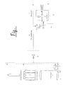
- FIG. 1 shows the principle of supplying a consumer for cleaning welding nozzles.
- the figure shows the CO 2 storage tank 1, in which liquid CO 2 is stored.
- An evaporator 2 can bring this liquid into the gaseous state.
- the CO 2 bundle 3 and the CO 2 bottle 4 are shown.
- a low-pressure tank is used and attached to the evaporator 2, a unit for increasing the pressure.
- Each of the three storage options then leads to the supply line 6, wherein this supply line 6, a pressure regulator 5 may be connected upstream.
- the supply line 6 leads to the condenser 8, in which the CO 2 is liquefied and is then passed via a CO 2 liquid line 9 to the consumer.
- the consumer here is the liquid CO 2 purification system 10 with a controllable valve and a pressure relief nozzle.
- the supply line 6 can optionally accomplish the supply of other consumers via a further line 7.
- a further line 7 for example, a welding shop.
- the CO2 which has been relieved in the release nozzle, is directed onto the welding torch, whereby adhering weld spatters are released by temperature stress and blown out with the gas jet.
- the liquid CO 2 purification system 10 is associated with a compressed air supply line 11, is optionally passed from the compressed air after CO2 blasting in the expansion nozzle. With the additional compressed air jet, remaining spatters can be blown out without the burner being too cold.
- the CO 2 is present in gaseous form in the relatively long supply line 6 and is liquefied in the condenser 8 shortly before the consumer 10.
- the CO 2 liquid line 9 is then relatively short: This eliminates the otherwise relatively large problems, liquid to supply CO 2 -leading lines with Abblasamba in the environment. The total supply is therefore cheaper than previous alternatives.
Landscapes
- Engineering & Computer Science (AREA)
- Mechanical Engineering (AREA)
- General Engineering & Computer Science (AREA)
- Filling Or Discharging Of Gas Storage Vessels (AREA)
- Cleaning In General (AREA)
- Treating Waste Gases (AREA)
- Carbon And Carbon Compounds (AREA)
Applications Claiming Priority (1)
| Application Number | Priority Date | Filing Date | Title |
|---|---|---|---|
| DE102005035432A DE102005035432A1 (de) | 2005-07-28 | 2005-07-28 | Bereitstellen blasenfreien Kohlendioxids |
Publications (2)
| Publication Number | Publication Date |
|---|---|
| EP1748249A2 true EP1748249A2 (fr) | 2007-01-31 |
| EP1748249A3 EP1748249A3 (fr) | 2010-09-01 |
Family
ID=37308820
Family Applications (1)
| Application Number | Title | Priority Date | Filing Date |
|---|---|---|---|
| EP06013862A Withdrawn EP1748249A3 (fr) | 2005-07-28 | 2006-07-04 | Fourniture de dioxide de carbone sans bulles |
Country Status (3)
| Country | Link |
|---|---|
| US (1) | US20070028648A1 (fr) |
| EP (1) | EP1748249A3 (fr) |
| DE (1) | DE102005035432A1 (fr) |
Families Citing this family (2)
| Publication number | Priority date | Publication date | Assignee | Title |
|---|---|---|---|---|
| DE102007038709A1 (de) | 2007-08-14 | 2009-02-19 | Linde Ag | Vorrichtung und Verfahren zum Verflüssigen von Prozessmedien |
| EP3500394A1 (fr) * | 2016-08-17 | 2019-06-26 | Stahlkontor GmbH + Co. KG | Procédé de soudage hybride laser/mig-mag d'éléments structuraux à grains fins et à haute résistance, avec une conduction thermique par induction ciblée |
Family Cites Families (10)
| Publication number | Priority date | Publication date | Assignee | Title |
|---|---|---|---|---|
| US1521385A (en) * | 1921-08-29 | 1924-12-30 | Messer Adolf | Device for the production of compressed oxygen from liquid oxygen |
| NL133404C (fr) * | 1963-08-02 | |||
| US3360944A (en) * | 1966-04-05 | 1968-01-02 | American Messer Corp | Gas liquefaction with work expansion of major feed portion |
| DE2929709A1 (de) * | 1979-07-21 | 1981-02-12 | Messer Griesheim Gmbh | Vorrichtung zum unterkuehlen von unter druck stehenden, tiefsiedenden verfluessigten gasen |
| CH656560A5 (de) * | 1982-03-19 | 1986-07-15 | Castolin Sa | Verfahren zum auftragen einer schutzschicht durch thermisches spritzen. |
| US4498303A (en) * | 1983-07-06 | 1985-02-12 | Heichberger Albert N | Carbon dioxide liquification system |
| JPH0622224B2 (ja) * | 1988-03-05 | 1994-03-23 | 大阪酸素工業株式会社 | パーティクルが少ないか又は含まない液化二酸化炭素の供給 |
| JP3277340B2 (ja) * | 1993-04-22 | 2002-04-22 | 日本酸素株式会社 | 半導体製造工場向け各種ガスの製造方法及び装置 |
| US6938439B2 (en) * | 2003-05-22 | 2005-09-06 | Cool Clean Technologies, Inc. | System for use of land fills and recyclable materials |
| US7069742B2 (en) * | 2004-01-19 | 2006-07-04 | Air Products And Chemicals, Inc. | High-pressure delivery system for ultra high purity liquid carbon dioxide |
-
2005
- 2005-07-28 DE DE102005035432A patent/DE102005035432A1/de not_active Withdrawn
-
2006
- 2006-07-04 EP EP06013862A patent/EP1748249A3/fr not_active Withdrawn
- 2006-07-27 US US11/493,963 patent/US20070028648A1/en not_active Abandoned
Also Published As
| Publication number | Publication date |
|---|---|
| EP1748249A3 (fr) | 2010-09-01 |
| DE102005035432A1 (de) | 2007-02-01 |
| US20070028648A1 (en) | 2007-02-08 |
Similar Documents
| Publication | Publication Date | Title |
|---|---|---|
| DE102014005936A1 (de) | Verfahren zum Verflüssigen einer Kohlenwasserstoff-reichen Fraktion | |
| EP3676529B1 (fr) | Procédé de remplissage d'un réservoir de frigorigène mobile comprenant un frigorigène cryogénique | |
| DE102007042158A1 (de) | Gasversorgungsanlage für einen mit gasförmigen Treibstoff betriebenen Verbrennungsmotor | |
| DE1601950A1 (de) | Verfahren und Vorrichtung zum Verfluessigen von natuerlichem Gas | |
| DE2337055A1 (de) | Verfahren und vorrichtung zur rueckgewinnung des in einem benzin-luft-gemisches enthaltenen benzins | |
| DE4445183A1 (de) | Betankungsverfahren für kryogene Flüssigkeiten | |
| DE69108973T2 (de) | Verfahren und Vorrichtung zur Produktion gasförmigen Stickstoffs und System zu dessen Bereitstellung. | |
| WO2023041401A1 (fr) | Dispositif et procédé pour remplir un réservoir de véhicule avec de l'hydrogène gazeux comprimé | |
| DE102006061251B4 (de) | Gasversorgungsanlage für einen Antrieb | |
| EP1748249A2 (fr) | Fourniture de dioxide de carbone sans bulles | |
| EP2899116A2 (fr) | Procédé et dispositif de réservoir pour la reliquéfaction et le refroidissement de gaz naturel liquide dans des systèmes de réservoir | |
| DE102007057979A1 (de) | Verfahren zum Befüllen eines Speicherbehälters mit kryogenem Wasserstoff | |
| DE102015009290A1 (de) | Verfahren zum Befüllen eines Kältemittelkreislaufs eines Kraftwagens | |
| EP2084722B1 (fr) | Procédé de refroidissement d'aimants supraconducteurs | |
| DE1170435B (de) | Verfahren zur Verfluessigung eines im fluessigen Zustand unter niedrigem Druck zu lagernden Gases | |
| EP3450819B1 (fr) | Procédé de remplissage d'un réservoir d'agent de refroidissement mobile d'un agent de refroidissement cryogénique | |
| DE102004043912A1 (de) | Bereitstellen blasenfreien Kohlendioxids | |
| DE102006046931A1 (de) | Indirekt arbeitendes Kühlsystem für ein Kühlfahrzeug | |
| DE19641647C1 (de) | Verfahren zur Versorgung von Abnehmern mit Erdgas und kryogenen Flüssigkeiten | |
| DE102005033252A1 (de) | Verfahren und Vorrichtung zur Kryokondensation | |
| DE102004028052A1 (de) | Verfahren zum Inbetriebnehmen eines Verflüssigungsprozesses | |
| DE102005038270A1 (de) | Verfahren zur Gewinnung von verdichtetem gasförmigen Wasserstoff und flüssigem Sauerstoff | |
| EP0503299B1 (fr) | Procédé et appareil pour la congélation de fluides dans les tuyaux | |
| EP2711601A2 (fr) | Procédé de remplissage d'un réservoir de fluide frigorifique d'un véhicule frigorifique et véhicule frigorifique | |
| DE102011115987B4 (de) | Erdgasverflüssigung |
Legal Events
| Date | Code | Title | Description |
|---|---|---|---|
| PUAI | Public reference made under article 153(3) epc to a published international application that has entered the european phase |
Free format text: ORIGINAL CODE: 0009012 |
|
| AK | Designated contracting states |
Kind code of ref document: A2 Designated state(s): AT BE BG CH CY CZ DE DK EE ES FI FR GB GR HU IE IS IT LI LT LU LV MC NL PL PT RO SE SI SK TR |
|
| AX | Request for extension of the european patent |
Extension state: AL BA HR MK YU |
|
| RAP1 | Party data changed (applicant data changed or rights of an application transferred) |
Owner name: LINDE AKTIENGESELLSCHAFT |
|
| RAP1 | Party data changed (applicant data changed or rights of an application transferred) |
Owner name: LINDE AG |
|
| RIC1 | Information provided on ipc code assigned before grant |
Ipc: F17C 9/02 20060101ALI20100407BHEP Ipc: F17C 6/00 20060101ALI20100407BHEP Ipc: F17C 7/00 20060101AFI20061113BHEP |
|
| PUAL | Search report despatched |
Free format text: ORIGINAL CODE: 0009013 |
|
| AK | Designated contracting states |
Kind code of ref document: A3 Designated state(s): AT BE BG CH CY CZ DE DK EE ES FI FR GB GR HU IE IS IT LI LT LU LV MC NL PL PT RO SE SI SK TR |
|
| AX | Request for extension of the european patent |
Extension state: AL BA HR MK RS |
|
| 17P | Request for examination filed |
Effective date: 20101214 |
|
| AKX | Designation fees paid |
Designated state(s): AT BE BG CH CY CZ DE DK EE ES FI FR GB GR HU IE IS IT LI LT LU LV MC NL PL PT RO SE SI SK TR |
|
| 17Q | First examination report despatched |
Effective date: 20110719 |
|
| STAA | Information on the status of an ep patent application or granted ep patent |
Free format text: STATUS: THE APPLICATION IS DEEMED TO BE WITHDRAWN |
|
| 18D | Application deemed to be withdrawn |
Effective date: 20141105 |