EP1748283A2 - Détecteur sensible au champ magnétique - Google Patents
Détecteur sensible au champ magnétique Download PDFInfo
- Publication number
- EP1748283A2 EP1748283A2 EP06015018A EP06015018A EP1748283A2 EP 1748283 A2 EP1748283 A2 EP 1748283A2 EP 06015018 A EP06015018 A EP 06015018A EP 06015018 A EP06015018 A EP 06015018A EP 1748283 A2 EP1748283 A2 EP 1748283A2
- Authority
- EP
- European Patent Office
- Prior art keywords
- magnetic field
- sensor
- sensor according
- gmr
- housing
- Prior art date
- Legal status (The legal status is an assumption and is not a legal conclusion. Google has not performed a legal analysis and makes no representation as to the accuracy of the status listed.)
- Withdrawn
Links
- 230000005291 magnetic effect Effects 0.000 title claims abstract description 50
- 239000000696 magnetic material Substances 0.000 claims description 6
- XAGFODPZIPBFFR-UHFFFAOYSA-N aluminium Chemical compound [Al] XAGFODPZIPBFFR-UHFFFAOYSA-N 0.000 claims description 4
- 229910052782 aluminium Inorganic materials 0.000 claims description 4
- 230000005294 ferromagnetic effect Effects 0.000 claims description 3
- 230000005540 biological transmission Effects 0.000 description 4
- 238000005259 measurement Methods 0.000 description 2
- 229910000831 Steel Inorganic materials 0.000 description 1
- 238000010276 construction Methods 0.000 description 1
- 230000003247 decreasing effect Effects 0.000 description 1
- 238000010586 diagram Methods 0.000 description 1
- 230000006698 induction Effects 0.000 description 1
- 238000009434 installation Methods 0.000 description 1
- 238000003754 machining Methods 0.000 description 1
- 238000003801 milling Methods 0.000 description 1
- 238000005457 optimization Methods 0.000 description 1
- 239000010959 steel Substances 0.000 description 1
Images

Classifications
-
- G—PHYSICS
- G01—MEASURING; TESTING
- G01D—MEASURING NOT SPECIALLY ADAPTED FOR A SPECIFIC VARIABLE; ARRANGEMENTS FOR MEASURING TWO OR MORE VARIABLES NOT COVERED IN A SINGLE OTHER SUBCLASS; TARIFF METERING APPARATUS; MEASURING OR TESTING NOT OTHERWISE PROVIDED FOR
- G01D5/00—Mechanical means for transferring the output of a sensing member; Means for converting the output of a sensing member to another variable where the form or nature of the sensing member does not constrain the means for converting; Transducers not specially adapted for a specific variable
- G01D5/12—Mechanical means for transferring the output of a sensing member; Means for converting the output of a sensing member to another variable where the form or nature of the sensing member does not constrain the means for converting; Transducers not specially adapted for a specific variable using electric or magnetic means
- G01D5/14—Mechanical means for transferring the output of a sensing member; Means for converting the output of a sensing member to another variable where the form or nature of the sensing member does not constrain the means for converting; Transducers not specially adapted for a specific variable using electric or magnetic means influencing the magnitude of a current or voltage
- G01D5/142—Mechanical means for transferring the output of a sensing member; Means for converting the output of a sensing member to another variable where the form or nature of the sensing member does not constrain the means for converting; Transducers not specially adapted for a specific variable using electric or magnetic means influencing the magnitude of a current or voltage using Hall-effect devices
- G01D5/145—Mechanical means for transferring the output of a sensing member; Means for converting the output of a sensing member to another variable where the form or nature of the sensing member does not constrain the means for converting; Transducers not specially adapted for a specific variable using electric or magnetic means influencing the magnitude of a current or voltage using Hall-effect devices influenced by the relative movement between the Hall device and magnetic fields
-
- G—PHYSICS
- G01—MEASURING; TESTING
- G01D—MEASURING NOT SPECIALLY ADAPTED FOR A SPECIFIC VARIABLE; ARRANGEMENTS FOR MEASURING TWO OR MORE VARIABLES NOT COVERED IN A SINGLE OTHER SUBCLASS; TARIFF METERING APPARATUS; MEASURING OR TESTING NOT OTHERWISE PROVIDED FOR
- G01D5/00—Mechanical means for transferring the output of a sensing member; Means for converting the output of a sensing member to another variable where the form or nature of the sensing member does not constrain the means for converting; Transducers not specially adapted for a specific variable
- G01D5/12—Mechanical means for transferring the output of a sensing member; Means for converting the output of a sensing member to another variable where the form or nature of the sensing member does not constrain the means for converting; Transducers not specially adapted for a specific variable using electric or magnetic means
- G01D5/244—Mechanical means for transferring the output of a sensing member; Means for converting the output of a sensing member to another variable where the form or nature of the sensing member does not constrain the means for converting; Transducers not specially adapted for a specific variable using electric or magnetic means influencing characteristics of pulses or pulse trains; generating pulses or pulse trains
- G01D5/245—Mechanical means for transferring the output of a sensing member; Means for converting the output of a sensing member to another variable where the form or nature of the sensing member does not constrain the means for converting; Transducers not specially adapted for a specific variable using electric or magnetic means influencing characteristics of pulses or pulse trains; generating pulses or pulse trains using a variable number of pulses in a train
- G01D5/2454—Encoders incorporating incremental and absolute signals
- G01D5/2455—Encoders incorporating incremental and absolute signals with incremental and absolute tracks on the same encoder
- G01D5/2457—Incremental encoders having reference marks
Definitions
- the invention relates to a sensor which is preferably suitable for magnetic rotary or linear encoder systems, according to the preamble of claim 1.
- sensors are used as scanning unit, which are provided in addition to the actual magnetic field-sensitive sensor element with a constant magnetic source (eg., Permanent magnet).
- a constant magnetic source eg., Permanent magnet
- magnetic field sensitive sensor elements magnetic field sensitive resistors (field plate, magnetoresistive element) were used in the past.
- Such magnetic field sensitive sensors are already known. In the DE 32 40 794 C2 and in the DE 39 26 328 A1 Such sensors are used to measure Lengths and angles are described. From the DE 38 29 390 A1 It is known to use these magnetic field-sensitive sensors for speed measurement.
- GMR sensors that is, giant magnetoresistive sensors
- the fundamental goal of the sensor assembly is the generation of a specific transmission behavior, i. H. a sensor characteristic with the largest possible Nutzsignalhub, that is, large useful signal / Stör elaborateshack.
- the output signal expected to be a sinusoidal signal or at least a signal that approximates the sine, which is also referred to below as sinusoidal.
- the object of the invention is therefore to develop a magnetic field-sensitive sensor of the type specified in such a way that at the largest Nutzsignalhub a desired waveform can be achieved without unwanted interference.
- a sensor which has at least one magnetic field-sensitive GMR sensor element, which is arranged in a housing, wherein the housing additionally has in each case one of the at least one GMR sensor element associated magnetic field source.
- the magnetic field source is embedded in a U-shaped shield.
- the magnetic field source, the at least one GMR sensor element and / or the housing is tilted at a given distance by a predetermined angle relative to the reference plane of the scale. Due to this tilting, the sensor element can be offset in its operating point U 0 (electrical output voltage) or B 0 (magnetic induction).
- the magnetic field B (t) is uniformly alternating in the measuring range of the sensor element, for example by the homogeneous alternating toothing of the temporally moving mechanical scale, that is, here, for example, sinusoidally modulated around the operating point B 0 .
- the sensor element responds to the temporally modulated magnetic field B (t) with a sinusoidal electrical output value U (B (t)).
- the transmission behavior U (B (t)) of the sensor element is consequently linearized by the operating point setting, that is to say the degree of tilting of the magnetic field source, of the GMR sensor element or of the housing in which they are mounted.
- Winkelverkippung the aforementioned elements but also a desired special waveform can be selected. It may be useful for certain measurements to set a sensor characteristic with non-linear transmission behavior. This can then be controlled by the selection of the corresponding tilt angle, for example the magnetic field source, the GMR sensor element and / or the housing in which they are installed, take place.
- the U-shaped shield consists of a soft magnetic material.
- crosstalk of the signals means that wavy interference signals as well as small-scale continuous interference occur in the signal course.
- a GMR sensor element can be assigned to a reference signal track provided in the scale for generating a reference signal.
- Two GMR sensor elements can be assigned to the incremental signal track in such a way that two phase-shifted signals, for example signals offset by 90 °, are generated, as is fundamentally already known from US Pat DE 296 14 974 U1 - but there using field plates - is known.
- the permanent magnet used is parallelepiped-shaped, its dimensions being selected in relation to the associated GMR sensor element such that a largely homogenous magnetic field acts on the GMR sensor element.
- the permanent magnet advantageously has a magnetic field strength of greater than 0.2 T.
- the housing, in which the GMR sensors and the associated permanent magnets are installed, is advantageously made of aluminum.
- the housing may have a thin front wall, behind which the at least GMR sensor element is arranged directly.
- At least one magnetic field source is fixed in the housing via a plastic holder.
- a plastic holder has at least a shaft for receiving the magnetic field source.
- the magnetic field source can each be glued into the shaft at the desired tilt angle.
- two magnetic field sources can be accommodated in the plastic holder, one of which is opposite to the at least one GMR sensor element which is assigned to the incremental signal track, while the other magnetic field source is opposite to the GMR sensor element which is assigned to the reference signal track.
- Both magnetic field sources are held against each other in different positions in the plastic holder.
- a large magnet can be used, which is then less cuboid to square and is advantageously fixed tilted in the plastic holder and so the at least one GMR sensor element which is assigned to the incremental track and the GMR sensor element which is assigned to the reference signal track together in one covered and magnetically flooded.
- All GMR sensors and magnetic field sources are used according to a further embodiment of the invention in a fixed relationship to each other in the housing.
- the geometric assignment is advantageously chosen such that a "linear" sensor characteristic can be generated.
- the geometric assignment can also be selected such that a specific, targeted "non-linear" sensor characteristic curve is generated.
- the invention further relates to a scale for a prescribed sensor which consists of a gear or a rack of ferromagnetic or soft magnetic material.
- This scale advantageously has an involute toothing.
- a reference track for generating a reference signal wherein a tooth for generating the reference signal can be arranged on the reference track.
- This tooth on the reference track may be milled from a conventional involute tooth.
- the reference signal can also be generated by a groove milled into the gear with a tuned width which recedes from the entire circumference of the reference track rotated to a certain height.
- the above-described sensor can be used as a rotary or linear encoder.
- the above-described sensor can also be used to measure a tooth profile.
- FIG. 1 shows, by way of example, a rotary encoder system 10, which has an encoder or scanning head 12 and a gearwheel 16, which is arranged on a shaft 14 and serves as a scale, with an involute toothing 18 (not illustrated here).
- the measuring principle used here is based on a non-contact scanning of the toothed, ferromagnetic scales 16 by means of magnetic field-sensitive sensor elements, which are installed in the encoder or scanner.
- the gear 16 has a provided with a uniform involute toothing incremental 18 and a provided with a single reference tooth 20 zero track 22.
- a sensor window 24 within the housing 26 in each case at the height of the incremental track 18, sensors not shown here are arranged. Further, at the height of the zero track 22, a sensor is also formed.
- the sensor window 24 shown here in the drawing is covered in reality by means of a thin aluminum layer.
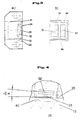
- the construction of the sensor unit results from the schematic representation according to FIG. 3a or 3b.
- the housing 26 which consists of aluminum represented.
- the GMR sensors 28 are arranged in the area of the sensor window 24, the GMR sensors 28 are arranged.
- a frame structure 30 made of plastic which is accommodated in the housing 26, a cuboid permanent magnet 32 is held.
- the permanent magnet is not held directly in the plastic housing, but it is initially embedded in a U-shaped shield.
- stops may be provided in the plastic frame. Due to the necessary fine adjustment, however, the stops offer mainly for positioning the permanent magnet of the reference track.
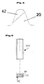
- the U-shaped shield 44 is e.g. shown in Fig. 6.
- the upper sketch shows a plan view and the lower sketch shows a cross section, whereby a permanent magnet is embedded here.
- the shield consists of a soft magnetic material, for example 90MnCrV8.
- the respective edge may be profiled so that a sharp edge 46 is flush with the magnet.
- the edge can also be designed as on the right side of this drawing.
- the front pages can be additionally enclosed.
- the sensor units 28 are arranged such that they generate a signal which is phase-shifted by 90 ° in each case.
- the 90 ° out of phase signals A and B of the sensor units are shown by way of example in FIG.
- a specific transmission behavior ie a specific sensor characteristic with the largest possible Nutzsignalhub, ie large useful signal / Stör elaboratestrade be generated, the magnetic field source, the at least one GMR sensor element and / or the housing at a given distance tilted by a predetermined angle relative to the reference plane of the scale.
- the reference plane is represented by a tooth 38 of an involute toothing. Perpendicular to the tooth or parallel to the tangential plane 40 relative to the tooth 38, the housing 26 is aligned here.
- the sensor element 28 that is to say the GMR sensor, is also aligned parallel to the tangential plane 40 or to the housing 26.
- the permanent magnet 32 which here consists of a cuboid body is tilted at an angle ⁇ relative to the tangential plane 40.
- the period length of the mechanical scale requires a correspondingly adapted scanning length of the sensor element used.
- the signal optimization results in a specific ratio of the distances between the mechanical scale and the sensor element and the sensor element and the permanent magnet, which is likewise to be set.
- the sensor facing surface of the permanent magnet should have at least dimensions of 11 x 5 mm 2 .
- a sufficiently homogeneous magnetic field in the region of the sensor element which has a size of up to approximately 1 ⁇ 0.125 mm 2 , is generated.
- smaller magnets are used, larger differences in the offset voltage of the individual signal tracks can be observed.
- a reference signal R is also shown, which is generated by a parallel sensor unit which is arranged at the level of the zero track 22 when the reference tooth 20 passes.
- the reference tooth 20 can be made of a conventional involute tooth by appropriate profile machining. An involute tooth is processed by milling off the part 42, which is hatched by way of example in FIG. 5, so that a kind of saw tooth profiling stops. By the sawtooth profiling of this reference tooth 20, a bundling of the magnetic field lines is achieved, which ensures the generation of the correct reference signal regardless of the type of sensor used. Even when using field plates instead of GMR sensors, the correspondingly correct reference signal is generated.
- the processing electronics This is conventional. It can be arranged in an external electronic module.
- the processing electronics but arranged in the sensor head.
Landscapes
- Physics & Mathematics (AREA)
- General Physics & Mathematics (AREA)
- Transmission And Conversion Of Sensor Element Output (AREA)
Applications Claiming Priority (1)
| Application Number | Priority Date | Filing Date | Title |
|---|---|---|---|
| DE202005011361U DE202005011361U1 (de) | 2005-07-19 | 2005-07-19 | Magnetfeldempfindlicher Sensor |
Publications (2)
| Publication Number | Publication Date |
|---|---|
| EP1748283A2 true EP1748283A2 (fr) | 2007-01-31 |
| EP1748283A3 EP1748283A3 (fr) | 2011-05-18 |
Family
ID=37239862
Family Applications (1)
| Application Number | Title | Priority Date | Filing Date |
|---|---|---|---|
| EP06015018A Withdrawn EP1748283A3 (fr) | 2005-07-19 | 2006-07-19 | Détecteur sensible au champ magnétique |
Country Status (3)
| Country | Link |
|---|---|
| US (1) | US7423420B2 (fr) |
| EP (1) | EP1748283A3 (fr) |
| DE (1) | DE202005011361U1 (fr) |
Cited By (3)
| Publication number | Priority date | Publication date | Assignee | Title |
|---|---|---|---|---|
| US8240024B2 (en) | 2009-08-25 | 2012-08-14 | International Business Machines Corporation | Methods for fabricating magnetic transducers using post-deposition tilting |
| US8351152B2 (en) | 2009-08-25 | 2013-01-08 | International Business Machines Corporation | Magnetic writer structures formed using post-deposition tilting |
| US8416537B2 (en) | 2009-11-06 | 2013-04-09 | International Business Machines Corporation | Recording head with tilted orientation |
Families Citing this family (12)
| Publication number | Priority date | Publication date | Assignee | Title |
|---|---|---|---|---|
| DE202007014319U1 (de) | 2007-10-12 | 2009-02-26 | Woelke Magnetbandtechnik Gmbh & Co. Kg | Magnetfeldempfindlicher Sensor |
| US9606194B2 (en) | 2008-09-08 | 2017-03-28 | Infineon Technologies Ag | Off-center angle measurement system |
| US8058866B2 (en) * | 2008-09-08 | 2011-11-15 | Infineon Technologies Ag | Off-center angle measurement system |
| US9157970B2 (en) * | 2011-04-05 | 2015-10-13 | Ford Global Technologies, Llc | Method and apparatus for preventing contamination from affecting magnetic field sensors |
| JP5346071B2 (ja) * | 2011-12-02 | 2013-11-20 | ファナック株式会社 | 薄肉の検出面を有する磁気式エンコーダ |
| US9863788B2 (en) | 2014-09-10 | 2018-01-09 | Infineon Technologies Ag | Linear position and rotary position magnetic sensors, systems, and methods |
| US9746346B2 (en) * | 2014-09-10 | 2017-08-29 | Infineon Technologies Ag | Linear position and rotary position magnetic sensors, systems, and methods |
| US20160313139A1 (en) * | 2015-04-27 | 2016-10-27 | United Technologies Corporation | Magnetic encoder assembly |
| JP6316516B2 (ja) * | 2016-03-30 | 2018-04-25 | 三菱電機株式会社 | 磁気センサ装置 |
| CN106602808B (zh) * | 2017-02-13 | 2020-08-25 | 京磁材料科技股份有限公司 | 降低永磁电机齿槽转矩的装配方法 |
| US11614341B2 (en) | 2018-06-14 | 2023-03-28 | Analog Devices International Unlimited Company | Methods and devices for using multi-turn magnetic sensors with extended magnetic windows |
| EP3789735B1 (fr) * | 2019-09-04 | 2021-11-10 | Dr. Johannes Heidenhain GmbH | Dispositif de mesure de position |
Citations (4)
| Publication number | Priority date | Publication date | Assignee | Title |
|---|---|---|---|---|
| DE3240794A1 (de) | 1981-11-06 | 1983-06-01 | Clarion Co., Ltd., Tokyo | Oberflaechenwellenbauelement |
| DE3829390A1 (de) | 1988-08-30 | 1990-03-01 | Rexroth Mannesmann Gmbh | Verfahren und einrichtung zur drehzahlmessung |
| DE3926328A1 (de) | 1989-08-09 | 1991-02-14 | Magnetic Research And Trading | Vorrichtung zum messen von laengen, winkeln und dergleichen |
| DE29614974U1 (de) | 1996-06-11 | 1996-11-28 | Woelke Magnetbandtechnik Gmbh | Steuervorrichtung zur Kompensation von Offset-Anteilen eines periodischen Signals |
Family Cites Families (17)
| Publication number | Priority date | Publication date | Assignee | Title |
|---|---|---|---|---|
| DE3132549A1 (de) * | 1981-08-18 | 1983-03-03 | Robert Bosch Gmbh, 7000 Stuttgart | Vorrichtung zur erfassung der drehzahl von rotierenden teilen |
| DE3214794C2 (de) * | 1982-04-21 | 1984-06-07 | Dr. Johannes Heidenhain Gmbh, 8225 Traunreut | Magnetische Längen- oder Winkelmeßeinrichtung |
| JPS5988612A (ja) * | 1982-11-15 | 1984-05-22 | Toshiba Mach Co Ltd | アブソリユ−ト位置の検知方法および装置 |
| EP0151002B1 (fr) * | 1984-01-25 | 1991-08-28 | Matsushita Electric Industrial Co., Ltd. | Détecteur magnétique |
| US4785242A (en) * | 1986-12-15 | 1988-11-15 | Sundstrand Corporation | Position detecting apparatus using multiple magnetic sensors for determining relative and absolute angular position |
| US5021736A (en) * | 1989-09-19 | 1991-06-04 | Texas Instruments Incorporated | Speed/position sensor calibration method with angular adjustment of a magnetoresistive element |
| US5315244A (en) * | 1989-11-17 | 1994-05-24 | Visi-Trak Corporation | Magnetic sensor with laminated field concentrating flux bar |
| JP2581421Y2 (ja) * | 1991-06-17 | 1998-09-21 | 株式会社村田製作所 | 磁気センサ |
| DE4341890C2 (de) * | 1992-12-09 | 2003-11-06 | Denso Corp | Magnetische Detektionseinrichtung |
| AT407196B (de) * | 1993-11-17 | 2001-01-25 | Amo Automatisierung Messtechni | Positionsmelder für automatisierung |
| US5488294A (en) * | 1995-01-18 | 1996-01-30 | Honeywell Inc. | Magnetic sensor with means for retaining a magnet at a precise calibrated position |
| US5500589A (en) * | 1995-01-18 | 1996-03-19 | Honeywell Inc. | Method for calibrating a sensor by moving a magnet while monitoring an output signal from a magnetically sensitive component |
| JPH09311135A (ja) * | 1996-05-23 | 1997-12-02 | Mitsubishi Electric Corp | 検出装置 |
| DE19623742A1 (de) * | 1996-06-14 | 1997-12-18 | Wittenstein Motion Contr Gmbh | Einrichtung zur Verschiebeweg- und/oder Positionserfassung bei einem Spindeltrieb |
| JPH10239098A (ja) * | 1997-02-26 | 1998-09-11 | Mitsubishi Electric Corp | 磁気検出装置 |
| JP3448209B2 (ja) * | 1998-05-08 | 2003-09-22 | 三菱電機株式会社 | 磁気検出装置 |
| DE10258844A1 (de) * | 2002-12-17 | 2004-03-25 | Robert Bosch Gmbh | Magnetfeldsensorelement und dessen Verwendung |
-
2005
- 2005-07-19 DE DE202005011361U patent/DE202005011361U1/de not_active Expired - Lifetime
-
2006
- 2006-07-19 US US11/490,477 patent/US7423420B2/en not_active Expired - Fee Related
- 2006-07-19 EP EP06015018A patent/EP1748283A3/fr not_active Withdrawn
Patent Citations (4)
| Publication number | Priority date | Publication date | Assignee | Title |
|---|---|---|---|---|
| DE3240794A1 (de) | 1981-11-06 | 1983-06-01 | Clarion Co., Ltd., Tokyo | Oberflaechenwellenbauelement |
| DE3829390A1 (de) | 1988-08-30 | 1990-03-01 | Rexroth Mannesmann Gmbh | Verfahren und einrichtung zur drehzahlmessung |
| DE3926328A1 (de) | 1989-08-09 | 1991-02-14 | Magnetic Research And Trading | Vorrichtung zum messen von laengen, winkeln und dergleichen |
| DE29614974U1 (de) | 1996-06-11 | 1996-11-28 | Woelke Magnetbandtechnik Gmbh | Steuervorrichtung zur Kompensation von Offset-Anteilen eines periodischen Signals |
Cited By (6)
| Publication number | Priority date | Publication date | Assignee | Title |
|---|---|---|---|---|
| US8240024B2 (en) | 2009-08-25 | 2012-08-14 | International Business Machines Corporation | Methods for fabricating magnetic transducers using post-deposition tilting |
| US8351152B2 (en) | 2009-08-25 | 2013-01-08 | International Business Machines Corporation | Magnetic writer structures formed using post-deposition tilting |
| US9230564B2 (en) | 2009-08-25 | 2016-01-05 | Globalfoundries Inc. | Methods for fabricating magnetic transducers using post-deposition tilting |
| US9847099B2 (en) | 2009-08-25 | 2017-12-19 | International Business Machines Corporation | Methods for fabricating magnetic writer structures using post-deposition tilting |
| US10614835B2 (en) | 2009-08-25 | 2020-04-07 | International Business Machines Corporation | Methods for fabricating magnetic writer structures using post-deposition tilting |
| US8416537B2 (en) | 2009-11-06 | 2013-04-09 | International Business Machines Corporation | Recording head with tilted orientation |
Also Published As
| Publication number | Publication date |
|---|---|
| DE202005011361U1 (de) | 2006-11-23 |
| US7423420B2 (en) | 2008-09-09 |
| EP1748283A3 (fr) | 2011-05-18 |
| US20070024280A1 (en) | 2007-02-01 |
Similar Documents
| Publication | Publication Date | Title |
|---|---|---|
| EP0914590B1 (fr) | Systeme pour determiner la position d'arbres en rotation | |
| DE202007014319U1 (de) | Magnetfeldempfindlicher Sensor | |
| EP0628789B1 (fr) | Dispositif de mesure de position | |
| EP0555507B1 (fr) | Capteur de position | |
| EP1748283A2 (fr) | Détecteur sensible au champ magnétique | |
| DE102008059775A1 (de) | Absolut messende Lenkwinkelsensoranordnung | |
| EP0620416B1 (fr) | Système de mesure magnétique | |
| EP0141123A2 (fr) | Dispositif de mesure incrémental photoélectrique | |
| EP2834601B1 (fr) | Procédé et ensemble pour déterminer la position d'un composant | |
| AT392536B (de) | Lineares, inkrementales messsystem | |
| DE102011000486A1 (de) | Absolutes Positionsmesssystem | |
| DE3245357C2 (de) | Inkrementale Meßeinrichtung | |
| DE102010029640B4 (de) | Drehgeberzahnvorrichtung | |
| DE102005021300A1 (de) | Drehgeber | |
| EP2343506B1 (fr) | Dispositif de mesure de longueur | |
| EP1006342B1 (fr) | Procédé de marquage des pistes de mesure | |
| WO1989011079A1 (fr) | Capteur angulaire a position codee | |
| EP1436633A1 (fr) | Appareil de mesure encapsule | |
| DE10123539B4 (de) | Magnetische Längenmessvorrichtung | |
| EP2116814B1 (fr) | Dispositif de mesure destiné à la détermination d'une position et/ou d'une vitesse | |
| EP0729562B1 (fr) | Indicateur de position applique en automatisation | |
| EP1321743A1 (fr) | Système pour mesurer une longueur comprenant une barre de mesure qui se déplace relativement par rapport à des sondes de longueurs mutuellement espacées | |
| DE19800774A1 (de) | Verfahren und magnetische Maßverkörperung zur Generierung eines Referenzsignals sowie Herstellungsverfahren für eine solche magnetische Maßverkörperung | |
| EP0678733B1 (fr) | Système de mesure magnétique de position | |
| EP0973013B1 (fr) | Capteur de déplacement |
Legal Events
| Date | Code | Title | Description |
|---|---|---|---|
| PUAI | Public reference made under article 153(3) epc to a published international application that has entered the european phase |
Free format text: ORIGINAL CODE: 0009012 |
|
| AK | Designated contracting states |
Kind code of ref document: A2 Designated state(s): AT BE BG CH CY CZ DE DK EE ES FI FR GB GR HU IE IS IT LI LT LU LV MC NL PL PT RO SE SI SK TR |
|
| AX | Request for extension of the european patent |
Extension state: AL BA HR MK YU |
|
| RIC1 | Information provided on ipc code assigned before grant |
Ipc: G01D 5/245 20060101ALI20101222BHEP Ipc: G01D 5/16 20060101AFI20061116BHEP |
|
| PUAL | Search report despatched |
Free format text: ORIGINAL CODE: 0009013 |
|
| AK | Designated contracting states |
Kind code of ref document: A3 Designated state(s): AT BE BG CH CY CZ DE DK EE ES FI FR GB GR HU IE IS IT LI LT LU LV MC NL PL PT RO SE SI SK TR |
|
| AX | Request for extension of the european patent |
Extension state: AL BA HR MK RS |
|
| 17P | Request for examination filed |
Effective date: 20111110 |
|
| AKX | Designation fees paid |
Designated state(s): AT BE BG CH CY CZ DE DK EE ES FI FR GB GR HU IE IS IT LI LT LU LV MC NL PL PT RO SE SI SK TR |
|
| STAA | Information on the status of an ep patent application or granted ep patent |
Free format text: STATUS: THE APPLICATION IS DEEMED TO BE WITHDRAWN |
|
| 18D | Application deemed to be withdrawn |
Effective date: 20150203 |