EP1748363A1 - Architecture de bus et procédé destiné à l'échange de données - Google Patents
Architecture de bus et procédé destiné à l'échange de données Download PDFInfo
- Publication number
- EP1748363A1 EP1748363A1 EP06013898A EP06013898A EP1748363A1 EP 1748363 A1 EP1748363 A1 EP 1748363A1 EP 06013898 A EP06013898 A EP 06013898A EP 06013898 A EP06013898 A EP 06013898A EP 1748363 A1 EP1748363 A1 EP 1748363A1
- Authority
- EP
- European Patent Office
- Prior art keywords
- bus
- data
- data line
- unit
- central unit
- Prior art date
- Legal status (The legal status is an assumption and is not a legal conclusion. Google has not performed a legal analysis and makes no representation as to the accuracy of the status listed.)
- Granted
Links
- 238000000034 method Methods 0.000 title claims abstract description 10
- 230000005540 biological transmission Effects 0.000 claims abstract description 23
- 238000012544 monitoring process Methods 0.000 claims abstract description 23
- 230000000694 effects Effects 0.000 claims abstract description 11
- 230000015654 memory Effects 0.000 claims description 6
- 230000009849 deactivation Effects 0.000 claims description 3
- 230000000903 blocking effect Effects 0.000 claims 1
- 230000006870 function Effects 0.000 description 7
- 238000004891 communication Methods 0.000 description 2
- 238000013461 design Methods 0.000 description 2
- 230000004807 localization Effects 0.000 description 2
- 208000027765 speech disease Diseases 0.000 description 2
- 230000006399 behavior Effects 0.000 description 1
- 238000005352 clarification Methods 0.000 description 1
- 238000010276 construction Methods 0.000 description 1
- 230000008094 contradictory effect Effects 0.000 description 1
- 230000002950 deficient Effects 0.000 description 1
- 230000001419 dependent effect Effects 0.000 description 1
- 230000009977 dual effect Effects 0.000 description 1
- 238000005516 engineering process Methods 0.000 description 1
- 238000012545 processing Methods 0.000 description 1
- 230000002123 temporal effect Effects 0.000 description 1
Images


Classifications
-
- H—ELECTRICITY
- H04—ELECTRIC COMMUNICATION TECHNIQUE
- H04L—TRANSMISSION OF DIGITAL INFORMATION, e.g. TELEGRAPHIC COMMUNICATION
- H04L12/00—Data switching networks
- H04L12/28—Data switching networks characterised by path configuration, e.g. LAN [Local Area Networks] or WAN [Wide Area Networks]
- H04L12/40—Bus networks
- H04L12/403—Bus networks with centralised control, e.g. polling
-
- H—ELECTRICITY
- H04—ELECTRIC COMMUNICATION TECHNIQUE
- H04L—TRANSMISSION OF DIGITAL INFORMATION, e.g. TELEGRAPHIC COMMUNICATION
- H04L12/00—Data switching networks
- H04L12/28—Data switching networks characterised by path configuration, e.g. LAN [Local Area Networks] or WAN [Wide Area Networks]
- H04L12/40—Bus networks
- H04L12/40169—Flexible bus arrangements
- H04L12/40176—Flexible bus arrangements involving redundancy
- H04L12/40182—Flexible bus arrangements involving redundancy by using a plurality of communication lines
-
- H—ELECTRICITY
- H04—ELECTRIC COMMUNICATION TECHNIQUE
- H04L—TRANSMISSION OF DIGITAL INFORMATION, e.g. TELEGRAPHIC COMMUNICATION
- H04L12/00—Data switching networks
- H04L12/28—Data switching networks characterised by path configuration, e.g. LAN [Local Area Networks] or WAN [Wide Area Networks]
- H04L12/42—Loop networks
- H04L12/423—Loop networks with centralised control, e.g. polling
-
- H—ELECTRICITY
- H04—ELECTRIC COMMUNICATION TECHNIQUE
- H04L—TRANSMISSION OF DIGITAL INFORMATION, e.g. TELEGRAPHIC COMMUNICATION
- H04L12/00—Data switching networks
- H04L12/28—Data switching networks characterised by path configuration, e.g. LAN [Local Area Networks] or WAN [Wide Area Networks]
- H04L12/40—Bus networks
- H04L2012/40208—Bus networks characterized by the use of a particular bus standard
- H04L2012/40215—Controller Area Network CAN
-
- H—ELECTRICITY
- H04—ELECTRIC COMMUNICATION TECHNIQUE
- H04L—TRANSMISSION OF DIGITAL INFORMATION, e.g. TELEGRAPHIC COMMUNICATION
- H04L12/00—Data switching networks
- H04L12/28—Data switching networks characterised by path configuration, e.g. LAN [Local Area Networks] or WAN [Wide Area Networks]
- H04L12/40—Bus networks
- H04L2012/40267—Bus for use in transportation systems
- H04L2012/4028—Bus for use in transportation systems the transportation system being an aircraft
Definitions
- the invention relates to a bus architecture, in particular for an aircraft, with a central unit, with a data line and with a number of bus subscribers, wherein the central unit and the bus subscribers are each connected to the data line via a bus interface.
- the invention further relates to a method for data exchange with such a bus architecture.
- Such a bus architecture serves to exchange data between the central unit and the bus users. In this way, both data can be accessed via the bus subscribers and data can be forwarded to the bus subscribers.
- a bus architecture is primarily designed to provide data exchange with the lowest possible error rate. This can be achieved, for example, via the configuration of the data line as such or via the type of coding of the data to be exchanged.
- bus control units are responsible for converting the electronic data originating from a hardware or a software into the data provided for the data exchange by means of the bus architecture in a predetermined protocol.
- the central unit and the bus subscribers are further connected by a bus interface to the data line, wherein the physical interface of the bus interface essentially brings about a leveling of the data supplied by the bus control unit into the data line.
- the individual bus users can also be switched on or off.
- Bus subscribers can be sensors, controllers, actuators, data memories or general hardware or software components.
- the central unit has the task of centrally monitoring, controlling or managing the individual bus subscribers Retrieve data from the bus subscribers.
- the central unit is also referred to as a "master”, while the other bus subscribers connected to the central unit via the data line are also referred to as "slaves”.
- the first object is achieved according to the invention for a bus architecture of the type mentioned above in that the data line is formed as a ring in which both ends of the data line are connected to the central unit, that the central unit has switchable transceiver units between transmitting and receiving operation, wherein a transceiver unit is connected in each case via a bus interface with one end of the data line, that the central unit is prepared for clocked transmission of the data provided for the bus subscriber, the bus subscribers are connected one behind the other to the data line, and that the bus subscribers each with the associated bus interface associated monitoring unit, which is designed to activate only after receipt of a synchronization message transmission activity of the interface and otherwise block.
- the invention proceeds in a first step from the consideration that in the case of the severing of the data line that in the separated from the central unit Part of the data line connected bus subscriber irrevocably withdrawn from the data exchange.
- this can be prevented if a data line to which the bus subscribers are connected one behind the other does not end as usual in a termination, but the free end is reconnected to the central unit.
- an annular shape of the data line is achieved.
- the invention is based on the consideration that an error can be easily located in such a data line designed as a ring if the central unit is prepared for the clocked transmission of the data provided for the bus subscribers.
- the central unit transmits the data or data packets provided for the bus subscribers connected one behind the other to the data line in chronological succession in accordance with the timing. Each of these data packets is available to the connected bus subscriber at a precisely predetermined and, in particular, predictable time.
- each bus subscriber is assigned a monitoring unit which only activates a transmission activity of the interface after receiving a synchronization message and otherwise blocks it
- the bus users also send their data to the data line only at a predictable time.
- the data sent from one bus subscriber to the data line is available at a precisely predetermined time for the central unit.
- the transmission activity of the interface is activated only after receipt of a synchronization message, it is ensured that a defective bus user does not send senseless data to the data line, which means that the entire communication can fail in a conventional bus architecture.
- the returning data of the bus subscribers are each assigned to a specific bus subscriber. If no data is available for the central unit for a certain period of time, it may become concluded that a specific bus subscriber has failed. If the central unit detects unexpected data within a certain period of time, it is possible to conclude that a specific bus user has made a mistake and this bus user is deactivated, for example. In other words, faults within the bus architecture can be localized in this way.
- the bus users each comprise two transceiver units, wherein the first transceiver unit is connected to the processor, and wherein the second transceiver unit is configured as a hardware component.
- the hardware module can provide the same output data as the transceiver unit connected to the processor by means of an electronic circuit when receiving data.
- the first transceiver unit for monitoring output signals is connected to the second transceiver unit, and has a signal output connected to the monitoring unit or the bus interface for outputting a control signal. If the transceiver unit connected to the processor detects an atypical behavior of the hardware module, then the bus interface is blocked via the signal output by means of the monitoring unit or directly with regard to its transmission activity.
- the bus users comprise a memory module which is prepared for storing the data to be queried by means of the central unit during the deactivation of the transmission activity of the assigned interface. This relieves any processor. The preparation of the data during the transmission activity by the processor is eliminated. Instead, the data stored in the memory device during the deactivation phase is retrieved and sent to the data line.
- the data line and / or the central unit comprises an interface to other bus systems, this enables communication or data exchange between different bus systems.
- the information received from the bus users of the bus architecture described information can be fed, for example in a higher-level bus system, which serves to monitor and display functions of an aircraft.
- the bus subscribers are local electronic door controls of an aircraft.
- the bus subscribers are local electronic door controls of an aircraft.
- Airbus A380 passenger doors and cargo doors are no longer controlled mechanically but electronically.
- Each door has a local door control that detects and controls each door position via sensors and actuators.
- the monitoring of the door closing function for the safety of the aircraft is of paramount importance.
- the local door controllers are integrated as bus subscribers in the bus architecture described here.
- the data line and the bus interfaces are designed to conform to CAN bus.
- the physical design of a CAN bus as well as the coding of the data to be exchanged or the associated protocol are internationally standardized in ISO 11898. Such a configuration makes use of proven technology with regard to the bus control units and the bus interfaces.
- the second-mentioned object is achieved according to the invention for a method for exchanging data between a central unit and a number of bus subscribers in a bus architecture of the type mentioned above, in that one transceiver unit of the central unit operates as a transmitter, while the other transceiver unit is connected as a receiver , wherein the two transceiver units exchange their task after a predetermined period of time that the transmitter-receiver unit connected as transmitter transmits successively the data intended for the respective bus subscriber with an information signal into the data line with a predetermined clock time that the receiver is switched in each case Transceiver monitors the data exchange in the data line that each information signal is provided with a synchronization message and addressing message, and that the bus subscribers only after receiving the associated synchronization signal for ei Send a predetermined period of time and otherwise only receive while sending is blocked.
- the circulating in the data line individual data packets can be observed from two directions and accurately localized errors accordingly. While one sends a transceiver, the other transceiver observes the circulating data packets. After a certain time will be switched.
- the cycle time essentially corresponds to the cycle time of a signal in the data line divided by the number of bus subscribers.
- the cycle time is used for data exchange with the respective bus subscriber. After one revolution in the annular data line, data is exchanged with each bus subscriber.
- the transceiver units in the central unit after the round trip time swap their task and send the bus participants after receiving the synchronization message for the duration of the clock time.
- the monitoring direction with regard to data line is reversed after a complete data exchange with all bus users. The error location is maximized in this way. For each bus user, the maximum possible time frame for the data exchange is provided.
- FIG. 1 schematically shows a bus architecture 1 comprising a central unit 3, a data line 5 and bus subscribers 6.
- the central unit 3 operates as a "master” while the individual bus users 6 function as “slaves”.
- the central unit 3 has two bus interfaces 7, which are connected to the transceiver units 8 and 9 via a respective bus control unit 10.
- the bus participants 6 are also connected in series via a non-drawn bus interface to the data line 5.
- the data line 5 is ring-shaped, wherein a first end 12 of the data line 5 is connected via the associated bus interface 7 with the transceiver unit 8 and a second end 13 of the data line 5 via the corresponding bus interface 7 with the further transceiver unit 9.
- the two transceiver units 8 and 9 work alternately as transmitter and receiver.
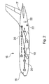
- FIG. 2 shows a side view of a modern passenger plane 15, from which the cockpit 16, the tail fin 17 and the engines 18 can be clearly seen.
- Such an aircraft 15 has on both sides a number of passenger doors 20 and cargo doors 22. Both the passenger doors 20 and the cargo doors 22 are provided with local door controls, which are integrated as bus subscribers 6 in the bus architecture 1 according to FIG. 1.
- the central unit 3 accordingly has a total of four transceiver units 8, 9, 31 and 32, respectively.
- the transceiver units 8 and 9 are used for transmitting or receiving data in and out of the right-hand data line 25.
- the transceiver units 31 and 32 are assigned corresponding to the left-hand data line 26.
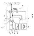
- Fig. 4 the structure of a bus participant 6 is shown schematically.
- the bus subscriber 6 has a bus interface 7 for connection to the data line 5 for level adjustment.
- two transceiver units 40 and 41 are connected to encode or decode the data to be exchanged.
- a bus control unit 10 is interposed in each case.
- the transceiver unit 40 has a memory module 44 and a processor 45.
- the transceiver 41 comprises a hardware module 46. Via the common transmission line 47, it is possible for the transceiver unit 40 to monitor the transmission data of the transceiver unit 41.
- the transceiver unit 41 shares the associated bus control unit 10 with a monitoring unit 43, which is connected to the bus interface 7.
- the monitoring unit 43 activates the transmission activity of the bus interface 7 only when a correspondingly assigned synchronization message is received via the data line 5. Otherwise, the bus interface 7 is activated only for the reception.
- a control signal is generated, which is connected via the signal output 50 and a logic module 52 in the form of an AND operation of the connection between the monitoring unit 43 and the Bus interface 7 is supplied. In this way, it is achieved that the bus interface 7 is activated for transmission only when the transceiver unit 40 is released.
- a corresponding data packet is available for the illustrated bus subscriber 6, which receives a synchronization message and an addressing message.
- the monitoring unit 43 detects the synchronization message and the addressing message and recognizes that the following data packet is addressed to the own bus subscriber 6.
- the bus interface 7 is then activated for transmission.
- the transceiver unit 40 and the transceiver unit 41 respond to the transmitted data and send their output data via the bus interface 7 in the data line 5.
- the transceiver unit 40 sends the written by means of the processor 44 in the memory module 45 during the pass-passive time Dates.
- the processor 44 is designed, for example, as a local door control, which processes data from numerous actuators and sensors and makes them available via the memory module 45. This allows a query of the important for the safety of the aircraft door status.
- Fig. 5 shows the time course of the data exchange within the described bus architecture. Shown is the data exchange for a cycle time 55 in the annular data line. With a cycle time 56, data packets 57 and 58 provided one after the other in the ring-shaped data line for the respective bus users are transmitted. The data packets 57 are provided for on the right side of an aircraft local door controls, while the data packets 58 are assigned to the arranged on the left side of an aircraft left door controls.
- the circulation time 55 and the individual data packets 58 are again shown as a detail from FIG.
- the cycle time 56 is shown in addition spread.
- the data packet 58 located in the data line comprises a preceding information signal 59 generated by the central unit, which contains a synchronization message 60 and an addressing message 61.
- the monitoring unit 43 shown in FIG. 4 transmits the bus interface assigned to the bus subscriber in a send-active manner, so that the corresponding local door controller sends its transmission data 63 into the data line.
- the Send function of the corresponding interface disabled.
- the specific local door controller or specific bus master sends no data to the data line. These periods are available to the other bus subscribers.
Landscapes
- Engineering & Computer Science (AREA)
- Computer Networks & Wireless Communication (AREA)
- Signal Processing (AREA)
- Small-Scale Networks (AREA)
Applications Claiming Priority (1)
| Application Number | Priority Date | Filing Date | Title |
|---|---|---|---|
| DE102005035611.7A DE102005035611C5 (de) | 2005-07-29 | 2005-07-29 | Busarchitektur sowie Verfahren zum Datenaustausch |
Publications (2)
| Publication Number | Publication Date |
|---|---|
| EP1748363A1 true EP1748363A1 (fr) | 2007-01-31 |
| EP1748363B1 EP1748363B1 (fr) | 2008-12-31 |
Family
ID=37308756
Family Applications (1)
| Application Number | Title | Priority Date | Filing Date |
|---|---|---|---|
| EP06013898A Ceased EP1748363B1 (fr) | 2005-07-29 | 2006-07-05 | Architecture de bus et procédé destiné à l'échange de données |
Country Status (4)
| Country | Link |
|---|---|
| US (1) | US7738477B2 (fr) |
| EP (1) | EP1748363B1 (fr) |
| CA (1) | CA2547502C (fr) |
| DE (2) | DE102005035611C5 (fr) |
Families Citing this family (6)
| Publication number | Priority date | Publication date | Assignee | Title |
|---|---|---|---|---|
| JP2006525725A (ja) * | 2003-05-06 | 2006-11-09 | コーニンクレッカ フィリップス エレクトロニクス エヌ ヴィ | Tdmaバスにおける異なるサイクルでのタイムスロット共有 |
| DE102005037723B4 (de) * | 2005-08-10 | 2014-03-13 | Continental Teves Ag & Co. Ohg | Steuerungseinheit für Verbundbetrieb |
| EP2077281A1 (fr) | 2008-01-02 | 2009-07-08 | Bergen Teknologioverforing AS | Anticorps anti-CD20 ou fragments correspondants pour le traitement de syndrome de fatigue chronique |
| DE202008009211U1 (de) * | 2008-07-09 | 2008-09-25 | Robert Bosch Gmbh | Vorrichtung zur Erkennung von Unterbrechungen bei einem Ringbus |
| US9563580B2 (en) * | 2013-07-25 | 2017-02-07 | North Flight Data Systems, LLC | System, methodology, and process for wireless transmission of sensor data onboard an aircraft to a portable electronic device |
| US11099936B2 (en) * | 2018-09-11 | 2021-08-24 | Embraer S.A. | Aircraft integrated multi system electronic architecture |
Citations (3)
| Publication number | Priority date | Publication date | Assignee | Title |
|---|---|---|---|---|
| DE3919144C1 (en) * | 1989-06-12 | 1990-12-06 | Telenorma Telefonbau Und Normalzeit Gmbh, 6000 Frankfurt, De | Digital transmission procedure for telecommunications system - switching station in series on ring-structure bus allowing async. exchange of data packets of various length |
| US5793946A (en) * | 1996-03-12 | 1998-08-11 | Varis Corporation | Run-time diagnostic system |
| US20030039243A1 (en) * | 2001-06-26 | 2003-02-27 | Parker Jon A. | Technique for creating a fault-tolerant daisy-chained serial bus |
Family Cites Families (15)
| Publication number | Priority date | Publication date | Assignee | Title |
|---|---|---|---|---|
| DE3424866C2 (de) * | 1984-07-06 | 1986-04-30 | Messerschmitt-Bölkow-Blohm GmbH, 8012 Ottobrunn | Verfahren und Anordnung zur Übertragung von Daten, insbesondere in einem Flugzeug |
| US4633461A (en) * | 1985-07-08 | 1986-12-30 | At&T Information Systems Inc. | Switching control for multiple stage time division switch |
| US4787082A (en) * | 1986-07-24 | 1988-11-22 | American Telephone And Telegraph Company, At&T Bell Laboratories | Data flow control arrangement for local area network |
| DE3628299A1 (de) * | 1986-08-21 | 1988-02-25 | Licentia Gmbh | Verfahren und anordnung zum signaltechnisch sicheren uebertragen von seriellen daten zwischen vorzugsweise zweikanaligen sicheren rechnern unter verwendung eines doppelringbussystems |
| US4829297A (en) * | 1987-05-08 | 1989-05-09 | Allen-Bradley Company, Inc. | Communication network polling technique |
| US5434861A (en) * | 1989-02-02 | 1995-07-18 | Pritty; David | Deterministic timed bus access method |
| US5404536A (en) * | 1992-09-15 | 1995-04-04 | Digital Equipment Corp. | Scheduling mechanism for network adapter to minimize latency and guarantee background processing time |
| EP0663637A1 (fr) * | 1994-01-12 | 1995-07-19 | T.R.T. Telecommunications Radioelectriques Et Telephoniques | Support de communication pour équipement électronique à plusieurs processeurs répartis |
| US5809220A (en) * | 1995-07-20 | 1998-09-15 | Raytheon Company | Fault tolerant distributed control system |
| DE19723274C2 (de) | 1997-06-04 | 2000-05-25 | Harting Kgaa | Datenübertragungssystem |
| DE19922171B4 (de) * | 1999-05-12 | 2009-08-27 | Infineon Technologies Ag | Kommunikationssystem mit einem Kommunikationsbus |
| GB9919240D0 (en) * | 1999-08-13 | 1999-10-20 | Wynstruments Ltd | Marine ancillary component control and monitoring systems and methods of controlling and monitoring ancillary components |
| DE19939996B4 (de) * | 1999-08-24 | 2020-02-27 | Robert Bosch Gmbh | Schliessanlage |
| WO2003022647A1 (fr) * | 2001-09-11 | 2003-03-20 | Kevin Orton | Systeme et procede de securite de vol d'aeronefs |
| DE10153846B4 (de) * | 2001-11-02 | 2004-11-25 | Daimlerchrysler Ag | Zünd- oder Einspritzmodul und zugehörendes Initialisierungsverfahren |
-
2005
- 2005-07-29 DE DE102005035611.7A patent/DE102005035611C5/de not_active Expired - Fee Related
-
2006
- 2006-05-23 CA CA2547502A patent/CA2547502C/fr active Active
- 2006-07-05 DE DE502006002475T patent/DE502006002475D1/de active Active
- 2006-07-05 EP EP06013898A patent/EP1748363B1/fr not_active Ceased
- 2006-07-13 US US11/485,673 patent/US7738477B2/en active Active
Patent Citations (3)
| Publication number | Priority date | Publication date | Assignee | Title |
|---|---|---|---|---|
| DE3919144C1 (en) * | 1989-06-12 | 1990-12-06 | Telenorma Telefonbau Und Normalzeit Gmbh, 6000 Frankfurt, De | Digital transmission procedure for telecommunications system - switching station in series on ring-structure bus allowing async. exchange of data packets of various length |
| US5793946A (en) * | 1996-03-12 | 1998-08-11 | Varis Corporation | Run-time diagnostic system |
| US20030039243A1 (en) * | 2001-06-26 | 2003-02-27 | Parker Jon A. | Technique for creating a fault-tolerant daisy-chained serial bus |
Also Published As
| Publication number | Publication date |
|---|---|
| DE102005035611C5 (de) | 2014-05-15 |
| CA2547502C (fr) | 2014-10-14 |
| US20070025375A1 (en) | 2007-02-01 |
| DE102005035611A1 (de) | 2007-02-08 |
| CA2547502A1 (fr) | 2007-01-29 |
| DE502006002475D1 (de) | 2009-02-12 |
| EP1748363B1 (fr) | 2008-12-31 |
| US7738477B2 (en) | 2010-06-15 |
| DE102005035611B4 (de) | 2007-07-12 |
Similar Documents
| Publication | Publication Date | Title |
|---|---|---|
| DE3586486T2 (de) | Interface-vorrichtung zwischen mindestens einem kanal und mindestens einem bus. | |
| EP1566029B1 (fr) | Unite de passerelle permettant de connecter des sous-reseaux, notamment dans des vehicules | |
| DE3586487T2 (de) | Kohaerentes interface mit zurueckgeschleiften sende- und empfangsspeichern. | |
| DE10353950C5 (de) | Steuerungssystem | |
| EP0698980B1 (fr) | Système bus sériel | |
| DE19934514C5 (de) | Verfahren zum Konfigurieren eines an einen Feldbus angeschlossenen Busteilnehmers | |
| EP2795848B1 (fr) | Station participante à un système de bus et procédé de transmission de messages entre des stations participantes à un système de bus | |
| DE19922171B4 (de) | Kommunikationssystem mit einem Kommunikationsbus | |
| EP1509005B1 (fr) | Méthode et appareil pour la transmission de données par diffusion dans un réseau bus | |
| DE69610874T2 (de) | Vorrichtung zur Datenübertragung zwischen einer Mehrzahl von Funktionsmodulen in einer lokalen Buseinheit und einem externen ARINC-629-Bus | |
| EP1410577B1 (fr) | Elements reseau destines a un reseau optique ayant une fonction de securite, en particulier a un reseau optique a topologie annulaire | |
| WO2020120550A1 (fr) | Unité de détection de recouvrement pour un poste d'abonné d'un système de bus série et procédé de communication dans un système de bus série | |
| EP1748363B1 (fr) | Architecture de bus et procédé destiné à l'échange de données | |
| DE102009015944B4 (de) | Zeitteilermehrfahrzugriffs-Kommunikationsnetzwerksystem | |
| DE102014210505A1 (de) | Übertragungseinheit mit Prüffunktion | |
| EP1784737A1 (fr) | Module de communication comprenant un element d'interface de communication et element d'interface de communication | |
| EP1227406B1 (fr) | Dispositif d'émission et de réception avec des moyens de gestion d'erreur | |
| DE102015220964B4 (de) | Elektronische Steuerungsvorrichtung | |
| EP1881413B1 (fr) | Système de communication pour l'utilisation flexible dans différents cas d'utilisation de la technique d'automatisation | |
| DE102006004191B4 (de) | Deterministisches Kommunikations-System | |
| EP3104558B1 (fr) | Interface réseau, réseau et procédé de transmission de données dans le réseau | |
| EP4035314B1 (fr) | Dispositif esclave, système de bus et procédés | |
| DE10216920A1 (de) | Verfahren und Vorrichtung zur Überprüfung einer Überwachungsfunktion eines Bussystems und Bussystem | |
| EP1675310B1 (fr) | Procédé de communication des données et système bus des données pour automobile | |
| EP2822230B1 (fr) | Transmission de données via une mémoire d'un dispositif de communication |
Legal Events
| Date | Code | Title | Description |
|---|---|---|---|
| PUAI | Public reference made under article 153(3) epc to a published international application that has entered the european phase |
Free format text: ORIGINAL CODE: 0009012 |
|
| 17P | Request for examination filed |
Effective date: 20061128 |
|
| AK | Designated contracting states |
Kind code of ref document: A1 Designated state(s): AT BE BG CH CY CZ DE DK EE ES FI FR GB GR HU IE IS IT LI LT LU LV MC NL PL PT RO SE SI SK TR |
|
| AX | Request for extension of the european patent |
Extension state: AL BA HR MK YU |
|
| AKX | Designation fees paid |
Designated state(s): DE FR GB IT |
|
| GRAP | Despatch of communication of intention to grant a patent |
Free format text: ORIGINAL CODE: EPIDOSNIGR1 |
|
| GRAS | Grant fee paid |
Free format text: ORIGINAL CODE: EPIDOSNIGR3 |
|
| GRAA | (expected) grant |
Free format text: ORIGINAL CODE: 0009210 |
|
| AK | Designated contracting states |
Kind code of ref document: B1 Designated state(s): DE FR GB IT |
|
| REG | Reference to a national code |
Ref country code: GB Ref legal event code: FG4D Free format text: NOT ENGLISH |
|
| REF | Corresponds to: |
Ref document number: 502006002475 Country of ref document: DE Date of ref document: 20090212 Kind code of ref document: P |
|
| PLBE | No opposition filed within time limit |
Free format text: ORIGINAL CODE: 0009261 |
|
| STAA | Information on the status of an ep patent application or granted ep patent |
Free format text: STATUS: NO OPPOSITION FILED WITHIN TIME LIMIT |
|
| 26N | No opposition filed |
Effective date: 20091001 |
|
| REG | Reference to a national code |
Ref country code: FR Ref legal event code: PLFP Year of fee payment: 11 |
|
| PGFP | Annual fee paid to national office [announced via postgrant information from national office to epo] |
Ref country code: IT Payment date: 20160725 Year of fee payment: 11 Ref country code: GB Payment date: 20160721 Year of fee payment: 11 |
|
| REG | Reference to a national code |
Ref country code: FR Ref legal event code: PLFP Year of fee payment: 12 |
|
| GBPC | Gb: european patent ceased through non-payment of renewal fee |
Effective date: 20170705 |
|
| PG25 | Lapsed in a contracting state [announced via postgrant information from national office to epo] |
Ref country code: GB Free format text: LAPSE BECAUSE OF NON-PAYMENT OF DUE FEES Effective date: 20170705 |
|
| REG | Reference to a national code |
Ref country code: FR Ref legal event code: PLFP Year of fee payment: 13 |
|
| PG25 | Lapsed in a contracting state [announced via postgrant information from national office to epo] |
Ref country code: IT Free format text: LAPSE BECAUSE OF NON-PAYMENT OF DUE FEES Effective date: 20170705 |
|
| PGFP | Annual fee paid to national office [announced via postgrant information from national office to epo] |
Ref country code: FR Payment date: 20230725 Year of fee payment: 18 Ref country code: DE Payment date: 20230907 Year of fee payment: 18 |
|
| REG | Reference to a national code |
Ref country code: DE Ref legal event code: R119 Ref document number: 502006002475 Country of ref document: DE |
|
| PG25 | Lapsed in a contracting state [announced via postgrant information from national office to epo] |
Ref country code: DE Free format text: LAPSE BECAUSE OF NON-PAYMENT OF DUE FEES Effective date: 20250201 |
|
| PG25 | Lapsed in a contracting state [announced via postgrant information from national office to epo] |
Ref country code: FR Free format text: LAPSE BECAUSE OF NON-PAYMENT OF DUE FEES Effective date: 20240731 |