EP1748449A1 - Isolateur avec une capacité augmentée d'isolation - Google Patents
Isolateur avec une capacité augmentée d'isolation Download PDFInfo
- Publication number
- EP1748449A1 EP1748449A1 EP20050016096 EP05016096A EP1748449A1 EP 1748449 A1 EP1748449 A1 EP 1748449A1 EP 20050016096 EP20050016096 EP 20050016096 EP 05016096 A EP05016096 A EP 05016096A EP 1748449 A1 EP1748449 A1 EP 1748449A1
- Authority
- EP
- European Patent Office
- Prior art keywords
- insulator
- hydrophobic
- surface coating
- hydrophobic surface
- isolator
- Prior art date
- Legal status (The legal status is an assumption and is not a legal conclusion. Google has not performed a legal analysis and makes no representation as to the accuracy of the status listed.)
- Withdrawn
Links
- 239000012212 insulator Substances 0.000 title claims abstract description 46
- 238000009413 insulation Methods 0.000 title claims description 21
- 239000000463 material Substances 0.000 claims abstract description 25
- 238000000576 coating method Methods 0.000 claims abstract description 19
- 239000011248 coating agent Substances 0.000 claims abstract description 18
- 230000002209 hydrophobic effect Effects 0.000 claims abstract description 17
- 230000005661 hydrophobic surface Effects 0.000 claims abstract description 17
- 229920006362 Teflon® Polymers 0.000 claims abstract description 7
- 229920001343 polytetrafluoroethylene Polymers 0.000 claims abstract description 7
- 239000004810 polytetrafluoroethylene Substances 0.000 claims abstract description 7
- 229920002313 fluoropolymer Polymers 0.000 claims abstract description 6
- 239000004811 fluoropolymer Substances 0.000 claims abstract description 6
- -1 polytetrafluoroethylene Polymers 0.000 claims abstract description 6
- 239000004809 Teflon Substances 0.000 claims abstract description 5
- 150000001343 alkyl silanes Chemical class 0.000 claims abstract description 4
- 230000004048 modification Effects 0.000 claims abstract description 4
- 238000012986 modification Methods 0.000 claims abstract description 4
- 239000007789 gas Substances 0.000 claims description 3
- 239000002904 solvent Substances 0.000 abstract description 6
- 229920001296 polysiloxane Polymers 0.000 abstract description 2
- 239000011810 insulating material Substances 0.000 abstract 1
- 239000000446 fuel Substances 0.000 description 16
- XLYOFNOQVPJJNP-UHFFFAOYSA-N water Substances O XLYOFNOQVPJJNP-UHFFFAOYSA-N 0.000 description 13
- 238000001035 drying Methods 0.000 description 6
- 238000001816 cooling Methods 0.000 description 4
- 238000009833 condensation Methods 0.000 description 3
- 230000005494 condensation Effects 0.000 description 3
- 239000004020 conductor Substances 0.000 description 3
- 239000010410 layer Substances 0.000 description 3
- 239000004033 plastic Substances 0.000 description 3
- 229920003023 plastic Polymers 0.000 description 3
- 230000001680 brushing effect Effects 0.000 description 2
- 239000000919 ceramic Substances 0.000 description 2
- 150000001875 compounds Chemical class 0.000 description 2
- 230000001376 precipitating effect Effects 0.000 description 2
- 239000000725 suspension Substances 0.000 description 2
- 238000009736 wetting Methods 0.000 description 2
- YSYRISKCBOPJRG-UHFFFAOYSA-N 4,5-difluoro-2,2-bis(trifluoromethyl)-1,3-dioxole Chemical compound FC1=C(F)OC(C(F)(F)F)(C(F)(F)F)O1 YSYRISKCBOPJRG-UHFFFAOYSA-N 0.000 description 1
- UFHFLCQGNIYNRP-UHFFFAOYSA-N Hydrogen Chemical compound [H][H] UFHFLCQGNIYNRP-UHFFFAOYSA-N 0.000 description 1
- QVGXLLKOCUKJST-UHFFFAOYSA-N atomic oxygen Chemical compound [O] QVGXLLKOCUKJST-UHFFFAOYSA-N 0.000 description 1
- 239000003990 capacitor Substances 0.000 description 1
- 239000000969 carrier Substances 0.000 description 1
- 229910010293 ceramic material Inorganic materials 0.000 description 1
- 229920001577 copolymer Polymers 0.000 description 1
- 230000007797 corrosion Effects 0.000 description 1
- 238000005260 corrosion Methods 0.000 description 1
- 230000001419 dependent effect Effects 0.000 description 1
- 238000007598 dipping method Methods 0.000 description 1
- 230000000694 effects Effects 0.000 description 1
- 230000007613 environmental effect Effects 0.000 description 1
- 238000001704 evaporation Methods 0.000 description 1
- 230000008020 evaporation Effects 0.000 description 1
- 239000001257 hydrogen Substances 0.000 description 1
- 229910052739 hydrogen Inorganic materials 0.000 description 1
- 238000002955 isolation Methods 0.000 description 1
- 238000004519 manufacturing process Methods 0.000 description 1
- 238000000034 method Methods 0.000 description 1
- 239000001301 oxygen Substances 0.000 description 1
- 229910052760 oxygen Inorganic materials 0.000 description 1
- 239000002244 precipitate Substances 0.000 description 1
- 239000000047 product Substances 0.000 description 1
- 239000005871 repellent Substances 0.000 description 1
- 238000005507 spraying Methods 0.000 description 1
- 239000002344 surface layer Substances 0.000 description 1
- 238000004381 surface treatment Methods 0.000 description 1
- BFKJFAAPBSQJPD-UHFFFAOYSA-N tetrafluoroethene Chemical group FC(F)=C(F)F BFKJFAAPBSQJPD-UHFFFAOYSA-N 0.000 description 1
Images
Classifications
-
- H—ELECTRICITY
- H01—ELECTRIC ELEMENTS
- H01B—CABLES; CONDUCTORS; INSULATORS; SELECTION OF MATERIALS FOR THEIR CONDUCTIVE, INSULATING OR DIELECTRIC PROPERTIES
- H01B17/00—Insulators or insulating bodies characterised by their form
- H01B17/50—Insulators or insulating bodies characterised by their form with surfaces specially treated for preserving insulating properties, e.g. for protection against moisture, dirt, or the like
-
- H—ELECTRICITY
- H01—ELECTRIC ELEMENTS
- H01B—CABLES; CONDUCTORS; INSULATORS; SELECTION OF MATERIALS FOR THEIR CONDUCTIVE, INSULATING OR DIELECTRIC PROPERTIES
- H01B3/00—Insulators or insulating bodies characterised by the insulating materials; Selection of materials for their insulating or dielectric properties
- H01B3/18—Insulators or insulating bodies characterised by the insulating materials; Selection of materials for their insulating or dielectric properties mainly consisting of organic substances
- H01B3/30—Insulators or insulating bodies characterised by the insulating materials; Selection of materials for their insulating or dielectric properties mainly consisting of organic substances plastics; resins; waxes
- H01B3/44—Insulators or insulating bodies characterised by the insulating materials; Selection of materials for their insulating or dielectric properties mainly consisting of organic substances plastics; resins; waxes vinyl resins; acrylic resins
- H01B3/443—Insulators or insulating bodies characterised by the insulating materials; Selection of materials for their insulating or dielectric properties mainly consisting of organic substances plastics; resins; waxes vinyl resins; acrylic resins from vinylhalogenides or other halogenoethylenic compounds
- H01B3/445—Insulators or insulating bodies characterised by the insulating materials; Selection of materials for their insulating or dielectric properties mainly consisting of organic substances plastics; resins; waxes vinyl resins; acrylic resins from vinylhalogenides or other halogenoethylenic compounds from vinylfluorides or other fluoroethylenic compounds
-
- H—ELECTRICITY
- H01—ELECTRIC ELEMENTS
- H01M—PROCESSES OR MEANS, e.g. BATTERIES, FOR THE DIRECT CONVERSION OF CHEMICAL ENERGY INTO ELECTRICAL ENERGY
- H01M8/00—Fuel cells; Manufacture thereof
- H01M8/24—Grouping of fuel cells, e.g. stacking of fuel cells
- H01M8/2465—Details of groupings of fuel cells
- H01M8/247—Arrangements for tightening a stack, for accommodation of a stack in a tank or for assembling different tanks
-
- Y—GENERAL TAGGING OF NEW TECHNOLOGICAL DEVELOPMENTS; GENERAL TAGGING OF CROSS-SECTIONAL TECHNOLOGIES SPANNING OVER SEVERAL SECTIONS OF THE IPC; TECHNICAL SUBJECTS COVERED BY FORMER USPC CROSS-REFERENCE ART COLLECTIONS [XRACs] AND DIGESTS
- Y02—TECHNOLOGIES OR APPLICATIONS FOR MITIGATION OR ADAPTATION AGAINST CLIMATE CHANGE
- Y02E—REDUCTION OF GREENHOUSE GAS [GHG] EMISSIONS, RELATED TO ENERGY GENERATION, TRANSMISSION OR DISTRIBUTION
- Y02E60/00—Enabling technologies; Technologies with a potential or indirect contribution to GHG emissions mitigation
- Y02E60/30—Hydrogen technology
- Y02E60/50—Fuel cells
-
- Y—GENERAL TAGGING OF NEW TECHNOLOGICAL DEVELOPMENTS; GENERAL TAGGING OF CROSS-SECTIONAL TECHNOLOGIES SPANNING OVER SEVERAL SECTIONS OF THE IPC; TECHNICAL SUBJECTS COVERED BY FORMER USPC CROSS-REFERENCE ART COLLECTIONS [XRACs] AND DIGESTS
- Y10—TECHNICAL SUBJECTS COVERED BY FORMER USPC
- Y10T—TECHNICAL SUBJECTS COVERED BY FORMER US CLASSIFICATION
- Y10T29/00—Metal working
- Y10T29/49—Method of mechanical manufacture
- Y10T29/49826—Assembling or joining
-
- Y—GENERAL TAGGING OF NEW TECHNOLOGICAL DEVELOPMENTS; GENERAL TAGGING OF CROSS-SECTIONAL TECHNOLOGIES SPANNING OVER SEVERAL SECTIONS OF THE IPC; TECHNICAL SUBJECTS COVERED BY FORMER USPC CROSS-REFERENCE ART COLLECTIONS [XRACs] AND DIGESTS
- Y10—TECHNICAL SUBJECTS COVERED BY FORMER USPC
- Y10T—TECHNICAL SUBJECTS COVERED BY FORMER US CLASSIFICATION
- Y10T428/00—Stock material or miscellaneous articles
- Y10T428/31504—Composite [nonstructural laminate]
- Y10T428/3154—Of fluorinated addition polymer from unsaturated monomers
Definitions
- the invention relates to an insulator with increased insulation capability according to claim 1.
- Insulators are usually used for fastening, holding or mounting first, current or live components on or in second components, such as, for Housings, scaffolds, carriers, etc. used when a current flow between the first, current or voltage-carrying component and the second component is to be prevented.
- a defined insulation resistance of the insulator must be ensured.
- an electrical device stored in a housing or container e.g. be ensured at a mounted in a pressure vessel fuel cell module
- a high insulation resistance between the housing or container and the electrical connections of the device are therefore connected to the housing or container for attachment, mounting or storage via insulators.
- the insulation resistance between the housing or container and the electrical connections is permanently monitored and the system or device is switched off when it falls below a limit value.
- the insulation distances are usually carried out so long that the water routes cause no significant reduction of the insulation resistance.
- the hydrophobic surface of the insulator causes the condensed water droplets to either drip from the surface of the insulator or, if they do not drip, then remain only sporadically on the surface without connection to other water droplets. A continuous water film and thus a reduction of the insulation resistance can thus be reliably prevented. In this way, a high insulation resistance can be maintained even with a cooling of the device and the associated condensation of moisture. It can thus be realized short isolation distances. Drying of the atmosphere or a safety shutdown during cooling can be dispensed with.
- the insulator consists of an insulating, preferably non-hydrophobic, material having a hydrophobic surface coating. Since only the surface finish is essential to the desired effect, it is not necessary for the entire insulator to be made of a hydrophobic material, but rather for the insulator, e.g. are selected in terms of its mechanical and insulating properties optimal and in terms of its hydrophobic properties less optimal material (such as ceramic, plastic), which is coated on its surface with an optimal material in terms of hydrophobic properties.
- the surface coating preferably contains polytetrafluoroethylene (PTFE) as the hydrophobic material.
- PTFE polytetrafluoroethylene
- This material is characterized by good adhesion to typical insulator materials such as ceramics or plastics and at the same time good insulation resistance.
- polytetrafluoroethylene can simply be brushed onto the insulator core in the form of a suspension and, after drying, produces a thin surface layer.
- the hydrophobic surface coating consists of a hydrophobizing material which can be dissolved in a solvent. Such material may be dissolved, e.g. by brushing on, very easily applied to the insulator core and allows the production of very thin surface coatings.
- the soluble, hydrophobic material consists wholly or partly of an amorphous fluoropolymer.
- polisiloxane compounds or alkylsilanes are also suitable.
- these materials have good insulation resistance and good adhesion to a wide variety of insulator materials. If necessary, only a suitable surface treatment should be carried out before the coating.
- amorphous fluoropolymers amorphous modifications of Teflon are particularly suitable. These materials may be purchased in suitable solvents and diluted to an optimal concentration before use. The solution can then be applied by a conventional application method such as spraying, wiping, brushing, dipping, printing on the insulating, non-hydrophobic material, the solvent evaporated and the remaining hydrophobic material may be immobilized on the corrosion protection layer by a temperature step at elevated temperature. After evaporation of the solvent, a very thin Teflon film remains on the surface of the insulator.
- the insulator according to the invention is in principle very well suited for (insulated) mounting of an electrical component in a housing.
- Examples include encapsulated electric motors, circuit breakers, power controllers or dry-type transformers.
- it is suitable for the storage of electrical components in a housing which is filled with moist gases up to the dew point limit. This is the case, for example, with a fuel cell module stored in a pressure vessel.
- the insulator according to the invention is suitable for (insulated) fastening or mounting of a first electrically conductive component on a second component
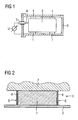
- FIG. 1 shows a simplified representation of a section through an arrangement consisting of a fuel cell module 2, which is mounted by means of insulators 1 in a pressure vessel 3.
- the pressure vessel 3 encloses the fuel cell module gas-tight and waterproof and serves to protect the fuel cell module 2 from mechanical damage and / or environmental influences and to prevent the escape of operating gases from the fuel cell module to the surrounding atmosphere.
- a power connection 4 is guided via a feedthrough capacitor 5 from the pressure vessel 3.
- a high insulation resistance (usually 10 M ⁇ ) must be present between the pressure vessel 3 and the electrical connection 5. This insulation resistance is permanently monitored during operation of the fuel cell module in a fuel cell system with the aid of a measuring voltage source U and shuts off the fuel cell system when it falls below a limit value.
- the fuel cell module 2 During operation of the fuel cell module 2, electric energy, heat and pure water are generated from hydrogen and oxygen. In operation, therefore, the fuel cell module 2 and the surrounding atmosphere in the pressure vessel 3 is warm and humid. After switching off the fuel cell module 2, the fuel cell module and thus also the surrounding atmosphere in the pressure vessel 3 cools, the moisture in the atmosphere condenses and precipitates on the surfaces of the insulators 1. The precipitating moisture forms drops of water on these surfaces connect to a water film wetting the surface, which would lower the insulation resistance of the insulators 1 to 1 M ⁇ or less.
- each of the insulators has a hydrophobic surface 6 at the points of contact with the pressure vessel atmosphere.
- the insulator 1 has for this purpose a core 7 made of an insulating, preferably non-hydrophobic material, e.g. made of a plastic or ceramic material, which has a hydrophobic surface coating 8.
- the hydrophobic surface coating 8 preferably consists entirely or partially of a hydrophobic material which can be dissolved in a solvent.
- this material consists of an amorphous fluoropolymer, in particular an amorphous modification of Teflon® (for example, an amorphous copolymer of 65-99 mole% perfluoro-2,2-dimethyl-1,3-dioxole with a complimentary amount of tetrafluoroethylene, from DuPont Fluoroproducts under the US Pat Product name Teflon®AF available).
- Teflon® for example, an amorphous copolymer of 65-99 mole% perfluoro-2,2-dimethyl-1,3-dioxole with a complimentary amount of tetrafluoroethylene, from DuPont Fluoroproducts under the US Pat Product name Teflon®AF available.
- the surface coating 8 consists of a polysiloxane compound or of alkylsilanes, in particular alkyl-aryl-silanes or halogen-alkyl-aryl-silanes.
- the surface coating 8 causes the condensed water droplets do not connect to a continuous film of water, but drain or occasionally remain without connection. It can thus be maintained even when cooling the fuel cell module 2 and condensation of the humidity of the atmosphere in the pressure vessel 3, the desired high insulation resistance between the pressure vessel 3 and the electrical terminals 5. Drying of the atmosphere in the pressure vessel 3 or a safety shutdown of Fuel cell module 2 on cooling is therefore not required.
- a thickness of the surface coating in the range of nanometers to micrometers may be sufficient.
- suitable layer thicknesses in the micrometer range and with amorphous Teflon even suitable layer thicknesses in the nanometer range can be achieved.
- the thickness must only be chosen so that it is sufficiently water-repellent and applied in the protected area without interruptions. The effectiveness of the coating can then be visually checked by simply wetting with pure water.
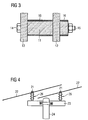
- FIG. 3 shows the use of insulators 11 according to the invention with hydrophobic surfaces 16 for fastening and mutual support of two electrical conductors 12, 13.
- the two conductors 12, 13 and the insulators 11 are in this case pressed together by means of a screw connection 14, 15.
- FIG. 4 shows a mounting of electrical overhead lines 22 by means of insulators 21 with hydrophobic surfaces 26 on a cross member 23 of a roof rack 24th
Landscapes
- Life Sciences & Earth Sciences (AREA)
- Engineering & Computer Science (AREA)
- Manufacturing & Machinery (AREA)
- Sustainable Development (AREA)
- Sustainable Energy (AREA)
- Chemical & Material Sciences (AREA)
- Chemical Kinetics & Catalysis (AREA)
- Electrochemistry (AREA)
- General Chemical & Material Sciences (AREA)
- Physics & Mathematics (AREA)
- Spectroscopy & Molecular Physics (AREA)
- Fuel Cell (AREA)
- Insulating Bodies (AREA)
- Organic Insulating Materials (AREA)
Priority Applications (6)
| Application Number | Priority Date | Filing Date | Title |
|---|---|---|---|
| EP20050016096 EP1748449A1 (fr) | 2005-07-25 | 2005-07-25 | Isolateur avec une capacité augmentée d'isolation |
| PCT/EP2006/064562 WO2007012627A1 (fr) | 2005-07-25 | 2006-07-24 | Isolateur a pouvoir isolant accru |
| KR1020087004305A KR101023861B1 (ko) | 2005-07-25 | 2006-07-24 | 절연 용량이 향상된 절연체 |
| EP06777921.5A EP1908082B1 (fr) | 2005-07-25 | 2006-07-24 | Isolateur avec une capacité augmentée d'isolation |
| US11/989,213 US7800003B2 (en) | 2005-07-25 | 2006-07-24 | Insulator with enhanced insulating capacity |
| ES06777921.5T ES2582193T3 (es) | 2005-07-25 | 2006-07-24 | Aislante con capacidad de aislamiento elevada |
Applications Claiming Priority (1)
| Application Number | Priority Date | Filing Date | Title |
|---|---|---|---|
| EP20050016096 EP1748449A1 (fr) | 2005-07-25 | 2005-07-25 | Isolateur avec une capacité augmentée d'isolation |
Publications (1)
| Publication Number | Publication Date |
|---|---|
| EP1748449A1 true EP1748449A1 (fr) | 2007-01-31 |
Family
ID=35448122
Family Applications (2)
| Application Number | Title | Priority Date | Filing Date |
|---|---|---|---|
| EP20050016096 Withdrawn EP1748449A1 (fr) | 2005-07-25 | 2005-07-25 | Isolateur avec une capacité augmentée d'isolation |
| EP06777921.5A Not-in-force EP1908082B1 (fr) | 2005-07-25 | 2006-07-24 | Isolateur avec une capacité augmentée d'isolation |
Family Applications After (1)
| Application Number | Title | Priority Date | Filing Date |
|---|---|---|---|
| EP06777921.5A Not-in-force EP1908082B1 (fr) | 2005-07-25 | 2006-07-24 | Isolateur avec une capacité augmentée d'isolation |
Country Status (5)
| Country | Link |
|---|---|
| US (1) | US7800003B2 (fr) |
| EP (2) | EP1748449A1 (fr) |
| KR (1) | KR101023861B1 (fr) |
| ES (1) | ES2582193T3 (fr) |
| WO (1) | WO2007012627A1 (fr) |
Cited By (2)
| Publication number | Priority date | Publication date | Assignee | Title |
|---|---|---|---|---|
| EP2009646A1 (fr) * | 2007-06-27 | 2008-12-31 | ABB Research Ltd. | Isolateur électrique et son procédé de fabrication |
| CN105845294A (zh) * | 2016-06-16 | 2016-08-10 | 江苏南瓷绝缘子股份有限公司 | 一种大型电力棒绝缘子毛坯的电阴干方法 |
Families Citing this family (6)
| Publication number | Priority date | Publication date | Assignee | Title |
|---|---|---|---|---|
| GB2456316B (en) * | 2008-01-10 | 2012-02-15 | Technip France | Umbilical |
| CN103500621A (zh) * | 2013-09-26 | 2014-01-08 | 国家电网公司 | 一种输电线路的瓷绝缘表面处理方法 |
| DE102015213653A1 (de) | 2015-07-21 | 2017-01-26 | Schaeffler Technologies AG & Co. KG | Schwingungsdämpfer |
| KR102299950B1 (ko) | 2017-01-05 | 2021-09-08 | 주식회사 엘지에너지솔루션 | 소수성 표면처리를 이용한 배터리 모듈 및 제작방법 |
| KR20220058572A (ko) * | 2019-09-02 | 2022-05-09 | 솔베이 스페셜티 폴리머스 이태리 에스.피.에이. | 플루오로중합체를 포함하는 하이브리드 복합 전해질 |
| CN114497639B (zh) * | 2021-12-24 | 2023-10-20 | 重庆明天氢能科技有限公司 | 一种提高燃料电池系统绝缘电阻的方法 |
Citations (6)
| Publication number | Priority date | Publication date | Assignee | Title |
|---|---|---|---|---|
| DE1814498A1 (de) * | 1968-12-13 | 1970-06-25 | Ruhrtal Elek Zitaetsgesellscha | Oberflaechenbehandelte Isolatoren |
| GB2058482A (en) * | 1979-07-12 | 1981-04-08 | Feldmesser K | Improvements in or relating insulators especially for use at radio frequencies |
| GB2065386A (en) * | 1979-11-22 | 1981-06-24 | Barber P F | Electrical installation using elongate insulators and protective assemblies therefor |
| GB1598951A (en) * | 1977-02-25 | 1981-09-30 | Siemens Ag | Insulator |
| GB1603765A (en) * | 1977-05-24 | 1981-11-25 | Fidenza Vetraria Spa | Polytetrafluoroethylene-coated glass electrical insulator |
| WO2004105172A1 (fr) * | 2003-05-22 | 2004-12-02 | Nissan Motor Co., Ltd. | Structure de montage isolante, systeme de surveillance d'isolants et procede de surveillance d'isolants pour piles a combustible |
Family Cites Families (5)
| Publication number | Priority date | Publication date | Assignee | Title |
|---|---|---|---|---|
| DE2650363C2 (de) * | 1976-11-03 | 1985-10-10 | Rosenthal Technik Ag, 8672 Selb | Verbundisolator für Hochspannungsfreiluft-Anwendungen |
| DE3267216D1 (en) * | 1981-06-26 | 1985-12-12 | Verma Manoranjan Prasad | High voltage resistor for open air insulating arrangements |
| TW406091B (en) * | 1997-12-18 | 2000-09-21 | Asahi Glass Co Ltd | Fluorine-containing polymer composition and process for forming a thin film thereof |
| JP3968899B2 (ja) | 1997-12-18 | 2007-08-29 | 旭硝子株式会社 | 含フッ素重合体組成物および薄膜を得る方法 |
| DE19835916A1 (de) * | 1998-08-07 | 2000-02-17 | Siemens Ag | Isolator |
-
2005
- 2005-07-25 EP EP20050016096 patent/EP1748449A1/fr not_active Withdrawn
-
2006
- 2006-07-24 US US11/989,213 patent/US7800003B2/en not_active Expired - Fee Related
- 2006-07-24 ES ES06777921.5T patent/ES2582193T3/es active Active
- 2006-07-24 KR KR1020087004305A patent/KR101023861B1/ko not_active Expired - Fee Related
- 2006-07-24 WO PCT/EP2006/064562 patent/WO2007012627A1/fr not_active Ceased
- 2006-07-24 EP EP06777921.5A patent/EP1908082B1/fr not_active Not-in-force
Patent Citations (6)
| Publication number | Priority date | Publication date | Assignee | Title |
|---|---|---|---|---|
| DE1814498A1 (de) * | 1968-12-13 | 1970-06-25 | Ruhrtal Elek Zitaetsgesellscha | Oberflaechenbehandelte Isolatoren |
| GB1598951A (en) * | 1977-02-25 | 1981-09-30 | Siemens Ag | Insulator |
| GB1603765A (en) * | 1977-05-24 | 1981-11-25 | Fidenza Vetraria Spa | Polytetrafluoroethylene-coated glass electrical insulator |
| GB2058482A (en) * | 1979-07-12 | 1981-04-08 | Feldmesser K | Improvements in or relating insulators especially for use at radio frequencies |
| GB2065386A (en) * | 1979-11-22 | 1981-06-24 | Barber P F | Electrical installation using elongate insulators and protective assemblies therefor |
| WO2004105172A1 (fr) * | 2003-05-22 | 2004-12-02 | Nissan Motor Co., Ltd. | Structure de montage isolante, systeme de surveillance d'isolants et procede de surveillance d'isolants pour piles a combustible |
Cited By (2)
| Publication number | Priority date | Publication date | Assignee | Title |
|---|---|---|---|---|
| EP2009646A1 (fr) * | 2007-06-27 | 2008-12-31 | ABB Research Ltd. | Isolateur électrique et son procédé de fabrication |
| CN105845294A (zh) * | 2016-06-16 | 2016-08-10 | 江苏南瓷绝缘子股份有限公司 | 一种大型电力棒绝缘子毛坯的电阴干方法 |
Also Published As
| Publication number | Publication date |
|---|---|
| EP1908082B1 (fr) | 2016-04-13 |
| US7800003B2 (en) | 2010-09-21 |
| ES2582193T3 (es) | 2016-09-09 |
| EP1908082A1 (fr) | 2008-04-09 |
| KR101023861B1 (ko) | 2011-03-22 |
| WO2007012627A1 (fr) | 2007-02-01 |
| US20090145657A1 (en) | 2009-06-11 |
| KR20080030105A (ko) | 2008-04-03 |
Similar Documents
| Publication | Publication Date | Title |
|---|---|---|
| WO2009135691A1 (fr) | Boîte de jonction, utilisations d'une boîte de jonction et procédé | |
| EP3639282B1 (fr) | Conduite haute tension enfichable et appareil électrique comportant une conduite haute tension enfichable | |
| EP1908082B1 (fr) | Isolateur avec une capacité augmentée d'isolation | |
| EP2907145B1 (fr) | Composant ceramique avec une couche protéctrice et son procédé de fabrication | |
| EP1314171B1 (fr) | Compose electrique et son procede de production | |
| WO2000008659A2 (fr) | Isolateur | |
| DE3212738A1 (de) | Verfahren zur quasihermetischen, rueckwirkungsarmen abdeckung empfindlicher physikalischer strukturen | |
| EP0325203B1 (fr) | Procédé de fabrication d'une couche en dioxyde de manganèse de condensateurs à électrolyte solide | |
| EP3435493A1 (fr) | Traversée de haute tension enfichable et installation haute tension comprenant un traversée de haute tension enfichable | |
| EP3679610B1 (fr) | Pile électrochimique et son procédé de fabrication | |
| WO2018001863A1 (fr) | Transducteur de mesure pour les techniques de mesure haute tension | |
| DE102011017095A1 (de) | Kontaktmittel für ein Zündkerzensystem | |
| DE202022103899U1 (de) | Zellkontaktierungssystem sowie Energiespeicher | |
| DE3001943A1 (de) | Einrichtung zum ueberspanneungsschutz | |
| DE102023130538B3 (de) | Verfahren zum Verschalten von Batteriezellen unter Einhaltung von Luft und Kriechstrecken | |
| EP1389337A1 (fr) | Ensemble constitue d'un couvercle metallique et d'un boitier metallique pour un dispositif de mesure et procede de fabrication dudit ensemble | |
| DE10112801C2 (de) | Verfahren zur Herstellung eines Elektrischen Bauelements und dessen Verwendung | |
| DE102021115851A1 (de) | Leiterplatte | |
| WO2023232665A1 (fr) | Composant actif revêtu dans un dispositif haute tension et procédé d'augmentation de la rigidité diélectrique | |
| DE102023119064A1 (de) | Vibrationssensor mit Schutzschicht und Verfahren zur Herstellung eines Vibrationssensors | |
| WO2014202386A1 (fr) | Installation de distribution haute ou moyenne tension dotée d'un gaz isolant | |
| DE7602482U1 (de) | DurchfUhrungselektrode | |
| DE4208758A1 (de) | Verwendung von polyarylenethersulfonen und polyarylenetherketonen zur umhuellung von elektrischen und elektronischen bauelementen | |
| DD256010A1 (de) | Dielektrischer keramischer koerper | |
| DE202005021266U1 (de) | Elektrisches Gerät |
Legal Events
| Date | Code | Title | Description |
|---|---|---|---|
| PUAI | Public reference made under article 153(3) epc to a published international application that has entered the european phase |
Free format text: ORIGINAL CODE: 0009012 |
|
| AK | Designated contracting states |
Kind code of ref document: A1 Designated state(s): AT BE BG CH CY CZ DE DK EE ES FI FR GB GR HU IE IS IT LI LT LU LV MC NL PL PT RO SE SI SK TR |
|
| AX | Request for extension of the european patent |
Extension state: AL BA HR MK YU |
|
| AKX | Designation fees paid | ||
| STAA | Information on the status of an ep patent application or granted ep patent |
Free format text: STATUS: THE APPLICATION IS DEEMED TO BE WITHDRAWN |
|
| 18D | Application deemed to be withdrawn |
Effective date: 20070801 |
|
| REG | Reference to a national code |
Ref country code: DE Ref legal event code: 8566 |