EP1748619B1 - Méthode pour effectuer une connection de communications directe et sécurisée entre deux réseaux - Google Patents
Méthode pour effectuer une connection de communications directe et sécurisée entre deux réseaux Download PDFInfo
- Publication number
- EP1748619B1 EP1748619B1 EP06117195A EP06117195A EP1748619B1 EP 1748619 B1 EP1748619 B1 EP 1748619B1 EP 06117195 A EP06117195 A EP 06117195A EP 06117195 A EP06117195 A EP 06117195A EP 1748619 B1 EP1748619 B1 EP 1748619B1
- Authority
- EP
- European Patent Office
- Prior art keywords
- communication
- network
- communication device
- switching unit
- connection
- Prior art date
- Legal status (The legal status is an assumption and is not a legal conclusion. Google has not performed a legal analysis and makes no representation as to the accuracy of the status listed.)
- Active
Links
Images


Classifications
-
- H—ELECTRICITY
- H04—ELECTRIC COMMUNICATION TECHNIQUE
- H04L—TRANSMISSION OF DIGITAL INFORMATION, e.g. TELEGRAPHIC COMMUNICATION
- H04L63/00—Network architectures or network communication protocols for network security
- H04L63/02—Network architectures or network communication protocols for network security for separating internal from external traffic, e.g. firewalls
- H04L63/029—Firewall traversal, e.g. tunnelling or, creating pinholes
-
- H—ELECTRICITY
- H04—ELECTRIC COMMUNICATION TECHNIQUE
- H04L—TRANSMISSION OF DIGITAL INFORMATION, e.g. TELEGRAPHIC COMMUNICATION
- H04L63/00—Network architectures or network communication protocols for network security
- H04L63/04—Network architectures or network communication protocols for network security for providing a confidential data exchange among entities communicating through data packet networks
- H04L63/0428—Network architectures or network communication protocols for network security for providing a confidential data exchange among entities communicating through data packet networks wherein the data content is protected, e.g. by encrypting or encapsulating the payload
Definitions
- the communication networks to be supervised are preferably private communication networks which are protected by protective measures, such as a firewall, from foreign and unauthorized connection setup attempts of further communication devices from the public communication network, for example the Internet.
- a firewall is to be understood as the entirety of all measures for shielding a local or private communication network against external access, these being used predominantly for monitoring the data traffic from a public to the private communication network to be monitored.
- Such firewalls can be implemented both in terms of hardware and software, depending on the requirements of the communication applications or services to be monitored or on the degree of security.
- security mechanisms are usually implemented which prevent the direct establishment of a connection via a communication application from the outside into the private communication network.
- firewall implementation In principle, a distinction is made between three types of firewall implementation: "packet filtering”, “circuit relay” and “application gateway” or “application-level gateway”. These can also be realized as combined security concepts.
- the data packets entering and leaving the communications network at the respective layer level i.
- the data link layer, the network layer or the transport layer are analyzed and controlled on the basis of predefined tables.
- the data packet content is interpreted and verified via a filter module, specifically the headers of the data packets are checked for their compliance with respect to the given communication control layer.
- the Circuit Relay concept consists of a subnet, an in-network and an off-grid router unit, and a host communication application as a link partner.
- the host communication application performs the data communication, thereby avoiding network structure transparency to the outside.
- a login to the host communication application is required, which requires an access authorization.
- a monitoring of the data packet stream flowing after the connection has been established does not take place.
- the safest but also the most technically complex form of implementation of a firewall represents the application-level gateway concept.
- the private and the other, for example, public communication network are logically and physically decoupled from each other. Access to the private communications network requires identification and authentication.
- the incoming data packets of a communication connection are received in a proxy server unit and transmitted via a proxy communication application in the private communication network.
- a proxy communication application in the private communication network.
- different service-specific gateways may be provided in the proxy server unit, for example for Telnet, e-mail, http, etc.
- a direct network-spanning communication connection is required between the first and second private communication networks.
- the connection is usually made via a public communication network, such as the Internet.
- a public communication network such as the Internet
- SSH Secure Shell
- Telnet Telnet
- FTP File Transfer Protocol
- POP3 post office protocol
- Secure Shell tunnel connection is established via such a "Secure Shell” network protocol, via the data according to the used transmission protocol “tunnelled” and thus can be transmitted tap-proof.
- WO03 / 036910 discloses a method for establishing a secure communication connection between a first communication device of a first communication network and a second communication device of a second communication network.
- the object of the present invention is to provide a flexible and secure method by which the establishment of a direct, cross-network and secure communication link between a first communication device of a first communication network and a second communication device of a second, topologically completely separated from the first communication network communication network while maintaining the strict safety regulations within the second communication device.
- the essential aspect of the inventive method for establishing a direct, network-spanning and tamper-proof communication connection between a first communication device of a first communication network and at least a second communication device of another second communication network via at least a first connected to the first communication network switching unit, a second with at least one of the other second Communication networks connected switching unit and provided in the second communication network and connectable to the at least one second communication device network internal switching unit, is the fact that before setting up the communication connection from the network internal switching unit from the second communication network, a secure shell tunnel connection to the second switching unit is constructed, and starting from the first communication device via the first and second switching unit, the secure shell tunnel connection and the network-internal switching unit to the second communication device a direct, cross-network and secure communication connection is established.
- a secure connection in the form of a secure shell tunnel connection from the network-internal switching unit to the second switching center or application-level firewall unit is established before the direct and cross-network communication connection is established and thus the "customer firewall" tunnelled.
- This is done by the customer through a bootable Secure Shell client application as well as, for example a secure encrypted secure shell tunnel from a configuration configured as a network-internal switching unit in the second communication network communication device to the second application-level firewall unit.
- a direct, cross-network and secure communication link between the client computer and the service computer is then created by the service provider without modifications of the security settings in the second communication network via the secure shell tunnel connection, the client communication device and the server Communication device are arranged in topologically separate communication networks such as Firmenintranets.
- the symbolic address indicator forms, for example, a type of "connection ticket", which contains all the data required for the establishment of the direct, network-spanning and tamper-proof communication connection.
- Fig. 1 is a schematic block diagram of a communication system 1, in which a plurality of private communication networks 2, for example, a first, second and third communication network 2.1, 2.2, 2.3 via in each case at least one switching center, for example, a first, second and third switching unit 3.1, 3.2, 3.3 at a public communication network 4, preferably the Internet are connected.
- a plurality of private communication networks 2 for example, a first, second and third communication network 2.1, 2.2, 2.3 via in each case at least one switching center, for example, a first, second and third switching unit 3.1, 3.2, 3.3 at a public communication network 4, preferably the Internet are connected.
- the number, structure and arrangement of the private communication networks 2 with respect to the public communication network 4 are selected by way of example and can be varied as desired.
- the first communication network 2.1 represents, for example, the intranet of a service provider who is responsible for the maintenance of, for example, the second and / or third communication network 2.2, 2.3, which is completely topologically separate from the first communication network 2.1.
- the establishment of a direct, cross-network and secure communication link 8 between the first communication network 2.1 via the public communication network 4 to be maintained second or third communication network 2.2, 2.3 is required.
- the second and third communication networks 2.2, 2.3 are also formed as intranets which are self-contained, i.e. self-contained. represent topologically independent communication networks 2.
- the first to third communication network 2.1 - 2.3 each have a plurality of networked communication devices 5.x, which, for example, as computer systems or
- the communication devices 5 have communication ports (not shown in the figures) via which the communication applications executed on the communication devices 5 communicate.
- a communication port is to be understood in each case as a communication channel identified via a unique communication port number Px, individual communication port numbers Px being reserved for predetermined communication applications in a manner known per se.
- a first, second and third communication device 5.11, 5.12, 5.13 are provided in the first communication network 2.1.
- the second communication network 2.2 includes by way of example a first to fourth communication device 5.21, 5.22, 5.23, 5.24, wherein the third communication network 2.3 has a first to third communication device 5.31, 5.32, 5.33.
- the individual communication devices 5.11 - 5.13, 5.21 - 5.24, 5.31 - 5.33 of a communication network 2.1, 2.2, 2.3 are in each case networked via connecting lines 6 within the respective private communication network 2.1, 2.2, 2.3.
- the first communication network 2.1 is connected to the first communication network 2.1, which establishes a connection from the first communication network 2.1 to the public communication network 4.
- the second and third communication network 2.2, 2.3 with the public communication network 4 also the second and third switching unit 3.2, 3.3 are provided.
- the connecting lines 6 of the respective communication network 2.1 to 2.3 are preferably routed respectively to the upstream switching unit 3.1 to 3.3, so that a direct connection between the individual communication devices 5.11 - 5.13, 5.21 to 5.23, 5.31 - 5.33 and the associated switching unit 3.1 to 3.3, for example, via a router unit, not shown in the figures.
- the second and third switching unit 3.2, 3.3 and the with This connected second or third communication network 2.2, 2.3 so-called "demilitarized zones" be provided.
- the first to third switching units 3.1 to 3.3 are configured by way of example in each case as an application-level firewall unit (ALF), preferably as a first, second and third ALF unit 3.1, 3.2, 3.3.
- the first ALF unit 3.1 has a first proxy server unit 7.1, the second ALF unit 3.2 a second proxy server unit 7.2 and the third ALF unit 3.2, a third proxy server unit 7.3, via which the Proxy functionalities of the first to third ALF units 3.1, 3.2, 3.3 are implemented.
- the proxy server units 7.1-7.3 thus perform a logical and physical decoupling on the Internet Protocol (IP) level of the respective private communication network 2.1 to 2.3 from the public communication network 4.
- IP Internet Protocol
- the proxy server units 7.1 to 7.3 When establishing a communication connection 8 from a private communication network 2 in the public communication network or the Internet 4, an automatic address translation is performed on the upstream first proxy server unit 7.1.
- the proxy server units 7.1 to 7.3 in this case send the connection requests received from the respective private communication network 2.1 to 2.3 under their own address with associated communication port number Px to the public communication network 4 and analogously forward the connection requests received from the public communication network 4 to the corresponding Communication device 5 of the private communication network 2.1 to 2.3 on.
- the authorization for access from outside the respective private communication network 2.2 to communication units 5.22 within the respective private communication network 2.2 thus takes place exclusively via the first to third proxy server units 7.1 to 7.3, which collects all requests and thus establishes a direct communication connection 8 between the communication link 8 initiating prevents first located outside of the communication network to be protected communication device 5.11 and a second located in the protected communication network 2.2 communication device 5.22.
- the actual structure as well as the internal network address numbers, for example the Internet Protocol addresses and the communication port addresses of the respective communication device within the protected private communication network 2.2 are thus not visible from the outside and thus not directly accessible by a located outside the private communication network 2.2 communication device 5.11.
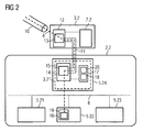
- Fig. 2 the second communication network 2.2 with connected second ALF unit 3.2 is shown by way of example in a schematic detail representation.
- a first control unit 12 with a "Secure Shell” (SSH) server application 13 is provided in the second ALF unit 3.2.
- the control unit 12 is connected to the second proxy server unit 7.2.
- SSH Secure Shell
- the fourth communication device 5.24 of the second communication network 2.2 is configured by way of example as a network-internal switching center 3.2 *, which has a second control unit 14 with a "Secure Shell” (SSH) client application 15.
- the second control unit 14 is connected to a storage medium 17, preferably to a removable storage medium, for example a CD, DVD or floppy disk unit, in which the switching data 18 (IP addresses, communication port numbers, gateways) required for setting up a secure shell tunnel connection 11 ) are stored.
- SSH Secure Shell
- a third control unit 19 is provided, on which a communication application 16 is executed and which cooperates by way of example with the SSH client application 15 executed in the second control unit 14.
- the fourth communication device 5.24 is initialized by means of a restart with a bootable SSH client application 15 as the network-internal switching unit 3.2 *.
- the SSH client application 15 loads the switching data 18 stored in the storage medium 17 and required for establishing the secure shell tunnel connection 11 into the second control unit 14.
- the bootable SSH client application 15 is stored on a CD and is loaded on booting of the fourth communication device 5.24 into the second control unit 14, the configuration data 18 being stored for example on a floppy disk.
- the switch data 18 is read from the floppy disk by the SSH client application 15.
- the switching data 18 comprises, for example, the first secure shell communication port number SP1 assigned to the secure shell server application 13, the unique network internal communication port number Px *, the unique network internal switching address number Vx * of the second switching unit 3.2 and the secure shell client Application 15 associated second secure shell communication port number SP2 the fourth communication device 5.24.
- a connection to the SSH server application 13 is established via the SSH client application 15.
- the parameters necessary for setting up the secure secure shell tunnel connection 11 are exchanged in a manner known per se, and then the secure shell tunnel connection 11 is established, maintained and possibly dismantled again.
- a secure shell tunnel connection 11 has a plurality of transmission channels.
- each individual communication device 5.21 to 5.24 of the second communication network 2.2 is assigned at least one transmission channel of the secure shell tunnel connection 11.
- FIG. 3 are explained with reference to a schematic flow chart, the other steps of the following connection structure.
- all the communication devices 5.21 - 5.24, 5.31 - 5.33 of the communication networks 2.2, 2.3 to be serviced, as well as the communication applications provided on the communication devices 5.21 - 5.24, 5.31 - 5.33, are assigned unique symbolic address numbers Vx, Sx, Ax and in the network devices mentioned stored, for example, in the form of data records, wherein the data records can be stored in one or more storage units (not shown in the figures) or storage media 17 provided in said network devices.
- a symbolic address indicator 9 is generated in the first communication device 5.11 of the first communication network 3.1 (intranet of the service provider).
- the structure of such a symbolic address indicator 9 is in FIG. 4 shown schematically.
- the symbolic address indicator 9 has a first to third symbolic address component 9.1 to 9.3, the first symbolic address component 9.1 being the symbolic switching address number Vx assigned to the switching center or the ALF unit 3.2, 3.3, the second symbolic address component 9.2 being the respective communication device 5 associated symbolic system address number Sx and the third symbolic address component 9.3 comprises the respective communication application in the second or third communication device 2.2, 2.3 associated symbolic application address number Ax.
- the combination of a symbolic exchange address number Vx, a symbolic system address number Sx and a symbolic application address number Ax results in a unique symbolic address indicator 9 relating to the first communication network 2.1, which indicates the connection resources required to establish the direct network-wide communication connection 8.
- the symbolic switch address number Vx may be, for example, the Internet Protocol address of the second or third ALF unit 3.2, 3.3.
- first to third address components 9.1 to 9.3 are selected by way of example and can be supplemented by suitable additional components or arranged in different order to each other.
- additional components or arranged in different order to each other.
- further information such as the name, the e-mail address or the identifier of the service employee can be transmitted via the symbolic address indicator 9 with.
- the symbolic address indicator 9 generated in the first communication device 5.11 of the first communication network 2.1 is transmitted via the connection lines 6 of the first communication network 1 to the first exchange 3.1, ie to the proxy server unit 7.1 of the first ALF unit 3.1 transmitted and stored in this. This corresponds to the second step of the in Fig. 3 illustrated flowchart.
- an identifier identifying the first communication device 5.11 preferably its Internet protocol address IP 5.11, is stored in the first ALF unit 3.1, so that in the first ALF unit 3.1 there is a link between the stored symbolic address indicator 9 and the first communication device 5.11 forming the starting point of the communication connection 8 described by the symbolic address indicator 9.
- a connection request is initiated to establish the direct cross-network communication link 8 via a communication application provided in the first communication device 5.11, for example a "Telnet client application” or a "PC-Anywhere client application”. transmitted from the first communication device 5.11 to the first ALF unit 3.1.
- the connection request has at least the identification IP 5.11 identifying the first communication device 5.11 and / or the communication application , preferably the Internet protocol address of the first communication device 5.11 and / or the communication port number assigned to said communication application.
- the associated symbolic address indicator 9 which contains the symbolic address numbers Vx, Sx, Ax required for the further connection establishment is determined in the first proxy server unit 7.1 (fourth step).
- a virtual private network (VPN) tunnel connection 10 is provided which ensures secure data communication over the Internet 4 .
- the VPN tunnel connection 10 between the first and second ALF units 3.1, 3.2 forms a further topologically from the first to third communication network 2.1, 2.2, 2.3 independent communication network.
- the symbolic address indicator 9 is at least partially transmitted to the second proxy server unit 7.2 of the determined second ALF unit 3.2 and stored there.
- the network internal system address number Sx * of the second communication device 5.22 which is unique relative to the second communication network 2.2, is determined in a sixth step on the basis of the symbolic system address number Sx contained in the second symbolic address component 9.2 of the transmitted symbolic address indicator 9. For this purpose, symbolic system address number Sx is compared with the memory entries stored in the second switching unit 3.2.
- the assigned symbolic application address number Ax is determined via the second proxy server unit 7.2 and this is compared with the memory entries. Subsequently, via the first secure-shell communication port number SP1 assigned to the symbolic application address number Ax, the connection is established via the secure shell tunnel connection 11 to the second secure-shell communication port number SP2 via the second proxy server unit 7.2.
- the SSH client application 15 executed in the second control unit 14 of the network-internal switching unit 3.2 * can be addressed via the second secure-shell communication port number SP2.
- connection data 20 stored in the memory unit 17, which after the establishment of the secure shell tunnel connection 11 from the second exchange 3.2 to the network-internal exchange 3.2 *, a connection is made to the communication application 16 implemented in the third control unit 19 of the second communication device 5.22.
- suitable communication applications such as a "Telnet daemon application” or "PC Anyware host application” are provided to realize the client-server principle, which via the first and second proxy server unit 7.1, 7.2 communicate with the provided in the first communication device 5.11 "Telnet client application” or "PC Anywhere client application”.
- TCP Transmission Control Protocol
- the first to third switching units 3.1, 3.2, 3.3 may each be provided in multiple, each of which has a further via a different link through the public communication network 4 virtual private network (VPN) tunnel connection (not shown in the figures) for establishing a direct, cross-network and secure communication link 8 are connected to each other.
- VPN virtual private network
- connection data 20 relevant for establishing the connection after the establishment of the secure shell Tunnel connection 11 from the second and third switching unit 3.2, 3.3 are loaded.
- the individual process steps required for setting up the secure shell tunnel connection 11 can be printed on the CD cover of the SSH client application 15 stored on a bootable CD as a type of "operating manual".
- the communication device 5.24 configured as network-internal switching unit 3.2 * can additionally be used in the respective communication network 2.2, 2.3 for further applications. It is also possible to use a mobile communication device, for example a laptop, as the network-internal switching unit 3.2 *.
Landscapes
- Engineering & Computer Science (AREA)
- Computer Security & Cryptography (AREA)
- Computer Hardware Design (AREA)
- Computing Systems (AREA)
- General Engineering & Computer Science (AREA)
- Computer Networks & Wireless Communication (AREA)
- Signal Processing (AREA)
- Data Exchanges In Wide-Area Networks (AREA)
Claims (18)
- Procédé pour la mise en place d'au moins une liaison de communication (8) directe, couvrant les réseaux et anti-écoute entre un premier dispositif de communication (5.11) d'un premier réseau de communication (2.1) et au moins un second dispositif de communication (5.22) d'un second réseau de communication (2.2) au moyen d'au moins une première unité de commutation (3.1) reliée au premier réseau de communication (2.1), d'une seconde unité de commutation (3.2) reliée au second réseau de communication (2.2) et d'une unité de commutation (3.2*) interne au réseau, prévue dans le second réseau de communication (2.2) et pouvant être reliée au au moins un second dispositif de communication (5.22),- dans lequel, avant l'établissement de la liaison de communication (8), au moins un autre dispositif de communication (5.24) prévu dans le second réseau de communication (2.2) est configuré à l'aide d'une application client Secure Shell (15) bootable comme unité de commutation (3.2*) interne au réseau,- dans lequel l'unité de commutation (3.2*) interne au réseau établit par l'application client Secure Shell (15) à partir du second réseau de communication (2.2) une connexion tunnel Secure Shell (11) avec la seconde unité de commutation (3.2), et- dans lequel, à partir du premier dispositif de communication (5.11), une liaison de communication (8) directe, couvrant les réseaux et anti-écoute est établie avec le second dispositif de communication (5.22) par l'intermédiaire de la première et de la seconde unité de commutation (3.1, 3.2), de la connexion tunnel Secure Shell (11) et de l'unité de commutation (3.2*) interne au réseau.
- Procédé selon la revendication 1, dans lequel l'application client Secure Shell (15) bootable lit les données de commutation (18) nécessaires pour l'établissement de la connexion tunnel Secure Shell (11) à partir d'un support de stockage (17) et établit la connexion tunnel Secure Shell (11) en fonction des données de commutation (18).
- Procédé selon la revendication 2, dans lequel, comme données de commutation (18), on lit au moins le premier numéro de port de communication Secure Shell (SP1), attribué à une application de serveur Secure Shell (13), le numéro d'adresse de commutation (Vx*) interne au réseau de la seconde unité de commutation (3.2, 3.3) et le second numéro de port de communication Secure Shell (SP2), attribué à l'application client Secure Shell (15), du dispositif de communication (5.24) configuré comme unité de commutation (3.2*) interne au réseau.
- Procédé selon l'une quelconque des revendications 1 à 3, dans lequel après l'établissement réussi de la connexion tunnel Secure Shell (11), toutes les données de liaison (20) nécessaires pour l'établissement de la liaison avec le second dispositif de communication (5.22) sont transmises du second point de commutation (3.2) au point de commutation (3.2*) interne au réseau.
- Procédé selon l'une quelconque des revendications 1 à 4, dans lequel des numéros d'adresse (Vx, Sx, Ax) symboliques, uniques par rapport au premier réseau de communication (3.1) sont attribués au moins à la seconde unité de commutation (3.2), au second dispositif de communication (5.22) et au moins à une application de communication prévue dans le second dispositif de communication.
- Procédé selon la revendication 5, dans lequel un indicateur d'adresse (9) symbolique est formé au moins en partie à partir des numéros d'adresse (Vx, Sx, Ax) symboliques du second point de commutation (3.2) prévu pour l'établissement de la liaison de communication (8), d'au moins un second dispositif de communication (5.22) et d'au moins une application de communication (16) prévue sur ledit second dispositif de communication (5.22).
- Procédé selon la revendication 6, dans lequel des numéros d'adresse (Vx*, Sx*, Ax*) internes au réseau, uniques par rapport au second réseau de communication (3.2, 3.3) respectif sont attribués aux numéros d'adresse (Vx, Sx, Ax) symboliques, uniques par rapport au premier réseau de communication (2.1) à l'aide d'ensembles de données déposés dans la première et la seconde unité de commutation (3.1, 3.2) et les dispositifs de communication (5.21, 5.22, 5.23, 5.24, 5.31, 5.32) des seconds réseaux de communication (3.2, 3.3).
- Procédé selon l'une quelconque des revendications 5 à 7, dans lequel au moins un premier jusqu'à un troisième composant d'adresse (9.1 à 9.3) est formé à l'intérieur de l'indicateur d'adresse (9) symbolique, le premier composant d'adresse (9.1) contenant un numéro d'adresse de commutation (Vx) symbolique, le second composant d'adresse (9.2) contenant un numéro d'adresse de système (Sx) symbolique et le troisième composant d'adresse (9.3) contenant un numéro d'adresse d'application (Ax) symbolique.
- Procédé selon l'une quelconque des revendications précédentes, dans lequel l'indicateur d'adresse (9) symbolique est généré avant l'établissement de la liaison de communication (8) directe et couvrant les réseaux dans le premier réseau de communication (3.1).
- Procédé selon la revendication 9, dans lequel l'indicateur d'adresse (9) symbolique est généré dans le premier dispositif de communication (5.11), est transmis à la première unité de commutation (3.1) et est stocké dans la première unité de commutation (3.1).
- Procédé selon l'une quelconque des revendications 9 ou 10, dans lequel l'établissement de la liaison de communication (8) est initié au moyen d'une première application de communication, réalisée dans le premier dispositif de communication (5.11).
- Procédé selon l'une quelconque des revendications 9 à 11, dans lequel une demande de liaison avec au moins un code (IP5.11) identifiant le premier dispositif de communication (5.11) est transmise par l'application de communication du premier dispositif de communication (5.11) à la première unité de commutation (3.1) et l'indicateur d'adresse (9) symbolique spécifique est déterminé dans la première unité de commutation (3.1) à l'aide du code (IP5.11) transmis avec la demande de liaison.
- Procédé selon la revendication 12, dans lequel le numéro d'adresse de commutation symbolique (Vx), déterminé pour l'établissement de la liaison de communication (8), du second point de commutation (3.2) est déterminé dans la première unité de commutation (3.1) à l'aide du premier composant d'adresse (9.1) symbolique de l'indicateur d'adresse (9) symbolique, une liaison est établie avec la seconde unité de commutation (3.2) déterminée au moyen d'un troisième réseau de communication (4) et l'indicateur d'adresse (9) symbolique est transmis au moins partiellement à la seconde unité de commutation (3.2) déterminée.
- Procédé selon la revendication 13, dans lequel le premier numéro de port de communication Secure Shell (SP1) attribué de la connexion tunnel Secure Shell (11) est déterminé dans la seconde unité de commutation (3.2) à l'aide du numéro d'adresse de système (Sx) symbolique de l'indicateur d'adresse (9) symbolique par le biais des données de liaison (20) déposées dans la seconde unité de commutation (3.2) et l'établissement de liaison est poursuivi par l'intermédiaire de la connexion tunnel Secure Shell (11) et de l'unité de commutation (3.2*) interne au réseau avec le second dispositif de communication (5.22) du second réseau de communication (2.2).
- Procédé selon l'une quelconque des revendications précédentes, dans lequel au moins une connexion tunnel (10) Virtual Private Network (VPN) est établie entre la première unité de commutation et la seconde unité de commutation (3.1, 3.2).
- Procédé selon l'une quelconque des revendications précédentes, dans lequel les unités de commutation (3.1, 3.2, 3.3) sont réalisées respectivement par le biais d'une unité Application-Level-Firewall (ALF), lesquelles présentent chacune au moins une unité de serveur mandataire (7.1, 7.2, 7.3).
- Procédé selon l'une quelconque des revendications 12 à 16, dans lequel le code (IP5.11) identifiant le premier dispositif de communication (5.11) est formé au moins partiellement à partir de l'adresse de protocole Internet du premier dispositif de communication (5.11).
- Procédé selon l'une quelconque des revendications 11 à 17, dans lequel des applications de communication client et serveur (16) sont mises en oeuvre comme applications de communication (16) dans le premier et le second dispositif de communication (5.11, 5.22), applications dans lesquelles la transmission de données s'effectue au moyen d'une liaison de données Transmission Control Protocoll (TCP).
Applications Claiming Priority (1)
| Application Number | Priority Date | Filing Date | Title |
|---|---|---|---|
| DE102005035698A DE102005035698A1 (de) | 2005-07-27 | 2005-07-27 | Verfahren zum Aufbau einer direkten, netzübergreifenden und abhörsicheren Kommunikationsverbindung |
Publications (2)
| Publication Number | Publication Date |
|---|---|
| EP1748619A1 EP1748619A1 (fr) | 2007-01-31 |
| EP1748619B1 true EP1748619B1 (fr) | 2011-10-12 |
Family
ID=37401059
Family Applications (1)
| Application Number | Title | Priority Date | Filing Date |
|---|---|---|---|
| EP06117195A Active EP1748619B1 (fr) | 2005-07-27 | 2006-07-14 | Méthode pour effectuer une connection de communications directe et sécurisée entre deux réseaux |
Country Status (3)
| Country | Link |
|---|---|
| EP (1) | EP1748619B1 (fr) |
| AT (1) | ATE528898T1 (fr) |
| DE (1) | DE102005035698A1 (fr) |
Families Citing this family (1)
| Publication number | Priority date | Publication date | Assignee | Title |
|---|---|---|---|---|
| CN112738074B (zh) * | 2020-12-25 | 2023-02-24 | 成都鼎安华智慧物联网股份有限公司 | 一种网络隔离中实现Telnet通信的方法 |
Family Cites Families (6)
| Publication number | Priority date | Publication date | Assignee | Title |
|---|---|---|---|---|
| DE60100800T2 (de) * | 2000-02-25 | 2004-07-01 | Sun Microsystems, Inc., Santa Clara | Verfahren und einrichtung zur bereitstellung von einem hochverfügbaren computerdienst |
| US7200660B2 (en) * | 2001-08-10 | 2007-04-03 | Ininet Solutions Gmbh | Procedure and configuration in order to transmit data |
| US20030079121A1 (en) * | 2001-10-19 | 2003-04-24 | Applied Materials, Inc. | Secure end-to-end communication over a public network from a computer inside a first private network to a server at a second private network |
| US7325140B2 (en) * | 2003-06-13 | 2008-01-29 | Engedi Technologies, Inc. | Secure management access control for computers, embedded and card embodiment |
| DE10331307A1 (de) * | 2003-07-10 | 2005-02-10 | Siemens Ag | Vorrichtung und Verfahren sowie Sicherheitsmodul zur Sicherung eines Datenzugriffs eines Kommunikationsteilnehmers auf mindestens eine Automatisierungskomponente eines Automatisierungssystems |
| US20050060534A1 (en) * | 2003-09-15 | 2005-03-17 | Marvasti Mazda A. | Using a random host to tunnel to a remote application |
-
2005
- 2005-07-27 DE DE102005035698A patent/DE102005035698A1/de not_active Withdrawn
-
2006
- 2006-07-14 AT AT06117195T patent/ATE528898T1/de active
- 2006-07-14 EP EP06117195A patent/EP1748619B1/fr active Active
Also Published As
| Publication number | Publication date |
|---|---|
| ATE528898T1 (de) | 2011-10-15 |
| EP1748619A1 (fr) | 2007-01-31 |
| DE102005035698A1 (de) | 2007-02-08 |
Similar Documents
| Publication | Publication Date | Title |
|---|---|---|
| DE60108927T2 (de) | Komputersysteme, insbesondere virtuelle private Netzwerken | |
| DE60203099T2 (de) | Eine Methode, ein Netzwerkszugangsserver, ein Authentifizierungs-, Berechtigungs- und Abrechnungsserver, ein Computerprogram mit Proxyfunktion für Benutzer-Authentifizierung, Berechtigung und Abrechnungsmeldungen über einen Netzwerkszugangsserver | |
| DE60315521T2 (de) | Kreuzungen von virtuellen privaten Netzwerken basierend auf Zertifikaten | |
| DE60216779T2 (de) | System und Verfahren zur Bereitstellung von Punkt-zu-Punkt Protokoll über Ethernet an mobilen Plattformen | |
| DE60121755T2 (de) | Ipsec-verarbeitung | |
| EP2842291B1 (fr) | Authentification d'un premier appareil au moyen d'un centre de commutation | |
| DE102016222740A1 (de) | Verfahren für ein Kommunikationsnetzwerk und elektronische Kontrolleinheit | |
| WO2008074621A1 (fr) | Procédé et serveur pour fournir une liaison de données protégée | |
| WO2007025981A1 (fr) | Procede, dispositif et support d'informations destines au rattachement d'un second reseau de communication, au moyen d'un noeud d'acces, a un premier reseau de communication presentant un noeud de contact | |
| DE10305413A1 (de) | Verfahren und Anordnung zur transparenten Vermittlung des Datenverkehrs zwischen Datenverarbeitungseinrichtungen sowie ein entsprechendes Computerprogramm-Erzeugnis und ein entsprechendes computerlesbares Speichermedium | |
| EP2557733A1 (fr) | Configuration d'un réseau de communication | |
| EP1748619B1 (fr) | Méthode pour effectuer une connection de communications directe et sécurisée entre deux réseaux | |
| DE60302833T2 (de) | Auf Benutzerkennwort basierende Paketvermittlung in virtuellen Netzen | |
| DE10331307A1 (de) | Vorrichtung und Verfahren sowie Sicherheitsmodul zur Sicherung eines Datenzugriffs eines Kommunikationsteilnehmers auf mindestens eine Automatisierungskomponente eines Automatisierungssystems | |
| EP2070285B1 (fr) | Procédé d'optimisation de la signalisation nsis dans des applications mobiles à base mobike | |
| DE102020109294A1 (de) | Verfahren zum Betrieb eines Systems | |
| EP3515034B1 (fr) | Procédés, dispositifs, supports lisibles par ordinateur et systèmes d'établissement des liaisons certifiées avec des terminaux dans un réseau local | |
| EP1748618B1 (fr) | Procédé d'établissement d'une liaison de communication inter-réseaux entre au moins deux réseaux de communication | |
| DE10146397B4 (de) | Verfahren, Rechnerprogramm, Datenträger und Datenverarbeitungseinrichtung zum Konfigurieren einer Firewall oder eines Routers | |
| WO2011134761A2 (fr) | Procédé d'établissement d'une communication pour au moins un appareil | |
| DE102022001115B3 (de) | System zur sicheren Datenübertragung zwischen einem Kraftfahrzeug und einem Clouddienst | |
| EP1559241B1 (fr) | Procédé et dispositif pour échanger des données par une liaison tunnel | |
| DE102006038599B3 (de) | Verfahren zur Wiederaktivierung einer sicheren Kommunikationsverbindung | |
| DE10244710A1 (de) | Verfahren zur Protokollauswahl für eine Übermittlung von Datennpaketen | |
| EP1496665B1 (fr) | Procédé de configuration de sécurité dans un réseau d'automatisation |
Legal Events
| Date | Code | Title | Description |
|---|---|---|---|
| PUAI | Public reference made under article 153(3) epc to a published international application that has entered the european phase |
Free format text: ORIGINAL CODE: 0009012 |
|
| AK | Designated contracting states |
Kind code of ref document: A1 Designated state(s): AT BE BG CH CY CZ DE DK EE ES FI FR GB GR HU IE IS IT LI LT LU LV MC NL PL PT RO SE SI SK TR |
|
| AX | Request for extension of the european patent |
Extension state: AL BA HR MK YU |
|
| 17P | Request for examination filed |
Effective date: 20070320 |
|
| 17Q | First examination report despatched |
Effective date: 20070510 |
|
| AKX | Designation fees paid |
Designated state(s): AT DE FR GB SE |
|
| RAP1 | Party data changed (applicant data changed or rights of an application transferred) |
Owner name: FUJITSU TECHNOLOGY SOLUTIONS INTELLECTUAL PROPERTY |
|
| GRAP | Despatch of communication of intention to grant a patent |
Free format text: ORIGINAL CODE: EPIDOSNIGR1 |
|
| GRAS | Grant fee paid |
Free format text: ORIGINAL CODE: EPIDOSNIGR3 |
|
| GRAA | (expected) grant |
Free format text: ORIGINAL CODE: 0009210 |
|
| AK | Designated contracting states |
Kind code of ref document: B1 Designated state(s): AT DE FR GB SE |
|
| REG | Reference to a national code |
Ref country code: GB Ref legal event code: FG4D Free format text: NOT ENGLISH |
|
| REG | Reference to a national code |
Ref country code: DE Ref legal event code: R096 Ref document number: 502006010382 Country of ref document: DE Effective date: 20111215 |
|
| PG25 | Lapsed in a contracting state [announced via postgrant information from national office to epo] |
Ref country code: SE Free format text: LAPSE BECAUSE OF FAILURE TO SUBMIT A TRANSLATION OF THE DESCRIPTION OR TO PAY THE FEE WITHIN THE PRESCRIBED TIME-LIMIT Effective date: 20111012 |
|
| PLBE | No opposition filed within time limit |
Free format text: ORIGINAL CODE: 0009261 |
|
| STAA | Information on the status of an ep patent application or granted ep patent |
Free format text: STATUS: NO OPPOSITION FILED WITHIN TIME LIMIT |
|
| 26N | No opposition filed |
Effective date: 20120713 |
|
| REG | Reference to a national code |
Ref country code: DE Ref legal event code: R097 Ref document number: 502006010382 Country of ref document: DE Effective date: 20120713 |
|
| REG | Reference to a national code |
Ref country code: AT Ref legal event code: MM01 Ref document number: 528898 Country of ref document: AT Kind code of ref document: T Effective date: 20120731 |
|
| PG25 | Lapsed in a contracting state [announced via postgrant information from national office to epo] |
Ref country code: AT Free format text: LAPSE BECAUSE OF NON-PAYMENT OF DUE FEES Effective date: 20120731 |
|
| REG | Reference to a national code |
Ref country code: FR Ref legal event code: PLFP Year of fee payment: 11 |
|
| REG | Reference to a national code |
Ref country code: FR Ref legal event code: PLFP Year of fee payment: 12 |
|
| REG | Reference to a national code |
Ref country code: FR Ref legal event code: PLFP Year of fee payment: 13 |
|
| REG | Reference to a national code |
Ref country code: DE Ref legal event code: R079 Ref document number: 502006010382 Country of ref document: DE Free format text: PREVIOUS MAIN CLASS: H04L0029060000 Ipc: H04L0065000000 |
|
| REG | Reference to a national code |
Ref country code: DE Ref legal event code: R081 Ref document number: 502006010382 Country of ref document: DE Owner name: FUJITSU TECHNOLOGY SOLUTIONS GMBH, DE Free format text: FORMER OWNER: FUJITSU TECHNOLOGY SOLUTIONS INTELLECTUAL PROPERTY GMBH, 80807 MUENCHEN, DE Ref country code: DE Ref legal event code: R081 Ref document number: 502006010382 Country of ref document: DE Owner name: FSAS TECHNOLOGIES GMBH, DE Free format text: FORMER OWNER: FUJITSU TECHNOLOGY SOLUTIONS INTELLECTUAL PROPERTY GMBH, 80807 MUENCHEN, DE |
|
| REG | Reference to a national code |
Ref country code: GB Ref legal event code: 732E Free format text: REGISTERED BETWEEN 20230413 AND 20230419 |
|
| REG | Reference to a national code |
Ref country code: DE Ref legal event code: R081 Ref document number: 502006010382 Country of ref document: DE Owner name: FSAS TECHNOLOGIES GMBH, DE Free format text: FORMER OWNER: FUJITSU TECHNOLOGY SOLUTIONS GMBH, 80807 MUENCHEN, DE |
|
| PGFP | Annual fee paid to national office [announced via postgrant information from national office to epo] |
Ref country code: DE Payment date: 20250724 Year of fee payment: 20 |
|
| PGFP | Annual fee paid to national office [announced via postgrant information from national office to epo] |
Ref country code: GB Payment date: 20250724 Year of fee payment: 20 |
|
| PGFP | Annual fee paid to national office [announced via postgrant information from national office to epo] |
Ref country code: FR Payment date: 20250723 Year of fee payment: 20 |