EP1748676A2 - Transducteur électro-acoustique - Google Patents
Transducteur électro-acoustique Download PDFInfo
- Publication number
- EP1748676A2 EP1748676A2 EP06012395A EP06012395A EP1748676A2 EP 1748676 A2 EP1748676 A2 EP 1748676A2 EP 06012395 A EP06012395 A EP 06012395A EP 06012395 A EP06012395 A EP 06012395A EP 1748676 A2 EP1748676 A2 EP 1748676A2
- Authority
- EP
- European Patent Office
- Prior art keywords
- raised part
- capsule
- opening
- terminals
- microphone
- Prior art date
- Legal status (The legal status is an assumption and is not a legal conclusion. Google has not performed a legal analysis and makes no representation as to the accuracy of the status listed.)
- Granted
Links
Images





Classifications
-
- H—ELECTRICITY
- H04—ELECTRIC COMMUNICATION TECHNIQUE
- H04R—LOUDSPEAKERS, MICROPHONES, GRAMOPHONE PICK-UPS OR LIKE ACOUSTIC ELECTROMECHANICAL TRANSDUCERS; ELECTRIC HEARING AIDS; PUBLIC ADDRESS SYSTEMS
- H04R19/00—Electrostatic transducers
- H04R19/04—Microphones
-
- H—ELECTRICITY
- H04—ELECTRIC COMMUNICATION TECHNIQUE
- H04R—LOUDSPEAKERS, MICROPHONES, GRAMOPHONE PICK-UPS OR LIKE ACOUSTIC ELECTROMECHANICAL TRANSDUCERS; ELECTRIC HEARING AIDS; PUBLIC ADDRESS SYSTEMS
- H04R19/00—Electrostatic transducers
-
- H—ELECTRICITY
- H04—ELECTRIC COMMUNICATION TECHNIQUE
- H04R—LOUDSPEAKERS, MICROPHONES, GRAMOPHONE PICK-UPS OR LIKE ACOUSTIC ELECTROMECHANICAL TRANSDUCERS; ELECTRIC HEARING AIDS; PUBLIC ADDRESS SYSTEMS
- H04R19/00—Electrostatic transducers
- H04R19/01—Electrostatic transducers characterised by the use of electrets
- H04R19/016—Electrostatic transducers characterised by the use of electrets for microphones
Definitions
- the present invention relates to an electro-acoustic transducer such as a microphone and, in particular, to an electro-acoustic transducer that is soldered using the surface mounting art using a reflow furnace, wherein the transducer's cylindrical capsule itself functions as a ground electrode.
- a diaphragm ring, a diaphragm, a spacer, a back electrode, a holder, a gate ring, and a substrate are stacked in a cylindrical metal capsule having sound apertures and the components are fixed by caulking the end of the capsule toward the substrate ( Japanese Patent Application Laid Open No. 2003-153392 (Patent Reference
- Fig. 1 shows a cross-sectional view of the microphone previously proposed by the applicant.
- a ground electrode pattern 114 is formed on the side (bottom 121) in which opening 123 of a capsule 102 is provided.
- a built-in substrate 112 is provided on the ground electrode pattern 114.
- the built-in substrate 112 has an output terminal electrode 111 and ground terminal electrode 115 on the same side on which the ground electrode 114 is provided.
- the terminal electrodes 111, 115 are longer than the thickness of the capsule 102 and protrude outward through the opening 123 of the capsule 102.
- a conductor pattern 109 is formed on the upper surface of the built-in substrate 112 and an electronic circuit 110 is provided on it. Stacked on the upper surface of the built-in substrate 112 are a gate ring 108, a holder 107, a back electrode 106, a spacer 105, a diaphragm 104, a diaphragm ring 103, and a top plate 130 having sound apertures 131. The end of the capsule is caulked to the top plate 130, thereby fixing each of the components as well.
- the top plate 130 may be made of the same metal as the capsule 102 and may have the same thickness as the capsule 102, for example.
- the terminal electrodes 111, 115 can be reliably protruded with respect to the thickness of the bottom 121 without being affected by unevenness of the caulked part 113. Accordingly, defects in soldering using a reflow furnace can be prevented.
- the microphone 100 picks up touch noise generated when a user touches the cell phone, vibration noise generated by driving of a built-in motor and the like. This problem is unavoidable as long as the microphone is directly mounted on a wiring board.
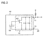
- Fig. 2 shows a circuit configuration of an analog microphone. Contained in a capsule 102 are an acoustic-electric converter 100' and an electronic circuit 110. The acoustic-electric converter 100' is formed by the capsule 102 and internal components.
- the electronic circuit 110 consists of a field-effect transistor (FET) and a capacitor, for example.
- FET field-effect transistor
- the microphone 100 has two terminals: an output terminal and a ground terminal.
- the terminal electrode (ground) 115 is shown in two positions in Fig. 1 because Fig. 1 is a cross-sectional view of a toroidal terminal.
- Fig. 3 is a cross-sectional view of an exemplary electret condenser microphone outputting a digital signal proposed by the present applicant.
- the front type electret condenser microphone 200 has an electret polymer film made of a heat-resistant material within an electrically conductive capsule 201.
- An electrically conductive diaphragm 207, an electrically conductive ring 208, a gate ring 209, and a wiring substrate 202 are provided and are separated from the electret polymer film by a spacer 206 made of an heat-resistant insulator.
- the end of the electrically conductive capsule 201 is caulked to the wiring substrate 202 and fixes the internal components.
- An IC device 210 is mounted on the interior side of the wiring substrate 202.
- Four terminals 204 (a-d) are provided on the exterior side of the wiring substrate 202.
- the terminals 204 (a-d) are protruded through an opening 223 of the front type electret condenser microphone 200 for conduction of electricity with an external object.
- Fig. 4 shows a circuit configuration of a digital microphone.
- an acoustic-electric converter 200' and an IC device 210.
- the acoustic-electric converter 200' is formed by the capsule 201 and internal components.
- the IC device 210 includes an impedance converter/amplifier 210a and a digital sigma modulator 210b.
- four terminals, a power supply terminal 204a, a clock input terminal 204b, a digital data output terminal 204c, and a ground terminal 204d, are provided.
- a problem with this digital microphone is that it is susceptible to high-frequency noise from nearby components because its ground terminal does not have a toroidal shape.
- An approach to reducing the number of components of both analog and digital microphones may be to solder the bottom of the capsule directly to a wiring board, thereby omitting the ground terminal.
- a ground electrode can be formed into a toroidal shape, the microphone would be less susceptible to high-frequency noise.
- some measures must be taken against heat transferred to the interior of the microphone during soldering in a reflow furnace.
- the vibration pickup problem cannot be solved by using the bottom itself as the ground electrode.
- An object of the present invention is to provide a structure that achieves the following four objects at the same time:
- An electro-acoustic transducer (such as a microphone) according to the present invention includes: an electrically conductive capsule having an opening for electrically connecting internal circuitry to an external object; terminals which protrude from the opening to the outside; and a raised part which is a portion of the capsule on the opening side and is spaced with a gap from the internal structure of the capsule.
- the raised part and the terminals are arranged in such a manner that the raised part and all of the terminals are able to be directly soldered to a wiring board.
- the raised part may extend toward the terminals in such a manner that the opening is narrowed.
- the raised part may have a slit extending to the boundary between the raised part and the other part of the capsule.
- the present invention there is a gap between the raised part to be soldered to a wiring board and the main structure of the electro-acoustic transducer (such as a microphone).
- the gap makes the transducer resistive to vibration.
- a ground electrode of the present invention may be toroidal so that it is not affected by any high-frequency noise.
- the number of components of the transducer can be reduced because the capsule itself functions as a ground electrode.
- the gap between the raised part and the main structure of the electro-acoustic transducer makes the transducer resistive to heat generated during soldering in a reflow furnace.
- Fig. 5 is a cross-sectional view showing a structure of a microphone according to a fist embodiment.
- An electrically conductive capsule 2 has, on the bottom face, a bottom 21 with which internal components are in contact, an opening 23 through which a terminal electrode is exposed, and raised parts 21b raised from the bottom 21.
- the capsule 2 may be made of albata or aluminum.
- a built-in substrate 112 is in contact with the bottom 21.
- the built-in substrate 112 has a ground electrode pattern 114 electrically connected to the bottom 21, and a conductor pattern 109 provided on the side opposite to the bottom 21.
- a terminal electrode (output) 11 for providing electrical contact with an external object through an opening 23 is provided on the surface of the built-in substrate 112 on the bottom 21 side.
- An electronic circuit 110 is mounted on the surface of the built-in substrate 112 on the side opposite to the bottom 21.
- the terminal electrode 11 may be formed as an integral part of the built-in substrate 112 or may be formed by plating or the like on the built-in substrate 112. Stacked on the built-in substrate 112 on the side opposite to the bottom 21 are a gate ring 108, a holder 107, a back electrode 106, a spacer 105, a diaphragm 104, a diaphragm ring 103, and a top plate 130 having sound apertures 131. The end of the capsule 2 is caulked to the top plate 130, thereby fixing the internal components.
- the lower end of the raised part 21b is substantially in the same plane as the lower end of the terminal electrode (output) 11. The purpose of this is to ensure that the terminal electrode (output) 11 and the raised part 21b are evenly soldered when the microphone is soldered to a wiring board and that the microphone is firmly mounted on the wiring board without tilting with respect to the wiring board.
- a gap of approximately 50 ⁇ m-100 ⁇ m is created between the raised part 21b and the built-in substrate 112.
- the size of the gap depends on the size of the microphone in practice. Because of the gap between the raised part 21b and the built-in substrate 112, the raised part 21b functions as a member that absorbs vibration from an external vibration source. Accordingly, vibration transferred to the microphone 1 can be reduced. Furthermore, because only the raised part 21b, rather than the entire bottom 21, is in contact with the wiring board, the contact area is reduced and therefore less vibration is transferred to the microphone 1.
- the gap can prevent heat conduction to the interior of the microphone even when the portion (raised part 21b) to be soldered is exposed to a high temperature, for example 260°C, in a reflow furnace.
- a high temperature for example 260°C
- the raised part 21b is reduced in length in the radial direction, heat transferred from the raised part 21b to the built-in substrate 112 can also be reduced because the area in contact with solder (heated area) is reduced.
- the need for the terminal electrode (ground) 115 shown in Fig. 1 can be eliminated because the raised part 21 b functions as a ground electrode.
- the raised part 2 1 b can be formed into a toroidal shape, thereby resolving the high-frequency noise problem.
- Figs. 6 and 7 are perspective views of the microphone 1 shown in Fig. 5, viewed from the bottom 21. While both Figs. 6 and 7 show examples in which the raised part 21b is split into three, the raised part 21b may be split into any other number of sections. The difference between the examples in Figs. 6 and 7 lies in the width of the slit 24.
- the elasticity of the raised part 21b can be controlled by adjusting the width of the raised part 21b. That is, the ability of the raised part 21b to absorb vibration can be controlled by adjusting the number of sections into which the raised part 21b is split and by adjusting the width of the slit 24. Heat conduction can also be controlled by adjusting the width of the raised part 21b.
- the raised part 21b which also functions as a ground electrode would lose the shape of toroid and would become susceptible to high-frequency noise.
- the provision of the raised part 21 b allows for the effects of absorbing vibration and high-frequency noise, reducing the number of components, and preventing heat conduction.
- the number of sections of the raised part 21b, the radial length of the raised part 21b, and the width of the slit 24 should be chosen to be appropriate to the environment in which the microphone 1 is used because the effects of absorbing vibration and high-frequency noise and preventing heat conduction can be in a trade-off relationship with one another.
- the position of the terminal electrode (output) 11 does not change even if the microphone is rotated because the electrode 11 is positioned in the center of the built-in substrate 112 and the raised part 21 b is provided around it in toroidal form. Therefore, when mounting the microphone, the microphone can be positioned in place merely by aligning the terminal electrode (output) 11. Furthermore, the slit 24 dividing the raised part 21b extends to the boundary 21c between the raised part 21 b and a marginal portion 21 a. Accordingly, the opening is not completely sealed when the microphone is soldered on a wiring board. That is, the slit 24 at the boundary 21 c let the gas escape during soldering. The slit 24 must have a sufficient width for releasing gas.
- Fig. 8 is a cross-sectional view of a digital front type electret condenser microphone to which the present invention is applied.
- the differences of the microphone in Fig. 8 from that in Fig. 3 lie in the shape of the electrically conductive capsule and the number of the terminals 204.
- the electrically conductive capsule 41 of the present invention has a raised part 41c on the opening 42 side. Accordingly, a caulked part 43 is not an end of the electrically conductive capsule 41.
- the raised part 41 c acts as a ground terminal and therefore eliminates the need for the ground terminal 204d shown in Fig. 3.
- Fig. 9 is a cross-sectional view of a digital back type electret condenser microphone to which the present invention is applied.
- the electrically conductive capsule 51 has a raised part 51c on the opening 52 side.
- a heat-resistive cylindrical synthetic-resin molded member 211 is provided on the internal sidewall of the electrically conductive capsule 51.
- Stacked inside the electrically conductive capsule 51 are a front plate 51a, an electrically conductive ring 208, an electrically conductive diaphragm 207, a spacer 206, an electret polymer film 205, a fixed electrode 212 having sound apertures 212a, a gate ring 209, and a wiring substrate 202 having an IC device 210 and terminals 204a-204c, in this order.
- Fig. 10 is a cross-sectional view of another digital back type electret condenser microphone to which the present invention is applied.
- the electrically conductive capsule 61 has a raised part 61c on the opening 62 side.
- a heat-resistive cylindrical synthetic-resin molded member 211 is provided on the internal sidewall of the electrically conductive capsule 61.
- Stacked inside the electrically conductive capsule 61 are a front plate 61 a, a dust-preventive metallic mesh 213 having pores 213b, a fixed electrode 212 having sound apertures 212a, an electret polymer film 205, a spacer 206, an electrically conductive diaphragm 207, a gate ring 209, an electrically conductive ring 208, and a wiring substrate 202 having an IC device 210 and terminals 204a-204c, in this order.
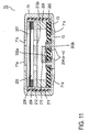
- Fig. 11 is a cross-sectional view of a digital foil type electret condenser microphone to which the present invention is applied.
- the electrically conductive capsule 71 has a raised potion 71c on the opening 72 side.
- a heat-resistive cylindrical synthetic-resin molded member 211 is provided on the internal sidewall of the electrically conductive capsule 71.
- Stacked inside the electrically conductive capsule 71 are a front plate 71 a, an electrically conductive ring 208, an electrically conductive diaphragm 207, a spacer 206, a fixed electrode 212 having sound apertures 212a, a gate ring 209, and a wiring substrate 202 having an IC device 210 and terminals 204a-204c, in this order.
- Figs. 12A, 13A, and 14A are external perspective view of digital electret condenser microphones viewed from their front-plate side.
- Fig. 12A shows a microphone with a front plate 41a, 51a, 71a having three small sound apertures 41b, 51b, 71b.
- Fig. 13A shows a microphone with a front plate 61a having a large circular sound aperture 61 b.
- Fig. 14A shows a microphone with a front plate 61 a having a large square sound aperture 61 b.
- Figs 12B, 13B, and 14B are external perspective view of the digital electret condenser microphones viewed from the opening side.
- the digital electret condenser microphones have only three terminals, a power supply terminal 204, a clock input terminal 204b, and a digital data output terminal 204c, because their raised part 41c, 51c, 61c, 71c also functions as a ground terminal.
- the raised part 41c, 51c, 71c is raised near the caulked part 43, 53, 73.
- the internal structure may be any of the structures shown in Figs. 8, 9, and 11.
- the raised part 61 c extends toward the terminals to narrow the opening 62.
- the internal structure is as shown in Fig. 10. Microphones having the structures shown in Figs.
- FIG. 8 9, and 11 also can be modified to have any of the exterior appearances shown in Figs. 13A and 14A by attaching a metallic mesh 213 on the front plate 41a, 51a, 71a. While the front plate of the three microphones is generally square, it may be a circle as shown in Figs. 6 and 7.
- the height of the raised parts 41c, 51c, 61c, 71c is substantially the same as the height of the protruded portion of the terminals 204a-204c. The purpose of this is to ensure that the terminals 204a-204c and the raised part 41c, 51c, 61c, 71c are evenly soldered when the microphone is soldered to a wiring board and that the microphone is firmly mounted on the wiring board without tilting with respect to the wiring board.
- a gap of approximately 50 ⁇ m-100 ⁇ m is created between the raised part 41c, 51c, 61c, 71c and the wiring substrate 202.
- the size of the gap depends on the size of the microphone in practice. Because of the gap, the raised part 41c, 51c, 61c, 71c functions as a member that absorbs vibration from an external vibration source. Accordingly, vibration transferred to the electret condenser microphone 40, 50, 60, 70 can be reduced.
- the gap can prevent heat conduction to the interior of the microphone even when the portion (raised part 41c, 51c, 61c, 71c) to be soldered is exposed to a high temperature, for example 260°C, in a reflow furnace.
- the elasticity and heat conduction of the raised part can be controlled by adjusting the width of the raised part 41c, 51c, 61c, 71c.
- the width of the raised part 41c, 51c, 61c, 71c is too small, the raised part would no longer surround the terminals and the microphone would become susceptible to high-frequency noise.
- the provision of the raised part 41c, 51c, 61c, 71c allows for the effects of absorbing vibration and high-frequency noise, reducing the number of components, and preventing heat conduction.
- the width of the raised part 41c, 51c, 61c, 71c and the length of its extension toward the terminals should be chosen to be appropriate to the environment in which the microphone is used because the effects of absorbing vibration and high-frequency noise and preventing heat conduction can be in a trade-off relationship with one another.
Landscapes
- Physics & Mathematics (AREA)
- Engineering & Computer Science (AREA)
- Acoustics & Sound (AREA)
- Signal Processing (AREA)
- Electrostatic, Electromagnetic, Magneto- Strictive, And Variable-Resistance Transducers (AREA)
- Details Of Audible-Bandwidth Transducers (AREA)
Applications Claiming Priority (2)
| Application Number | Priority Date | Filing Date | Title |
|---|---|---|---|
| JP2005179168 | 2005-06-20 | ||
| JP2006144089A JP4150407B2 (ja) | 2005-06-20 | 2006-05-24 | 電気音響変換器 |
Publications (3)
| Publication Number | Publication Date |
|---|---|
| EP1748676A2 true EP1748676A2 (fr) | 2007-01-31 |
| EP1748676A3 EP1748676A3 (fr) | 2007-11-07 |
| EP1748676B1 EP1748676B1 (fr) | 2008-10-29 |
Family
ID=37527046
Family Applications (1)
| Application Number | Title | Priority Date | Filing Date |
|---|---|---|---|
| EP06012395A Not-in-force EP1748676B1 (fr) | 2005-06-20 | 2006-06-16 | Transducteur électro-acoustique |
Country Status (7)
| Country | Link |
|---|---|
| US (1) | US7907743B2 (fr) |
| EP (1) | EP1748676B1 (fr) |
| JP (1) | JP4150407B2 (fr) |
| KR (1) | KR101155971B1 (fr) |
| CN (1) | CN1886000B (fr) |
| DE (1) | DE602006003378D1 (fr) |
| TW (1) | TWI381749B (fr) |
Cited By (5)
| Publication number | Priority date | Publication date | Assignee | Title |
|---|---|---|---|---|
| EP1921891A3 (fr) * | 2006-11-10 | 2009-03-04 | Hosiden Corporation | Microphone et structure de microphone |
| US7907743B2 (en) | 2005-06-20 | 2011-03-15 | Hosiden Corporation | Electro-acoustic transducer |
| EP2461605A1 (fr) * | 2010-12-06 | 2012-06-06 | Research In Motion Limited | Circuit de microphone différentiel |
| US8750537B2 (en) | 2010-12-06 | 2014-06-10 | Blackberry Limited | Differential microphone circuit |
| EP2727740B2 (fr) † | 2008-07-03 | 2018-08-08 | Hülsta-Werke Hüls GmbH & Co. KG | Procédé de fabrication d'éléments plats et papier d'impression imprimé avec un décor. |
Families Citing this family (25)
| Publication number | Priority date | Publication date | Assignee | Title |
|---|---|---|---|---|
| KR100797440B1 (ko) * | 2006-09-05 | 2008-01-23 | 주식회사 비에스이 | 사각통 형상의 일렉트릿 콘덴서 마이크로폰 |
| CN101606397A (zh) * | 2006-12-15 | 2009-12-16 | 加利福尼亚大学董事会 | 声学基片 |
| JP4939922B2 (ja) * | 2006-12-27 | 2012-05-30 | 株式会社オーディオテクニカ | コンデンサマイクロホン |
| JP2009005253A (ja) * | 2007-06-25 | 2009-01-08 | Hosiden Corp | コンデンサマイクロホン |
| KR20090039376A (ko) * | 2007-10-18 | 2009-04-22 | 주식회사 비에스이 | 기생용량을 줄인 콘덴서 마이크로폰 조립체 |
| KR100982239B1 (ko) * | 2007-11-02 | 2010-09-14 | 주식회사 비에스이 | 피시비에 음공이 형성된 멤스 마이크로폰 패키지 |
| JP4944760B2 (ja) * | 2007-12-27 | 2012-06-06 | ホシデン株式会社 | エレクトレットコンデンサマイクロホン |
| US8254609B2 (en) * | 2008-04-02 | 2012-08-28 | Starkey Laboratories, Inc. | Microphones sharing a common acoustic part and volume |
| JP5481852B2 (ja) * | 2008-12-12 | 2014-04-23 | 船井電機株式会社 | マイクロホンユニット及びそれを備えた音声入力装置 |
| TW201026097A (en) * | 2008-12-30 | 2010-07-01 | Ind Tech Res Inst | Solar flexpeaker structure and speaker therewith |
| US8280080B2 (en) * | 2009-04-28 | 2012-10-02 | Avago Technologies Wireless Ip (Singapore) Pte. Ltd. | Microcap acoustic transducer device |
| JP4809912B2 (ja) * | 2009-07-03 | 2011-11-09 | ホシデン株式会社 | コンデンサマイクロホン |
| CN102256199A (zh) * | 2010-10-12 | 2011-11-23 | 歌尔声学股份有限公司 | 一种微型电容式麦克风 |
| KR101303954B1 (ko) | 2012-12-14 | 2013-09-05 | 주식회사 비에스이 | 광대역 및 방수 특성을 위한 보텀 포트형 마이크로폰 조립체 |
| CN103051990B (zh) * | 2012-12-25 | 2016-08-10 | 苏州恒听电子有限公司 | 自适应送话器 |
| JP2014239203A (ja) * | 2014-01-31 | 2014-12-18 | 株式会社村田製作所 | 電子部品及び電子部品の実装構造体 |
| JP6319797B2 (ja) * | 2014-06-04 | 2018-05-09 | 株式会社オーディオテクニカ | コンデンサマイクロホンユニット |
| CN107197412B (zh) * | 2017-06-20 | 2020-05-29 | 瑞声科技(新加坡)有限公司 | 发声器 |
| DE102018203098B3 (de) * | 2018-03-01 | 2019-06-19 | Infineon Technologies Ag | MEMS-Sensor |
| JP7410935B2 (ja) | 2018-05-24 | 2024-01-10 | ザ リサーチ ファウンデーション フォー ザ ステイト ユニバーシティー オブ ニューヨーク | 容量性センサ |
| TWI741395B (zh) * | 2019-10-23 | 2021-10-01 | 音賜股份有限公司 | 適於pcb上安裝電聲元件的方法及電聲元件結構 |
| CN112700759B (zh) * | 2019-10-23 | 2024-12-31 | 音赐股份有限公司 | 适于pcb上安装电声元件的方法及电声元件结构 |
| CN116195270A (zh) * | 2020-09-21 | 2023-05-30 | 弗里德曼电子私人有限公司 | 驻极体胶囊 |
| TWI842114B (zh) * | 2022-09-30 | 2024-05-11 | 大陸商美律電子(深圳)有限公司 | 電子裝置 |
| TWI863020B (zh) * | 2022-11-08 | 2024-11-21 | 音賜股份有限公司 | 電聲裝置及其電路板端蓋 |
Family Cites Families (10)
| Publication number | Priority date | Publication date | Assignee | Title |
|---|---|---|---|---|
| JPH02149199A (ja) * | 1988-11-30 | 1990-06-07 | Matsushita Electric Ind Co Ltd | エレクトレットコンデンサマイクロホン |
| US5272758A (en) * | 1991-09-09 | 1993-12-21 | Hosiden Corporation | Electret condenser microphone unit |
| JP2002191087A (ja) | 2000-12-22 | 2002-07-05 | Primo Co Ltd | 電気音響変換ユニット及び電子機器 |
| AT409695B (de) * | 2001-05-18 | 2002-10-25 | Akg Acoustics Gmbh | Elektrostatisches mikrofon |
| KR100420128B1 (ko) * | 2001-05-22 | 2004-03-02 | 주식회사 비에스이 | 일렉트렛 콘덴서 마이크로폰 |
| JP4127469B2 (ja) | 2001-11-16 | 2008-07-30 | 株式会社プリモ | エレクトレットコンデンサマイクロホン |
| JP3916997B2 (ja) * | 2002-04-30 | 2007-05-23 | スター精密株式会社 | 電気音響変換器 |
| KR200332944Y1 (ko) * | 2003-07-29 | 2003-11-14 | 주식회사 비에스이 | Smd가능한 일렉트렛 콘덴서 마이크로폰 |
| KR100531716B1 (ko) | 2003-12-04 | 2005-11-30 | 주식회사 비에스이 | Smd용 콘덴서 마이크로폰 |
| JP4150407B2 (ja) | 2005-06-20 | 2008-09-17 | ホシデン株式会社 | 電気音響変換器 |
-
2006
- 2006-05-24 JP JP2006144089A patent/JP4150407B2/ja not_active Expired - Fee Related
- 2006-06-08 US US11/449,908 patent/US7907743B2/en not_active Expired - Fee Related
- 2006-06-14 TW TW095121274A patent/TWI381749B/zh not_active IP Right Cessation
- 2006-06-14 KR KR1020060053358A patent/KR101155971B1/ko not_active Expired - Fee Related
- 2006-06-16 EP EP06012395A patent/EP1748676B1/fr not_active Not-in-force
- 2006-06-16 DE DE602006003378T patent/DE602006003378D1/de active Active
- 2006-06-20 CN CN2006100938493A patent/CN1886000B/zh not_active Expired - Fee Related
Cited By (6)
| Publication number | Priority date | Publication date | Assignee | Title |
|---|---|---|---|---|
| US7907743B2 (en) | 2005-06-20 | 2011-03-15 | Hosiden Corporation | Electro-acoustic transducer |
| EP1921891A3 (fr) * | 2006-11-10 | 2009-03-04 | Hosiden Corporation | Microphone et structure de microphone |
| US8050443B2 (en) | 2006-11-10 | 2011-11-01 | Hosiden Corporation | Microphone and microphone mounting structure |
| EP2727740B2 (fr) † | 2008-07-03 | 2018-08-08 | Hülsta-Werke Hüls GmbH & Co. KG | Procédé de fabrication d'éléments plats et papier d'impression imprimé avec un décor. |
| EP2461605A1 (fr) * | 2010-12-06 | 2012-06-06 | Research In Motion Limited | Circuit de microphone différentiel |
| US8750537B2 (en) | 2010-12-06 | 2014-06-10 | Blackberry Limited | Differential microphone circuit |
Also Published As
| Publication number | Publication date |
|---|---|
| CN1886000A (zh) | 2006-12-27 |
| EP1748676B1 (fr) | 2008-10-29 |
| DE602006003378D1 (de) | 2008-12-11 |
| TWI381749B (zh) | 2013-01-01 |
| EP1748676A3 (fr) | 2007-11-07 |
| CN1886000B (zh) | 2011-08-03 |
| JP2007037096A (ja) | 2007-02-08 |
| KR101155971B1 (ko) | 2012-06-18 |
| JP4150407B2 (ja) | 2008-09-17 |
| KR20060133459A (ko) | 2006-12-26 |
| TW200715894A (en) | 2007-04-16 |
| US7907743B2 (en) | 2011-03-15 |
| US20060285707A1 (en) | 2006-12-21 |
Similar Documents
| Publication | Publication Date | Title |
|---|---|---|
| EP1748676B1 (fr) | Transducteur électro-acoustique | |
| KR100673849B1 (ko) | 메인보드에 실장되는 콘덴서 마이크로폰 및 이를 포함하는이동통신 단말기 | |
| US6904155B2 (en) | Electret capacitor microphone | |
| EP1691570A2 (fr) | Microphone | |
| US9271435B2 (en) | Miniature microphone, protection frame thereof and method for manufacturing the same | |
| JP2006174005A (ja) | コンデンサマイクロホンとその製造方法 | |
| KR20080023144A (ko) | 휴대용 전자 기기에 적합한 마이크 모듈 및 장착 구조물 | |
| CN1706216B (zh) | 平行六面体型电容式传声器 | |
| KR100845670B1 (ko) | 일렉트릿 콘덴서 마이크로폰 | |
| CN1706218B (zh) | 可安装在主pcb上的电容式传声器 | |
| US7697707B2 (en) | Capacitor microphone unit | |
| US8408941B2 (en) | Condenser microphone and its output connector | |
| US7344405B2 (en) | Electro-acoustic transducer with holder | |
| US8150078B2 (en) | Electret condenser microphone | |
| CN107493361B (zh) | 耳机座防水组件及移动终端 | |
| WO2009097822A1 (fr) | Socle de montage et composant électronique l'utilisant | |
| CN107732555B (zh) | 耳机座防水组件及移动终端 | |
| KR100406256B1 (ko) | 전기적 접촉을 위한 돌출부를 갖는 인쇄회로기판을 포함한마이크로폰 및 그의 연결 방법 | |
| JP6017930B2 (ja) | マイクおよびその実装構造 | |
| US20070235502A1 (en) | Condenser Microphone | |
| JPH10224894A (ja) | 圧電音響装置 | |
| JP2002335061A (ja) | 電気音響部品用ホルダ | |
| JP2006060373A (ja) | コンデンサマイクロホン | |
| JP2003037884A (ja) | マイクロホンホルダ | |
| JP2004031538A (ja) | 電磁シールド構造 |
Legal Events
| Date | Code | Title | Description |
|---|---|---|---|
| PUAI | Public reference made under article 153(3) epc to a published international application that has entered the european phase |
Free format text: ORIGINAL CODE: 0009012 |
|
| AK | Designated contracting states |
Kind code of ref document: A2 Designated state(s): AT BE BG CH CY CZ DE DK EE ES FI FR GB GR HU IE IS IT LI LT LU LV MC NL PL PT RO SE SI SK TR |
|
| AX | Request for extension of the european patent |
Extension state: AL BA HR MK YU |
|
| PUAL | Search report despatched |
Free format text: ORIGINAL CODE: 0009013 |
|
| AK | Designated contracting states |
Kind code of ref document: A3 Designated state(s): AT BE BG CH CY CZ DE DK EE ES FI FR GB GR HU IE IS IT LI LT LU LV MC NL PL PT RO SE SI SK TR |
|
| AX | Request for extension of the european patent |
Extension state: AL BA HR MK YU |
|
| 17P | Request for examination filed |
Effective date: 20071012 |
|
| GRAP | Despatch of communication of intention to grant a patent |
Free format text: ORIGINAL CODE: EPIDOSNIGR1 |
|
| AKX | Designation fees paid |
Designated state(s): DE FI FR SE |
|
| GRAS | Grant fee paid |
Free format text: ORIGINAL CODE: EPIDOSNIGR3 |
|
| GRAA | (expected) grant |
Free format text: ORIGINAL CODE: 0009210 |
|
| AK | Designated contracting states |
Kind code of ref document: B1 Designated state(s): DE FI FR SE |
|
| REF | Corresponds to: |
Ref document number: 602006003378 Country of ref document: DE Date of ref document: 20081211 Kind code of ref document: P |
|
| REG | Reference to a national code |
Ref country code: SE Ref legal event code: TRGR |
|
| PLBE | No opposition filed within time limit |
Free format text: ORIGINAL CODE: 0009261 |
|
| STAA | Information on the status of an ep patent application or granted ep patent |
Free format text: STATUS: NO OPPOSITION FILED WITHIN TIME LIMIT |
|
| 26N | No opposition filed |
Effective date: 20090730 |
|
| PGFP | Annual fee paid to national office [announced via postgrant information from national office to epo] |
Ref country code: DE Payment date: 20140630 Year of fee payment: 9 Ref country code: FR Payment date: 20140409 Year of fee payment: 9 Ref country code: SE Payment date: 20140611 Year of fee payment: 9 Ref country code: FI Payment date: 20140410 Year of fee payment: 9 |
|
| REG | Reference to a national code |
Ref country code: DE Ref legal event code: R119 Ref document number: 602006003378 Country of ref document: DE |
|
| PG25 | Lapsed in a contracting state [announced via postgrant information from national office to epo] |
Ref country code: FI Free format text: LAPSE BECAUSE OF NON-PAYMENT OF DUE FEES Effective date: 20150616 |
|
| REG | Reference to a national code |
Ref country code: SE Ref legal event code: EUG |
|
| PG25 | Lapsed in a contracting state [announced via postgrant information from national office to epo] |
Ref country code: SE Free format text: LAPSE BECAUSE OF NON-PAYMENT OF DUE FEES Effective date: 20150617 |
|
| REG | Reference to a national code |
Ref country code: FR Ref legal event code: ST Effective date: 20160229 |
|
| PG25 | Lapsed in a contracting state [announced via postgrant information from national office to epo] |
Ref country code: DE Free format text: LAPSE BECAUSE OF NON-PAYMENT OF DUE FEES Effective date: 20160101 |
|
| PG25 | Lapsed in a contracting state [announced via postgrant information from national office to epo] |
Ref country code: FR Free format text: LAPSE BECAUSE OF NON-PAYMENT OF DUE FEES Effective date: 20150630 |