EP1749219B1 - Laserradarvorrichtung und verfahren - Google Patents
Laserradarvorrichtung und verfahren Download PDFInfo
- Publication number
- EP1749219B1 EP1749219B1 EP05744679A EP05744679A EP1749219B1 EP 1749219 B1 EP1749219 B1 EP 1749219B1 EP 05744679 A EP05744679 A EP 05744679A EP 05744679 A EP05744679 A EP 05744679A EP 1749219 B1 EP1749219 B1 EP 1749219B1
- Authority
- EP
- European Patent Office
- Prior art keywords
- remote probe
- doppler
- probe volume
- wind
- scatter
- Prior art date
- Legal status (The legal status is an assumption and is not a legal conclusion. Google has not performed a legal analysis and makes no representation as to the accuracy of the status listed.)
- Expired - Lifetime
Links
Images



Classifications
-
- G—PHYSICS
- G01—MEASURING; TESTING
- G01S—RADIO DIRECTION-FINDING; RADIO NAVIGATION; DETERMINING DISTANCE OR VELOCITY BY USE OF RADIO WAVES; LOCATING OR PRESENCE-DETECTING BY USE OF THE REFLECTION OR RERADIATION OF RADIO WAVES; ANALOGOUS ARRANGEMENTS USING OTHER WAVES
- G01S17/00—Systems using the reflection or reradiation of electromagnetic waves other than radio waves, e.g. lidar systems
- G01S17/88—Lidar systems specially adapted for specific applications
- G01S17/95—Lidar systems specially adapted for specific applications for meteorological use
-
- G—PHYSICS
- G01—MEASURING; TESTING
- G01S—RADIO DIRECTION-FINDING; RADIO NAVIGATION; DETERMINING DISTANCE OR VELOCITY BY USE OF RADIO WAVES; LOCATING OR PRESENCE-DETECTING BY USE OF THE REFLECTION OR RERADIATION OF RADIO WAVES; ANALOGOUS ARRANGEMENTS USING OTHER WAVES
- G01S7/00—Details of systems according to groups G01S13/00, G01S15/00, G01S17/00
- G01S7/48—Details of systems according to groups G01S13/00, G01S15/00, G01S17/00 of systems according to group G01S17/00
- G01S7/491—Details of non-pulse systems
- G01S7/493—Extracting wanted echo signals
-
- Y—GENERAL TAGGING OF NEW TECHNOLOGICAL DEVELOPMENTS; GENERAL TAGGING OF CROSS-SECTIONAL TECHNOLOGIES SPANNING OVER SEVERAL SECTIONS OF THE IPC; TECHNICAL SUBJECTS COVERED BY FORMER USPC CROSS-REFERENCE ART COLLECTIONS [XRACs] AND DIGESTS
- Y02—TECHNOLOGIES OR APPLICATIONS FOR MITIGATION OR ADAPTATION AGAINST CLIMATE CHANGE
- Y02A—TECHNOLOGIES FOR ADAPTATION TO CLIMATE CHANGE
- Y02A90/00—Technologies having an indirect contribution to adaptation to climate change
- Y02A90/10—Information and communication technologies [ICT] supporting adaptation to climate change, e.g. for weather forecasting or climate simulation
Definitions
- the present invention relates to coherent laser radar (lidar) devices and a method for operating such devices.
- Lidars are well known and have been used to measure wind profiles for many years.
- the basic principle of a lidar device is to direct a laser beam to a point or region in space and to detect the returned signal.
- Measurement of the Doppler shifted light back-scattered by small natural particles and droplets (aerosols) present in the atmosphere is used to provide a measure of the line of sight wind speed. If the laser beam is scanned, multiple wind velocity components can be determined allowing more information on the wind vector to be calculated.
- optical fibre based lidar An example of an early, carbon dioxide laser based, lidar is described in Vaughan, J M et al: "Laser Doppler velocimetry applied to the measurement of local and global wind", Wind engineering, Vol. 13, no. 1, 1989 . More recently, optical fibre based lidar systems have also been developed; for example, see Karlsson et al, Applied Optics, Vol. 39, No. 21, 20 July 2000 and Harris et al, Applied Optics, Vol. 40, pp 1501-1506 (2001 ). Optical fibre based systems offer numerous advantages over traditional gas laser based systems. For example, optical fibre based systems are relatively compact and can be fabricated using standard telecommunication components which are moderately priced and typically very reliable.
- optical fibre based lidars have the potential to replace the traditional cup anemometer, this will only occur if and when it can be ensured that the data acquired over prolonged periods of time is at least as reliable as that produced by known mechanical systems.
- concerns over the long term reliability of wind speed data acquired using lidar based anemometers has hindered their uptake as replacements for traditional mechanical cup anemometers based systems.
- US 4735503 discloses a method for determining the speed of the wind by means of a laser Doppler anemometer and a multiple peak finding algorithm.
- a coherent laser radar device for atmospheric wind speed measurement comprises a transmitted for focussing a beam of light to a remote probe volumes the transmitter having a variable focus mechanism and being arranged to sequentially focus light to a plurality of remote probe volumes, comprising at least one measurement remote probe volume and at least one reference remote probe volume, a receiver for detecting back-scattered light, and an analyser for calculating wind speed at the, or each, measurement remote probe volume from the Doppler shift in frequency of the detected back-scattered light, characterised in that the analyser is arranged to produce Doppler spectra comprising the intensity of the detected back-scattered light as a function of Doppler shift frequency for each measurement at each of said measurements and reference remote probe volumes and to use at least one Doppler spectrum produced for a reference remote probe volume to correct the or each Doppler spectrum produced for a measurement probe volume for any Doppler frequency components of the detected back-scattered light that arise from back-scatter off cloud located at a range
- prior art coherent laser radar devices are inherently reliable in the sense that they comprise optical transmitters that will accurately and reliably transmit a beam of light in a known direction and receivers that can consistently detect back-scattered light from a known direction with a substantially invariant sensitivity. In ideal conditions, prior art coherent laser radar devices are thus capable of acquiring highly accurate wind speed information for a remote probe volume of interest. However, it has been found that under certain atmospheric conditions significant errors are associated with the wind velocity values calculated by such prior art coherent laser radar device.
- the detected back-scattered signal can be dominated, or at least comprise a significant component, that does not actually arise from reflections off aerosols in the probe volume of interest but is due to reflections from the higher density of aerosols (water droplets) found in cloud.
- prior art coherent laser radar devices provide a "false" wind speed reading that is not truly indicative of the wind velocity in the remote probe volume because of the effect of the cloud returns.
- the present invention thus provides a lidar device in which an analyser is provided that is arranged to monitor for the presence of, and to ensure the calculated wind speed is corrected for, any Doppler frequency components of detected back-scattered light that arise from back-scatter off cloud located at a range greater than the range of the remote probe volume (i.e. for light reflected from aerosols outside of the remote probe volume).
- a device of the present invention thus has a reduced susceptibility to false readings due to cloud, and may provide an indication that the calculated wind velocity values have been affected by a cloud return signal and are likely to have a certain level of uncertainty associated therewith.
- a device of the present invention thus ensures the operator has greater confidence in the wind velocity values calculated by the lidar.
- the indication may be in the form of an error output associated with each calculated velocity value or it may be that only velocity values having a certain confidence level associated therewith are output or recorded by the lidar.
- the device comprises means for providing an indication of the confidence associated with calculated wind velocities.
- the present invention thus provides a lidar device that, unlike prior art systems, is capable of making reliable long term, unattended, wind velocity measurements even in the presence of an intermittent and/or varying cloud base.
- the back-scattered light detected by the receiver provides a measure of the "line of sight" wind velocity; i.e. the returned light is Doppler shifted by an amount related to the velocity components of aerosols parallel to the transmit/receive beam direction.
- different wind velocity component can advantageously be determined by providing scanning means to scan the beam of light transmitted by the transmitter and the receive beam defined by the receiver within the remote probe volume. Scanning the lidar in this manner enables the wind vector within the remote probe volume to be intersected at a number of known angles thereby allowing the true wind velocity vector to be constructed and thus enabling various velocity components to be measured.
- the implementation of a scanned lidar device in accordance with the present invention is described in more detail below.
- the term "receive beam” is well known to those skilled in the art and is used to denote the direction from which any returned light will be collected by the receiver optics and passed to the detector. In other words the receive beam is not a beam of photons, but simply a pseudo or virtual beam that defines a volume in space from which back-scattered light can be detected.
- the term "remote probe volume” is used to define the 3D region in space from which wind velocity data is required. In the case of a non-scanned beam, the remote probe volume will be defined by the transmit/receive beam overlap and/or focus, whilst for a scanned device the remote probe volume will additionally be defined by the scan pattern. For example, in the case of a conical scan the remote probe volume will be a disc of air having a radius defined by the scan angle and a thickness defined by the depth of focus of the transmit/receive beams.
- the transmitter comprises a variable focus mechanism thereby enabling the range of the remote probe volume to be varied as required.
- the receiver may also have a variable focus mechanism.
- the device is arranged such that, during use, the focus of the receive beam is arranged to coincide with the focus of the transmit beam.
- the transmit beam output by the transmitter and the receive beam defined by the receiver may thus both have a variable focal distance which, in the case of an upwardly directed device, allows the height (i.e. altitude) of the remote probe volume from the ground to be varied as required.
- the variable focus mechanism may be arranged to provide a continuously variable focus, or it may be arranged to provide any one of a plurality of focus conditions.
- the device is arranged to sequentially measure wind speed at a plurality of measurement remote probe volumes, wherein each of said plurality of measurement remote probe volumes is at range less than a first range limit.
- the term "measurement remote probe volume" refers to a probe volume in which wind speed data is required; i.e. it a probe volume of interest.
- the measurement remote probe volumes may be located at any number of heights of interest.
- the first set of measurements may be at the height of proposed or actual wind turbine blades, say, 50m, 100m and 150m above ground level.
- the device may also or alternatively be arranged to measure, in parallel, wind speed at a plurality of measurement remote probe volumes, wherein each of said plurality of measurement remote probe volumes is at range less than a first range limit.
- the transmitter is additionally arranged to focus the beam of light to at least one reference remote probe volume, said at least one reference remote probe volume being at a range greater than said first range limit.
- reference remote probe volume refers to a probe volume in which wind speed data may not be required but from which a cloud return signal can be collected if cloud is present.
- the reference remote probe volume(s) is typically located at a height at which the presence of a cloud return would produce a measurable return signal for measurements made at the measurement remote probe volumes.
- the reference remote probe volume may be located 300m above ground level. It should be noted that, if required, a wind velocity could be calculated for the reference remote probe volume; for example, the measurement could be used to provide a measure of cloud velocity.
- the Doppler frequency characteristics of the back-scattered light detected when the transmitter is focussed to said at least one reference remote probe volume are used by the analyser during the calculation of wind speed at each of said plurality of measurement remote probe volumes.
- the analyser may be advantageously arranged to produce Doppler spectra comprising the intensity of the detected back-scattered light as a function of Doppler shift frequency for each measurement at each of said measurement and reference remote probe volumes, wherein the calculation of wind speed comprises subtracting at least one reference Doppler spectrum from each of the measurement Doppler spectra.
- the device may be arranged to continuously acquire wind speed data. Doppler spectra may thus be acquired at each measurement remote probe volume in turn followed by, or preceded by, a measurement at the reference remote probe volume(s). This acquisition cycle may then be repeated for as long as required. It should also be noted that data may be acquired from the remote probe volumes in any order, although acquiring data for sequentially increasing range reduces the magnitude of focus adjustment required between measurements.
- a plurality of lidar devices, or a wavelength multiplexed lidar may alternatively or additionally be used to take a plurality of measurements at different heights in parallel.
- the device may be arranged to take a number of measurements in each probe volume (e.g. it may comprise conically scanned beam) as described in more detail below.
- a device in which the wind speed calculated at each remote probe volume of said first set is substantially unaffected by any Doppler frequency components of the detected back-scattered light that arise from back-scatter off cloud located at a range greater than the first range limit.
- Doppler spectra acquired for ranges greater than the range limit are used by the analyser to correct the wind speed determined from the Doppler spectra at a range less than the first range limit.
- the first range limit would typically be less than the range to the typical atmospheric cloud base for the region of measurement. It should also be emphasised that the first range limit does not refer to the maximum instrumented range of the device but to the limit of the range of interest for measurements.
- the analyser may advantageously be arranged to monitor the intensity of the detected back-scattered light as a function of Doppler shift frequency for the presence of two or more discrete intensity peaks; i.e. for peaks that occur at different Doppler frequencies.
- the device additionally comprises an atmospheric back-scatter profiling means (e.g. an atmospheric back-scatter profiler) for measuring the back-scatter cross-section of the atmosphere as a function of range.
- an atmospheric back-scatter profiling means e.g. an atmospheric back-scatter profiler
- a coherent laser radar device may be provided that includes a wind Doppler lidar and an atmospheric back scatter profiler.
- the atmospheric back-scatter prowler is preferably a pulsed laser radar device which allows back-scatter to be accurately measured as a function of range.
- the output beam of the atmospheric back-scatter profiler is preferable directed along the same path, or a substantially similar path, as the beam of light transmitted by the transmitter.
- back-scatter profiling means ensures that, for an upwardly pointing lidar system, any error introduced by the presence of a low cloud base can be monitored.
- back-scattered signals detected by the receiver of an upwardly pointing lidar can be dominated, in the presence of a low cloud base, by back-scatter from the highly scattering cloud rather than by the back-scatter from aerosols in the remote probe volume. This occurs because although the lidar has the greatest sensitivity to light back-scattered from the remote probe volume, it still has some sensitivity to light returned from outside of the remote probe volume.
- a lidar incorporating a back-scatter profiling means thus significantly reduces the possibility of making "false" wind speed measurements, and provides a more robust and reliable system suitable for making long term, unattended, measurements.
- the atmospheric back-scatter profiling means comprises a ceilometer.
- Ceilometers are known pulsed lidar devices, and have been used for many years to measure cloud height in the vicinity of airports and the like. Although the provision of a separate pulsed lidar is preferred for simplicity and to enable simultaneous back-scatter profile and wind speed measurements, the skilled person would appreciate that it would also be possible to adapt the coherent laser radar that provides the wind speed measurements to additionally operate in a pulsed mode to measure the back-scatter profile.
- the atmospheric back-scatter profiler may comprise means for determining the power of the detected back-scattered light as a function of the distance of the remote probe volume from the device.
- the optical power of the back-scattered light collected by the receiver may be used as an indication of the scattering strength at a particular height.
- the returned power as a function of remote probe volume range can then provide a backscatter profile.
- the distance of the remote probe volume from the device can be readily controlled by varying, for example, its focus.
- the analyser is arranged to take the back-scatter profile measured by the atmospheric back-scatter profiler and to use said back-scatter profile to ensure the calculated wind speed is corrected for any Doppler frequency components of the detected back-scattered light that arise from back-scatter off cloud located at a range greater than the range of the remote probe volume (i.e. to provide an indication of whether the calculated wind velocity is characteristic of the wind velocity at the remote probe volume).
- the atmospheric back-scatter profiling means provides a profile of the back-scattering cross-section as a function of range.
- This back-scatter/range profile is then used, in combination with the known or previously measured sensitivity properties of the coherent laser radar, to determine the proportion of the back-scattered light collected by the receiver that arises from back-scatter off aerosols in the remote probe volume. It is then possible for the device to provide an indication of whether the calculated wind velocity is likely to be characteristic of the true wind velocity at the remote probe volume. In many cases, a simple "0" (invalid reading- cloud signal dominates) or "1" (valid reading - aerosol signal dominates) is sufficient. Alternatively, a more detailed measure of the uncertainty associated with calculated velocity could be calculated.
- wind velocity measurement apparatus comprises a coherent continuous wave lidar device and a non-coherent pulsed lidar device such as a ceilometer.
- An atmospheric back-scatter profile is determined by the pulsed lidar device and used, in combination with the known (e.g. predicted or measured) sensitivity of the continuous wave lidar device, to determine the region of space being probed by the continuous wave lidar device.
- the data provided by the ceilometer is thus used in a calculation that allows the proportion of back-scattered light that arises from the remote probe volume to be assessed.
- the coherent transmitted beam and the pulsed beam of the back-scatter profiling means should be similar in wavelength.
- the similar wavelengths arc required as the back-scatter properties of the atmosphere are wavelength dependent.
- a simple calibration factor can be used to convert the back-scatter properties at the wavelength of operation of the back-scatter profiling means to the wavelength of operation of the coherent beam.
- scanning means are provided to scan the beam of light transmitted by the transmitted within the remote probe volume.
- the analyser is arranged to determine a line of sight wind velocity value for a plurality of known scan positions within the remote probe volume and to calculate at least one wind velocity component at the remote probe volume by fitting the plurality of line of sight velocity values to a predetermined function.
- Doppler spectra may thus be acquired by the lidar at a plurality of known positions within the remote probe volume from which multiple line of sight velocity values are calculated.
- a plot of the line of sight velocity values versus position can be fitted to a certain predetermined mathematical function and various wind velocity component within the remote probe volume can be extracted.
- the predetermined function is a sinusoidal function and the scanning means is arranged to conically scan the beam of light transmitted by the transmitter and the receive beam defined by the receive.
- the offset i.e. the DC component
- the amplitude of the sine wave gives a measure of the horizontal velocity component whilst the phase of the sine curve provides an indication of the wind bearing component.
- the analyser may operate using any co-ordinate system; for example, the positional information may be expressed in Cartesian or polar co-ordinates as required.
- the analyser may be arranged to perform an initial fit of the plurality of line of sight velocity values to the predetermined function and to determined, from the initial fit, which of the plurality of line of sight velocity values are to be used to calculate the at least one wind velocity component at the remote probe volume.
- the analyser is arranged such that one or more line of sight velocity values acquired during the scan are omitted from the calculation of the at least one wind velocity component.
- the plurality of line of sight velocity values used to calculate the least one wind velocity component at the remote probe volume may comprise the line of sight velocity values having a deviation from the initial fit less than a predetermined amount.
- the analyser may be arranged to omit potentially spurious points (e.g. points having a deviation from the initial fit greater than a predetermined amount) from the calculation that determines the at least one velocity component. These spurious points may arise from solid objects (c.g. insects, birds, vehicles, aircraft etc) moving in the transmit/receive beam path.
- the plurality of line of sight velocity values used to calculate the at least one wind velocity component at the remote probe volume exclude the N line of sight velocity values having the highest deviation from the initial fit, wherein N is a predetermined integer greater than or equal to one and less than the number of line of sight velocity values.
- N is a predetermined integer greater than or equal to one and less than the number of line of sight velocity values.
- an initial fit of the plurality of line of sight velocity values to the predetermined function is performed and the result of the initial fit includes a measure of the deviation of each measured line of sight velocity value from the best fit curve.
- the N data points with the highest deviation from the initial fit are omitted.
- the value of N is greater than or equal to one and preferably less or significantly less than the number of acquired line of sight velocity values.
- the preferred value of N will be dictated by the environment in which the lidar is located, and may be 1, 2, 3, 4 ,5 or greater than 5, 10, 15 or 20.
- a scanned lidar system may thus be provided in which the analyser is arranged to determine the presence of any spurious line of sight velocity data points and to exclude such spurious data points when calculating wind velocity.
- fitting the plurality of line of sight velocity values to a predetermined function is performed using a least sum of squares technique.
- suitable fitting routines are commercially available; for example, NAG (National Algorithms group) routines could be employed.
- the device is monostatic.
- the receiver and transmitter share common optics that form substantially parallel and overlapping transmit and receive beams.
- the focus of the transmit and receive beams is always coincident when such a monostatic arrangement is used.
- the device could be bistatic.
- the transmitter and receiver comprise discrete and separate optical arrangement.
- a device comprising means for simultaneously altering the focus and "squint" of a bistatic arrangement is described in PCT patent application GB03/04408 .
- the back scattered light collected by the receiver is mixed with a local oscillator signal extracted from the light source of the transmitter prior to detection.
- a heterodyne detection system is provided. This allows the Doppler shift data to be readily extracted from the beat frequency of the local oscillator and returned (i.e, back-scattered) light.
- the transmitted beam of light comprises infrared radiation.
- the device could incorporate a solid state laser and may be arranged to operate at the 1.55 ⁇ m telecommunications wavelength.
- the term "light” is used to describe visible and non-visible radiation of any wavelengths from the deep ultra-violet to the far infra-red.
- the lidar may be arranged for CW or pulsed operation.
- the transmitter and receive comprise optical components linked by optical fibre.
- the device comprises at least one piece of optical fibre. Fibre based systems of this type can be fabricated using "off the shelf” optical components and are relatively cheap, robust and reliable.
- the device is arranged for ground based, upwardly directed, operation.
- the device is arranged to be pointed substantially vertically and to measure the wind velocity in a remote probe volume located a certain height above the ground.
- Ground based operation may include use of the lidar on a buoyant platform.
- a coherent laser radar device for measuring wind speed comprises a transmitter for transmitting a beam of light to a remote probe volume, a receiver for detecting back-scattered light and an analyser for calculating wind velocity at the remote probe volume from the Doppler shift in frequency of the detected back-scattered light, wherein means are provided for indicating whether, and/or for ensuring that, calculated wind velocities are characteristic of the wind velocity at the remote probe volume.
- a coherent laser radar device for atmospheric wind speed measurement comprises: a transmitter for focussing a beam of light to a remote probe volume, a receiver for detecting back-scattered light, and an analyser for calculating wind speed at the remote probe volume from the intensity of back-scattered light detected by the receiver as a function of Doppler shift frequency, wherein the analyser is arranged such that the wind speed calculation excludes any Doppler frequency components that arise due to back-scattering from aerosols (e.g. cloud) located at a range greater than the range at which the transmitted beam of light is focussed.
- aerosols e.g. cloud
- a coherent laser radar device for atmospheric wind speed measurement comprises: a transmitter for focussing a beam of light to at least a first remote probe volume located a range R from said device, a receiver for detecting back-scattered light, and an analyser for calculating wind velocity at the remote probe volume of interest from any Doppler shift in frequency of the detected back-scattered light, characterised in that an error detector is provided to determine any Doppler shift components of the detected back-scattered light that arise from scattering of light at a range greater than the range R.
- a wind turbine, or a wind farm comprising multiple wind turbines may comprise at least one coherent laser radar device of the type described herein.
- any such coherent laser radar device is arranged to measure the velocity of wind at a remote probe volume upwind of the wind turbine.
- the beam of light transmitted by the coherent laser radar device may be passed through the region of space swept by the blades of the wind turbine.
- the analyser may be arranged such that reflections from the turbine blades do not affect the calculated wind velocity measurements.
- a method for calculating atmospheric wind velocity comprise the steps of (i) taking Doppler frequency data acquired by a coherent laser radar device from a plurality of remote probe volumes and forming a first set of Doppler spectra acquired from one or more measurement remote probe volumes at a range less than a first range limit and a second set of Doppler spectra acquired from one or more remote probe volumes at a range greater than said first range limit, and (ii) calculating wind velocity at the remote probe volume of the coherent laser radar device from said Doppler frequency data, characterised in that step (ii) comprises using said second set of Doppler spectra to ensure the wind speed calculated from each of said first set of Doppler spectra is corrected for any Doppler frequency components that arise from back-scatter off cloud located at a range greater than the range of the remote probe volume.
- the step of calculating wind velocity at the remote probe volume of the coherent laser radar device from Doppler frequency data comprises providing an indication of whether, and/or
- Said Doppler frequency data comprises a plurality of Doppler spectra (i.e. received intensity as a function of Doppler frequency) acquired from a plurality of remote probe volumes.
- said plurality of Doppler spectra comprise a first set of Doppler spectra acquired from one or more measurements remote probe volumes at a range less than a first range limit and a second set of Doppler spectra acquired from one or more remote probe volumes at a range greater than said first range limit.
- Step (ii) comprises the step of using said second set of Doppler spectra to ensure the wind speed calculated from each of said first set of Doppler spectra is corrected for any Doppler frequency components that arise due to back-scatter off cloud.
- the method of calculation of wind speed may also comprise the step of subtracting a Doppler spectrum of said second set from each Doppler spectra of said first set.
- the method comprises the additional step of taking a back-scatter profile measured by an atmospheric back-scatter profiling means located in the vicinity of the coherent laser radar device and using the back-scatter profile to provide an indication of whether the calculated wind velocity is characteristic of the wind velocity at the remote probe volume.
- the back-scatter profile may thus be used to monitor said Doppler frequency data for the presence of any Doppler frequency components that arises from back-scatter off cloud located at a range greater than the range of the remote probe volume.
- said Doppler frequency data comprises a plurality of Doppler spectra acquired from each remote probe volume, wherein each of said plurality of Doppler spectra are acquired from a known scan position within said remote probe volume.
- a line of sight velocity value may then be calculated from each Doppler spectra of each scan position within said remote probe, wherein the step of calculating wind velocity at a remote probe volume comprises the step of fitting at least some of said line of sight velocity values to a predetermined function.
- the data acquired by the coherent laser radar device comprises a plurality of line of sight wind velocity values measured at a plurality of known scan positions within the remote probe volume and the step of calculating wind velocity at the remote probe comprises performing an initial fit of the plurality of line of sight velocity values to the predetermined function and selecting, from the initial fit, which of the plurality of line of sight velocity values are to be used in the step of calculating the at least one wind velocity component at the remote probe volume.
- the line of sight velocity values selected for use in the step of calculating the at least one wind velocity component at the remote probe volume may conveniently comprise line of sight velocity values halving a deviation from the initial fit less than a predetermined amount.
- the line of sight velocity values selected for use in the step of calculating the at least one wind velocity component at the remote probe volume may advantageously exclude the N line of sight velocity values having the highest deviation from the initial fit, wherein N is a predetermined integer greater than or equal to one and less than the number of line of sight velocity values.
- the at least some line of sight velocity values selected for use in the step of calculating the at least one wind velocity component at a remote probe volume comprise line of sight velocity values having a deviation from an initial fit less than a predetermined amount.
- the at least line of sight velocity values selected for use in the step of calculating the at least one wind velocity component at a remote probe volume exclude the N line of sight velocity values having the highest deviation from an initial fit, wherein N is a predetermined integer greater than or equal to one and less than the number of line of sight velocity values.
- Step (i) of the above described method may comprise the step of using a coherent laser radar device to acquire Doppler frequency data from at least one remote probe volume; i.e. the method may comprise the initial step of using a coherent laser radar device to acquire data.
- a computer program may also be provided for implementing the above method.
- a computer program learner containing, in machine readable form, a computer program suitable for implementing the above method may also be provided.
- a computer suitably programmed to implement the above described method may also be provided.
- a coherent lidar device 2 is arranged to direct a laser beam 4 to a certain area, or so-called probe volume 6, in space.
- Laser radiation back-scattered from atmospheric aerosols (dust, pollen, pollution, salt crystals, water droplets etc) 8 which are carried by the wind in the direction 10 through the probe volume are then detected by the lidar device 2.
- Measurement of the Doppler frequency shift of the backscattered radiation is achieved by beating (heterodyning) the return signal with a stable local-oscillator beam derived from the laser providing the transmit beam.
- the Doppler shifted frequency is directly proportional to wind speed, and the lidar thus needs no calibration. More detail about the specific construction of such lidar apparatus can be found elsewhere; for example, see Karlsson et al or Harris et al (ibid).
- the coherent lidar device 2 is monostatic; i.e. it has common transmit and receive optics. Adjustment of the combined transmit/receive beam focus allows the range to the probe volume 6 of the device to be controlled. It should be noted that so-called bistatic lidar systems are also known which have separate transmit and receive optics. In bistatic systems, the transmitted and received beam foci are arranged to coincide with the location of beam intersection. In bistatic systems it is preferable to alter both the focus of the transmit and receive beams and also the "squint" of the system when adjusting the range of the device.
- the term "receive beam” is used to denote the region from which any returned light will be directed to the detector. In other words the receive beam is not a beam of photons, but simply a pseudo or virtual beam that defines the volume from which light is received by the system.
- an upwardly pointing, conically scanned ground based lidar 20 system is shown.
- the device performs a continuous conical scan 22 about the vertical axis 24 to intercept the wind at a range of angles. This enables horizontal wind speed and direction to be calculated as described in more detail below. Furthermore, adjustment of the laser focus enables wind to be sampled at a range of heights (h) above ground level.
- the electrical output of the detector of the lidar system is digitally sampled at 50MHz and the Doppler spectrum is acquired as a 512-point fast Fourier transform (FFT).
- FFT fast Fourier transform
- 256 of these individual FFTs are averaged to produce each wind or Doppler spectrum; this represents a measurement time of 2.6ms.
- the atmosphere is effectively frozen on this timescale so that the spectrum displays the instantaneous spatial variation of line-of-sight wind velocity through the probe volume.
- Spectra are produced at a rate of around twenty-five per second, corresponding to an overall duty cycle of around 6.5%.
- FIG 3 shows a typical example of an acquired Doppler wind spectrum.
- the Doppler spectrum shows the power spectral density of the return signal as a function of Doppler shifted frequency as detected over the 2.6ms acquisition time. It can be seen that the peak in the spectrum shows an appreciable spread of wind velocities within the probe volume. If the airflow were completely uniform throughout the entire probe then all measurements would lie within only one or two "bins" of the spectrum..In fact, in Figure 3 about ten bins contain appreciable signal.
- the line of sight wind speed is derived from the spectra of figure 3 by an algorithm that calculates the centroid of the spectrum above a pre-determined threshold.
- a number of alternative data analysis techniques such as a peak picking routines etc, could be used.
- the Doppler frequency shift is then converted to velocity by multiplying by the conversion factor ⁇ /2, or 0.775 ms -1 per MHz: this calibration factor suffers negligible drift over extended periods ( ⁇ 0.2%).
- the peak-picking process gives rise to minimal uncertainty. Larger errors are likely when the air flow is more turbulent, although these can be reduced by calculating a running average.
- Figure 4 shows multiple line of sight wind velocity data points represented by crosses and each derived from a spectrum of the type shown in figure 3 .
- the wind velocity data points were acquired using a beam offset thirty degrees from the vertical and scanned in azimuth at the rate of one revolution per second. As the beam rotates, it intercepts the wind at different angles, thereby building up a map of wind speed around a disc of air.
- V LOS Doppler line-of-sight velocity
- LSS least sum of squares
- the lidar could be arranged to incorporate a direction sensing function by inclusion of a means, for example an acousto-optic modulator of the type described in Hams (ibid), to frequency shift the local oscillator relative to the transmitted beam.
- a means for example an acousto-optic modulator of the type described in Hams (ibid)
- the Doppler line-of-sight velocity versus scan angle would be fitted to a (non-rectified) sine curve.
- the output of the least-squares fitting routine is analysed and those points ("outliers") that lie furthest from the best fit solution are identified.
- the deviation of the points from the fit, d
- , is taken from the LSS fitting routine, and can be used to eliminate suspect outliers according to one of the following rules:
- Curve 44 shows such a fit after outlier point 40 has been identified and omitted from the second fit. It is assumed, and has been shown experimentally, that negligible overall bias will be introduced by the absence of any spurious outliers. Although a two stage fitting process is preferred to minimise the computational load, three or more data fits could alternatively be performed and, say, one outlier eliminated after each fit. A skilled person would also appreciate that although real time data processing is preferred, analysis could also be performed "off-line" using data previously acquired by a lidar system.
- the elimination of outliers in the manner described above provides a more resilient anemometer that is not affected by the occasional bird/insect interaction or by the motion of objects within the conical scan path of the device.
- the lidar can thus be used for long term, unattended, monitoring of wind speed.
- lidar systems can provide inaccurate data in certain types of weather.
- the presence of a low cloud base has been found to have a detrimental effect on the wind speed measurement accuracy of upwardly pointing lidar systems.
- the transmit and receive beams 50 of an upward pointing lidar system are illustrated.
- the transmit and receive beams are focussed on a certain probe volume 54 at a height H a above the ground.
- Clouds 56 are also present at a height H c above ground level.
- the lidar sensitivity, scattering efficiency and transmit beam power are shown as a function of the height above ground level by curve 58, curve 60 and curve 62 respectively.
- Figure 6 illustrates the ratio of the return signal from the cloud region and the sub-cloud region, as a function of the cloud to atmosphere scattering ratio, for a system focussed at a height of 100m for three different cloud heights (300m, 400m and 500m). An attenuation length of 50m has been assumed for light penetrating the cloud. As outlined above with reference to figure 5 , it should be remembered that the return signal from the sub-cloud atmospheric region is dominated by the return signal from the probe volume.
- Figures 5 and 6 show that although the lidar is most sensitive to light returned from the probe volume, a strong signal can be returned from clouds despite the fact they are located a significant distance from the probe volume. This means that, under certain conditions, the measured wind speed can be incorrect as the speed of the clouds dominate the return signal (rather than the wind speed at the chosen altitude). This problem has been found to be most severe when the lidar is focused at the upper limit of its range, when the aerosol back-scatter from the air below the cloud-base is low and when the cloud-base is low.
- FIG. 7 The effect of low cloud cover on the Doppler spectra acquired for a particular point of a conical scan using a fibre based lidar of the type describe above is illustrated in figure 7 . It can be seen that in addition to the peak 70 which arises from back-scatter from the probe volume, a second peak 72 is present due to the strong back-scatter from the clouds. Typically the second peak is at higher velocities because clouds generally move at a greater speed than wind in the vicinity of the ground. However, as described in more detail below, this is not always the case.
- An automated fitting routine of the type described with reference to figure 3 above will typically output incorrect wind speed data if the second peak 72 is present. For example, if the second peak 72 dominates the spectra, the fitting routine is likely to simply ignore the smaller peak and will provide output data indicative of the speed of cloud movement. Alternatively, if the two peaks are of similar magnitude, the fitting routine will typically attempt to find a "best fit" curve for the two peaks which will provide a wind speed value that is somewhere between that of the probe volume and cloud base. In both cases, this introduces a significant and unknown error into the acquired wind speed data. In the case of unattended systems, it is not known when such an error is present (i.e. the presence of a low cloud base typically occurs unpredictably) and thus the level of uncertainty associated with acquired data is also unknown.
- a ceilometer 80 that includes a laser ceilometer 82 and a wind-profiling fibre lidar 84 of the type described above.
- the ceilometer 82 provides measurements of atmospheric backscatter as a function of altitude which is used to compute the relative strengths of the cloud and aerosol signals for each lidar measurement.
- Ceilometers are known, and several systems are commercially available; for example the Vaisala (registered trademark) CT25K (supplied by Vaisala Oyj, Helsinki, Finland), or the Mesotech CBME40/80 (supplied by Mesotech International Inc., Sacramento, U.S.A.). These systems transmit an upward-looking pulsed laser beam into the atmosphere, and use time-of-flight information to measure the backscatter as a function of altitude. Normally such systems process the acquired backscatter data to provide a measure of cloud height and are used in the vicinity of airports and the like. However, the back-scatter profile measured by such apparatus may be directly extracted and used to improve anemometer performance as described below.
- Vaisala registered trademark
- CT25K supplied by Vaisala Oyj, Helsinki, Finland
- Mesotech CBME40/80 supplied by Mesotech International Inc., Sacramento, U.S.A.
- the ceilometer 82 is co-located with the lidar 84 and its output, in the form of a back-scatter profile, is fed to the computer of the lidar system for analysis. A calculation is then performed using the back-scatter profile to assess the probability of there being cloud related problems.
- the sensitivity of the lidar 84 as a function of height for a given focus altitude is known.
- the relative strength of the cloud and probe volume return signals can thus be predicted using equations 3a and 3b and the back-scatter profile measured by the ceilometer. In this manner, wind speed data affected by cloud returns can be eliminated from the acquired data thereby leaving only reliable measurements of wind speed.
- the output of the calculation would be a measure of the relative strengths of the cloud and aerosol signal returns, from which a confidence level in the validity of each particular wind speed measurement can be assigned.
- a simple "0" (invalid - cloud signal dominates) or "1" (valid - aerosol signal dominates) is sufficient.
- a measure of the uncertainty associated with each wind measurement can be assigned.
- the ceilometer would execute the same conical scan as the lidar in order to ensure the same patches of sky are interrogated. However, an assessment based on an unscanned, upward looking, ceilometer will typically provide sufficient information. It should also be noted that most commercially available ceilometer systems operate using a laser wavelength of around 1 ⁇ m whilst the fibre lidar system described above operates at 1.55 ⁇ m. However, the backscatter profile does not differ significantly at these two wavelengths and any difference can be reduced by appropriate calibration.
- ceilometer provides an unambiguous measure of atmospheric scattering profile, but it has also been found to be possible to analyse the Doppler spectra acquired by the lidar system to ascertain a measure of the uncertainty that is associated with a particular wind speed measurement. For example, higher complexity peak detection techniques could be used to analyse the Doppler spectra and any high speed cloud related signals could be removed from the data or the presence of two or more peaks could trigger a simple "0" code of the type described above to indicate that the cloud signal appears to dominate the acquired data.
- data from the coherent lidar could be used to determine the backscatter profile.
- ⁇ the total return signal power
- the total return signal power is virtually independent of the range at which the lidar is focused. This approximation only breaks down when the range approaches the maximum value at which a beam waist can be produced.
- a measure of scattering i.e. ⁇ as a function of height can be assessed from any observed variations in signal strength as the lidar focus is changed.
- the coherent lidar can thus be arranged to determine a measure of the atmospheric backscatter profile, and in particular any contribution to the return signals from cloud, by obtaining a succession of wind speed data from different heights.
- any returns from the cloud base will also have a substantially invariant Doppler shift as the lidar range (e.g. focus) is changed.
- the data required to determine the backscatter profile may be acquired during normal wind speed measurement operation, or via the intermittent running of a separate backscatter measurement routine. In either case, the total integrated power in the return signal is evaluated from a succession of spectra acquired at a number of different heights (for example 25m, 50m, 100m, 200m, 400m). Typically, the acquisition of such data will take less than one minute and, if necessary, can be repeated many times in order to acquire adequate statistics.
- the acquired returned power versus height can then be converted to a plot of backscatter versus height via deconvolution with the spatial sensitivity curve (instrumental function) of the lidar taking into account the variation of the instrumental function with height.
- This scheme has the advantage that the backscatter is always assessed at the correct laser wavelength and that the measurement is carried out in the most appropriate region of space (e.g. in the same cone in which the lidar is scanned for the wind measurements).
- the spatial resolution will, however, typically be lower than that which can be obtained using a pulsed system such as a ceilometer.
- the contribution to the Doppler signal of an upwardly pointing lidar system may contain returns from cloud that contaminate, or even dominate, the return signal from aerosols in the probe volume at the height of interest.
- This can lead to an overestimate of wind speed.
- the severity of the cloud signal effect on measured wind speeds has been found to increase for low cloud height, high lidar range settings and when there are low aerosol densities at the desired probe volume height.
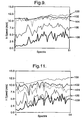
- Figure 9 illustrates the horizontal wind speed measured by a ground based, conically scanned monostatic lidar system over a 20 minute period.
- Lines 100, 102, 104, 106 and 108 show the measured wind speed at heights of 300m, 150m, 100m, 50m and 25m respectively.
- the cloud base was observed to be at a height of around 300m for the duration of the measurements.
- each wind velocity value at each height is determined by acquiring multiple Doppler spectra (of the type shown in figure 3 ) at various points around the scan cone. Line of sight velocity values are then determined by calculating the centroid of each spectrum above a pre-determined threshold. The line of sight velocity values extracted from the spectra are fitted to the expressions described in equations (1) and (2) allowing horizontal and vertical wind speed components to be determined.
- Figure 9 illustrates the horizontal wind speed components calculated in such a manner for a number of heights above the ground without any attempt to correct for returns from the cloud base. It can be seen from figure 9 that the measured wind speeds at 100m (line 104) and 150m (line 102) appear very similar to the measured wind speed at 300m (line 100).
- Figure 10a shows the Doppler spectrum for one measurement point at a measurement height of 150m.
- the Doppler spectrum can be seen to contain a broad peak 110 which corresponds to the return signal from the probe volume (i.e. the region 150m above the ground) and also a sharp peak 112 that arises due to returns from the cloud base (which is at 300m).
- Extracting a line of sight wind velocity value from the Doppler spectrum of figure 10a by calculating the centroid of the spectra above a pre-determined threshold i.e. using the technique described with reference to figure 3
- any wind speed calculated in the manner described above using the entire Doppler spectrum may not be indicative of the true wind velocity in presence of a low cloud base.
- the Doppler spectrum for a measurement point at a height of 300m above the ground is shown after a suitable thresholding step has been applied.
- the spectrum of figure 10b was acquired at substantially the same scan angle as that used to acquire the spectrum of figure 10a .
- the spectrum shown in figure 10b contains a single, sharp, peak 114 that arises due to back-scatter of the laser radiation from the cloud. It can be seen from figures 10a and 10b that the height (i.e. peak return intensity) of the cloud peak 114 of figure 10b is greater than that of the cloud return peak 112 of figure 10a , but that the Doppler shift of both peaks is almost identical.
- the spectrum of figure 10b is subtracted from the spectrum of figure 10a to produce the modified spectrum shown in figure 10c .
- the spectrum of figure 10b is thresholded prior to the subtraction step to prevent additional noise being introduced to the modified spectrum.
- a line of sight wind speed velocity is calculated from the data of figure 10c by determining the centroid of the spectrum above a pre-determined threshold. It can be seen that the cloud peak is removed from the modified data of figure 10c and hence the calculated line of sight wind velocity value reflects the true wind speed at the probe volume (i.e. at 150m above the ground). In other words, the wind speed measurements have been corrected to remove any deleterious effects due to cloud base returns.
- the data correction technique described with reference to figure 10 was repeated for each of the line of sight Doppler spectra from which the wind speed data at heights of 25m, 50m, 100m and 150m of figure 9 were calculated.
- the Doppler spectra acquired from cloud returns i.e. at a height of 300m
- the line of sight velocity values extracted from the spectra were refitted to the expressions described in equations (1) and (2) allowing horizontal and vertical wind speed components to be determined. It should be noted that the outlier removal technique described above was also applied during the line of sight velocity fitting process.
- Figure 11 shows the "corrected" horizontal wind speed components at heights of 25m (line 128), 50m (line 126), 100m (line 124) and 150m (line 122) and the cloud velocity data at 300m (line 100).
- a Doppler wind lidar 90 mounted on the nacelle of a wind turbine 92 is shown.
- the lidar 90 is pointed upwind, through the region swept by the blades of the turbine, to provide advance wind speed measurements.
- the lidar 90 may be scanned, e.g. a conical scan may be performed, to measure different wind velocity components.
- Such advance wind speed measurements may be used for turbine control or to provide gust warnings to protect the turbine from damage due to gusts of wind.
- the reliability of wind speed data acquired from the lidar 90 can, as with upwardly pointing systems, also suffer from erroneous wind speed data points.
- solid objects birds, insects, aircraft etc
- the techniques described above with reference to figure 4 in which "outlier" data points are removed are thus also advantageous when applied to horizontally pointed lidar systems.
- such techniques are particularly advantageous as they allow the removal of any spurious data points that are produced by reflection of light off the turbine blades, reflections from the blades of other turbines in the wind farm or from any wiper system used to keep the lidar output optics free from rain or dirt.
Landscapes
- Engineering & Computer Science (AREA)
- Physics & Mathematics (AREA)
- Computer Networks & Wireless Communication (AREA)
- General Physics & Mathematics (AREA)
- Radar, Positioning & Navigation (AREA)
- Remote Sensing (AREA)
- Electromagnetism (AREA)
- Optical Radar Systems And Details Thereof (AREA)
Claims (24)
- Radarvorrichtung (2) für kohärentes Laserlicht zur Messung von atmosphärischen Windgeschwindigkeiten, die umfaßt:einen Sender zur Fokussierung eines Lichtstrahls (4) auf eines von mehreren entfernten Untersuchungsvolumina (6), wobei der Sender einen variablen Fokusmechanismus aufweist und so ausgeführt ist, dass er sequentiell Licht auf die mehreren entfernten Untersuchungsvolumina fokussiert, die mindestens ein entferntes Meßuntersuchungsvolumen und mindestens ein entferntes Referenzuntersuchungsvolumen darstellen,einen Empfänger zur Erfassung des zurückgestreuten Lichts undeine Analyseeinrichtung zur Berechnung der Windgeschwindigkeit an dem entfernten Meßuntersuchungsvolumen oder jedem entfernten Meßuntersuchungsvolumen aus der Doppler-Frequenzverschiebung des erfaßten zurückgestreuten Lichts,dadurch gekennzeichnet,
dass die Analyseeinrichtung so ausgeführt ist, dass sie Doppler-Spektren erzeugt, welche die Intensität des erfaßten zurückgestreuten Lichts als Funktion der Doppler-Frequenzverschiebung für jede Messung an jedem Volumen des Meßuntersuchungsvolumens und des Referenzuntersuchungsvolumens enthalten und dass mindestens ein Doppler-Spektrum verwendet wird, das für ein entferntes Referenzuntersuchungsvolumen erzeugt wurde, um dieses oder jedes Doppler-Spektrum zu korrigieren, das für ein Meßuntersuchungsvolumen für jede Doppler-Frequenzkomponente des erfaßten zurückgestreuten Lichts erzeugt wurde, welches als Rückstreuung von Wolken auftritt, die sich in einer Entfernung befinden, die größer als die Entfernung des entfernten Untersuchungsvolumens ist. - Vorrichtung nach Anspruch 1, bei der der Schritt der Korrektur des oder jedes für ein Meßuntersuchungsvolumen erzeugten Doppler-Spektrums die Subtraktion mindestens eines Referenz-Doppler-Spektrums von jedem der Meß-Doppler-Spektren umfaßt.
- Vorrichtung nach einem der vorhergehenden Ansprüche, die ferner eine Einrichtung (82) zur Erzeugung eines Profils der atmosphärischen Rückstreuung zur Messung des Querschnitts der Rückstreuung aus der Atmosphäre als eine Funktion der Entfernung umfaßt.
- Vorrichtung nach Anspruch 3, bei der die Analyseeinrichtung derart ausgeführt ist, dass sie das von der Einrichtung (82) zur Erzeugung eines Profils der atmosphärischen Rückstreuung gemessene Rückstreuprofil wählt und dieses Profil im Schritt der Korrektur des oder jedes Doppler-Spektrums verwendet, das für ein Meßuntersuchungsvolumen erzeugt wurde, um zu gewährleisten, dass die berechnete Windgeschwindigkeit in Bezug auf jede Doppler-Frequenzkomponente des erfaßten zurückgestreuten Lichts korrigiert wird, das durch die Rückstreuung von Wolken auftritt, die sich in einer Entfernung befinden, die größer als die Entfernung des entfernten Untersuchungsvolumens ist.
- Vorrichtung nach einem der vorhergehenden Ansprüche, bei der eine Abtasteinrichtung zum Abtasten (22) des vom Sender im entfernten Untersuchungsvolumen durchgelassenen Lichtstrahls vorgesehen ist.
- Vorrichtung nach Anspruch 5, bei der die Analyseeinrichtung so ausgeführt ist, dass sie einen Sichtlinien-Windgeschwindigkeitswert für mehrere bekannte Abtastpositionen innerhalb des entfernten Untersuchungsvolumens bestimmt und mindestens eine Windgeschwindigkeitskomponente am entfernten Untersuchungsvolumen berechnet, indem die mehreren Sichtlinien-Geschwindigkeitswerte an eine vorgegebene Funktion angepaßt werden.
- Vorrichtung nach Anspruch 6, bei der die Analyseeinrichtung derart ausgeführt ist, dass sie gewährleistet, dass jeder berechnete Sichtlinien-Geschwindigkeitswert in Bezug auf jede Doppler-Frequenzkomponente des erfaßten zurückgestreuten Lichts korrigiert wird, die durch Rückstreuung von Wolken auftritt, die sich in einer Entfernung befinden, die größer als die Entfernung des entfernten Untersuchungsvolumens ist.
- Vorrichtung nach einem der Ansprüche 6 bis 7, bei der die Analyseeinrichtung derart ausgeführt ist, dass ein oder mehrere Sichtlinien-Geschwindigkeitswerte, die beim Abtasten erhalten wurden, bei der Berechnung der mindestens einen Windgeschwindigkeitskomponente nicht berücksichtigt werden.
- Vorrichtung nach einem der vorhergehenden Ansprüche, bei der im Betrieb der Fokus des Empfangsstrahls so angeordnet ist, dass er mit dem Fokus des Sendestrahls zusammenfällt.
- Vorrichtung nach einem der vorhergehenden Ansprüche, bei der die Vorrichtung monostatisch ist.
- Vorrichtung nach einem der vorhergehenden Ansprüche, bei der das zurückgestreute, vom Empfänger aufgefangene Licht mit einem lokalen Oscillatorsignal gemischt wird, das vor der Erfassung aus der Lichtquelle des Senders gewonnen wurde.
- Vorrichtung nach einem der vorhergehenden Ansprüche, die mindestens ein Stück eines Lichtwellenleiters enthält.
- Vorrichtung nach einem der vorhergehenden Ansprüche, die für einen nach oben gerichteten Bodenbetrieb ausgeführt ist.
- Verfahren zur Berechnung der atmosphärischen Windgeschwindigkeit, das die folgenden Schritte umfaßt:(i) Erfassung der Doppler-Frequenzdaten, die von einer Radarvorrichtung (2) für kohärentes Laserlicht von mehreren entfernten Untersuchungsvolumina (6) erhalten wurden, und Ausbildung eines ersten Satzes Doppler-Spektren, die von einem oder mehreren entfernten Meßuntersuchungsvolumina in einer Entfernung erhalten wurden, die geringer als ein erster Entfernungsgrenzwert ist, und eines zweiten Satzes Doppler-Spektren, die von einem oder mehreren entfernten Meßuntersuchungsvolumina in einer Entfernung erhalten wurden, die größer als der erste Entfernungsgrenzwert ist, und(ii) Berechnung der Windgeschwindigkeit an dem entfernten Untersuchungsvolumen der Radarvorrichtung (2) für kohärentes Laserlicht aus den Doppler-Frequenzdaten,dadurch gekennzeichnet,
dass der Schritt (ii) die Verwendung des zweiten Satzes Doppler-Spektren umfaßt, um zu gewährleisten, dass die Windgeschwindigkeit, die von jedem Spektrum des ersten Satzes Doppler-Spektren berechnet wurde, hinsichtlich jeder Doppler-Frequenzkomponente korrigiert wird, die aus der Rückstreuung von Wolken auftritt, die sich in einer Entfernung befinden, die größer als die Entfernung des entfernten Untersuchungsvolumens ist. - Verfahren nach Anspruch 14, bei dem die Berechnung der Windgeschwindigkeit den Schritt der Subtraktion eines Doppler-Spektrums des zweiten Satzes Doppler-Spektren von jedem Dopplerspektrum des ersten Satzes Doppler-Spektren umfaßt.
- Verfahren nach einem der Ansprüche 14 oder 15, welches den zusätzlichen Schritt der Verwendung eines von einer Einrichtung (82) zur Erzeugung eines Profils der atmosphärischen Rückstreuung gemessenen Rückstreuprofils umfaßt, die in der Nähe der Radarvorrichtung (2) für kohärentes Laserlicht angeordnet ist, sowie den Schritt der Verwendung des Rückstreuprofils im Schritt der Korrektur der Windgeschwindigkeit umfaßt, die aus jedem Doppler-Spektrum des ersten Satzes Doppler-Spektren berechnet wird.
- Verfahren nach einem der Ansprüche 14 bis 16, bei dem die Doppler-Frequenzdaten mehre Doppler-Spektren umfassen, die von jedem entfernten Untersuchungsvolumen erhalten werden, wobei jedes der mehreren Doppler-Spektren von einer bekannten Abtastposition innerhalb des entfernten Untersuchungsvolumens erhalten wird.
- Verfahren nach Anspruch 17, bei dem von jedem Doppler-Spektrum jeder Abtastposition im entfernten Untersuchungsvolumen ein Sichtlinien-Geschwindigkeitswert berechnet wird, wobei der Schritt der Berechnung der Windgeschwindigkeit an einem entfernten Untersuchungsvolumen den Schritt der Anpassung mindestens einiger der Sichtlinien-Geschwindigkeitswerte an eine vorgegebene Funktion umfaßt.
- Verfahren nach Anspruch 18, bei dem mindestens einige Sichtlinien-Geschwindigkeitswerte, die zur Verwendung im Schritt der Berechnung der mindestens einen Windgeschwindigkeitskomponente an einem entfernten Untersuchungsvolumen ausgewählt wurden, Sichtlinien-Geschwindigkeitswerte enthalten, die eine Abweichung von einem ursprünglich angepaßten Wert aufweisen, die kleiner als eine vorgegebene Größe ist.
- Verfahren nach Anspruch 18, bei der die mindestens einigen Sichtlinien-Geschwindigkeitswerte, die zur Verwendung im Schritt der Berechnung der mindestens einen Windgeschwindigkeitskomponente an einem entfernten Untersuchungsvolumen ausgewählt wurden, die Linie N der Sichtlinien-Geschwindigkeitswerte ausschließen, welche die höchste Abweichung von einem ursprünglichen angepaßten Wert aufweist, wobei N eine vorgegebene ganze Zahl ist, die größer als oder gleich Eins und kleiner als oder gleich der Zahl der Sichtlinien-Geschwindigkeitswerte ist.
- Verfahren nach einem der Ansprüche 14 bis 20, bei dem Schritt (i) den Schritt der Verwendung einer Radarvorrichtung (2) für kohärentes Laserlicht für die Gewinnung von Doppler-Frequenzdaten von mindestens einem entfernten Untersuchungsvolumen umfaßt.
- Computerprogramm zur Ausführung des Verfahrens der Ansprüche 14 bis 20.
- Computerprogramm-Träger, der ein Computerprogramm in maschinenlesbarer Form enthält, das zur Ausführung des Verfahrens der Ansprüche 14 bis 20 geeignet ist.
- In geeigneter Weise programmierter Computer zur Ausführung des Verfahrens der Ansprüche 14 bis 20.
Applications Claiming Priority (2)
| Application Number | Priority Date | Filing Date | Title |
|---|---|---|---|
| GBGB0411097.9A GB0411097D0 (en) | 2004-05-19 | 2004-05-19 | Laser radar device and method |
| PCT/GB2005/001943 WO2005114253A1 (en) | 2004-05-19 | 2005-05-18 | Laser radar device and method |
Publications (2)
| Publication Number | Publication Date |
|---|---|
| EP1749219A1 EP1749219A1 (de) | 2007-02-07 |
| EP1749219B1 true EP1749219B1 (de) | 2008-10-29 |
Family
ID=32607540
Family Applications (1)
| Application Number | Title | Priority Date | Filing Date |
|---|---|---|---|
| EP05744679A Expired - Lifetime EP1749219B1 (de) | 2004-05-19 | 2005-05-18 | Laserradarvorrichtung und verfahren |
Country Status (11)
| Country | Link |
|---|---|
| US (1) | US7391506B2 (de) |
| EP (1) | EP1749219B1 (de) |
| JP (1) | JP2007538245A (de) |
| AT (1) | ATE412919T1 (de) |
| AU (1) | AU2005246082B2 (de) |
| CA (1) | CA2562924C (de) |
| DE (1) | DE602005010692D1 (de) |
| DK (1) | DK1749219T3 (de) |
| ES (1) | ES2313345T3 (de) |
| GB (1) | GB0411097D0 (de) |
| WO (1) | WO2005114253A1 (de) |
Cited By (1)
| Publication number | Priority date | Publication date | Assignee | Title |
|---|---|---|---|---|
| FR2948459A1 (fr) * | 2009-07-24 | 2011-01-28 | Thales Sa | Procede et systeme d'anemometrie mono-particule par lidar |
Families Citing this family (74)
| Publication number | Priority date | Publication date | Assignee | Title |
|---|---|---|---|---|
| GB0515605D0 (en) | 2005-07-29 | 2005-09-07 | Qinetiq Ltd | Laser measurement device and method |
| US7742152B2 (en) * | 2006-06-23 | 2010-06-22 | University Of Kansas | Coherent detection scheme for FM chirped laser radar |
| US8085157B2 (en) * | 2007-10-24 | 2011-12-27 | Honeywell International Inc. | Smoke detectors |
| WO2010031161A1 (en) * | 2008-09-16 | 2010-03-25 | Her Majesty The Queen In Right Of Canada As Represented By The Minister Of Defence | Standoff determination of the size and concentration of low concentration aerosols |
| FR2938075B1 (fr) * | 2008-11-05 | 2015-09-25 | Airbus France | Dispositif et procede de detection et de mesure de vent pour aeronef |
| EP2353031A1 (de) * | 2008-11-05 | 2011-08-10 | Airbus Operations | Einrichtung und verfahren zum detektieren und messen von wind für ein flugzeug |
| EP2213875A1 (de) * | 2009-01-30 | 2010-08-04 | Siemens Aktiengesellschaft | Verfahren und Anordnung zur Vorhersage der Leistung von mindestens einer Windturbine |
| US8797550B2 (en) | 2009-04-21 | 2014-08-05 | Michigan Aerospace Corporation | Atmospheric measurement system |
| WO2011016892A2 (en) * | 2009-05-15 | 2011-02-10 | Michigan Aerospace Corporation | Range imaging lidar |
| JP5207252B2 (ja) * | 2009-05-20 | 2013-06-12 | 日本電信電話株式会社 | 光周波数領域反射測定方法及び光周波数領域反射測定装置 |
| WO2014084973A1 (en) * | 2012-11-30 | 2014-06-05 | HAYES, Paul, Byron | Atmospheric measurement system |
| BR112012006806A2 (pt) | 2009-09-28 | 2020-08-18 | Pentalum Technologies Ltd. | sistema e método para monitorar características de vento em um volume, anemômetro a laser, sistema e método para controlar a operação de múltiplas turbinas eólicas |
| US8025476B2 (en) * | 2009-09-30 | 2011-09-27 | General Electric Company | System and methods for controlling a wind turbine |
| FR2952722B1 (fr) | 2009-11-18 | 2011-12-09 | Onera (Off Nat Aerospatiale) | Mesure de caracteristiques velocimetriques ou vibrometriques utilisant un dispositif de type lidar a detection heterodyne |
| WO2011072160A2 (en) | 2009-12-09 | 2011-06-16 | The Research Foundation Of State University Of New York | Inter-node communication method and system |
| US20110149268A1 (en) * | 2009-12-17 | 2011-06-23 | Marchant Alan B | Dynamic 3d wind mapping system and method |
| JP5435122B2 (ja) * | 2010-02-24 | 2014-03-05 | 富士通株式会社 | 環境測定システム及び環境測定方法 |
| US8325327B2 (en) * | 2010-06-15 | 2012-12-04 | Bluescout Technologies, Inc. | Using remotely detected wind velocities to enhance understanding of an impending or occurring event |
| WO2012010839A1 (en) | 2010-07-22 | 2012-01-26 | Renishaw Plc | Laser scanning apparatus and method of use |
| US8202049B2 (en) * | 2010-08-31 | 2012-06-19 | Catch the Wind, Inc. | Independent blade pitch control |
| GB2484493C (en) * | 2010-10-12 | 2019-02-13 | Tmd Tech Limited | Radar system |
| CN203685475U (zh) | 2011-01-31 | 2014-07-02 | 通用电气公司 | 风力涡轮机控制系统及风力涡轮机系统 |
| EP2702393B1 (de) * | 2011-04-28 | 2017-04-12 | Vestas Wind Systems A/S | Verfahren und vorrichtung für den schutz von windturbinen vor extremen ereignissen |
| FI125286B (fi) * | 2011-07-01 | 2015-08-14 | Teknologian Tutkimuskeskus Vtt Oy | Järjestely ja menetelmä jäätymisen havainnoimiseksi |
| JP5881099B2 (ja) * | 2011-10-06 | 2016-03-09 | 国立研究開発法人宇宙航空研究開発機構 | 光学式遠隔気流計測装置の有色ノイズ低減方法とその装置 |
| US9234506B2 (en) * | 2011-10-14 | 2016-01-12 | Vestas Wind Systems A/S | Estimation of wind properties using a light detection and ranging device |
| US9217415B2 (en) * | 2011-10-14 | 2015-12-22 | Vestas Wind Systems A/S | Estimation of wind properties using a light detection and ranging device |
| RU2494422C2 (ru) * | 2011-12-29 | 2013-09-27 | Федеральное государственное бюджетное образовательное учреждение высшего профессионального образования "Московский государственный технический университет имени Н.Э. Баумана" (МГТУ им. Н.Э. Баумана) | Лазерный дистанционный способ оценки мгновенной скорости и направления ветра |
| EP2866050B1 (de) * | 2012-06-25 | 2018-08-01 | Mitsubishi Electric Corporation | Kohärente lidar-vorrichtung zur windmessung |
| EP2896972B1 (de) * | 2012-09-14 | 2019-10-30 | Mitsubishi Electric Corporation | Laserradarvorrichtung und verfahren für den nachweis der geschwindigkeit eines gemessenen objekts |
| EP2730947A1 (de) | 2012-11-12 | 2014-05-14 | Technische Universität Hamburg-Harburg | Lidar-Messsystem und Lidar-Messverfahren |
| US9851470B2 (en) * | 2013-03-12 | 2017-12-26 | LogLinear Group, LLC | Single beam FMCW radar wind speed and direction determination |
| WO2014162720A1 (ja) * | 2013-04-01 | 2014-10-09 | 三菱電機株式会社 | 光学装置、ライダ装置及び撮像装置 |
| US20140312620A1 (en) * | 2013-04-17 | 2014-10-23 | General Electric Company | Method and apparatus for improving grid stability in a wind farm |
| US9606234B2 (en) | 2013-10-18 | 2017-03-28 | Tramontane Technologies, Inc. | Amplified optical circuit |
| CN103969694A (zh) * | 2014-05-19 | 2014-08-06 | 西安电子科技大学 | 基于激光后向散射多普勒频移的水中目标尾迹探测方法 |
| CN103983975B (zh) * | 2014-06-05 | 2017-01-11 | 中国气象局气象探测中心 | 基于两种雷达的大气运动垂直速度检测方法及系统 |
| US9766262B2 (en) * | 2014-11-10 | 2017-09-19 | Raytheon Company | System and method for measuring doppler effect utilizing elastic and inelastic light scattering |
| DE102015004272B4 (de) | 2015-04-07 | 2019-05-29 | Metek Meteorologische Messtechnik Gmbh | Störlicht-tolerantes Lidar-Messsystem und Störlicht-tolerantes Lidar-Messverfahren |
| JP6257845B2 (ja) * | 2015-05-12 | 2018-01-10 | 三菱電機株式会社 | レーザレーダ装置及び風速観測方法 |
| CN105137451B (zh) * | 2015-08-26 | 2018-07-06 | 中国科学技术大学 | 一种基于1μm~2μm气体分子吸收谱线的全光纤测风激光雷达 |
| US10451407B2 (en) * | 2015-11-23 | 2019-10-22 | The Boeing Company | System and method of analyzing a curved surface |
| US10338202B2 (en) * | 2016-01-28 | 2019-07-02 | General Electric Company | System and method for improving LIDAR sensor signal availability on a wind turbine |
| JP6387986B2 (ja) * | 2016-02-26 | 2018-09-12 | 三菱電機株式会社 | 光学望遠鏡の観測計画作成支援装置およびシステム |
| US10451518B2 (en) * | 2016-05-10 | 2019-10-22 | Rd2, Llc | All fiber temperature and air density sensor |
| US10539116B2 (en) | 2016-07-13 | 2020-01-21 | General Electric Company | Systems and methods to correct induction for LIDAR-assisted wind turbine control |
| US9926912B2 (en) * | 2016-08-30 | 2018-03-27 | General Electric Company | System and method for estimating wind coherence and controlling wind turbine based on same |
| FR3059433B1 (fr) * | 2016-11-28 | 2019-05-17 | Thales | Procede d'identification d'un obstacle solide dans un faisceau laser d'un systeme lidar et systeme associe |
| CN106772440B (zh) * | 2017-01-12 | 2023-09-19 | 杭州赛尤新能源科技有限公司 | 采用变频激光测风雷达的测风系统及变频控制方法 |
| JP6505343B2 (ja) * | 2017-01-24 | 2019-04-24 | 三菱電機株式会社 | レーザレーダ装置 |
| DE102017106226A1 (de) | 2017-03-22 | 2018-09-27 | Metek Meteorologische Messtechnik Gmbh | LIDAR-Messeinrichtung |
| US20190003455A1 (en) * | 2017-06-29 | 2019-01-03 | Siemens Aktiengesellschaft | Method and arrangement for detecting a shadow condition of a wind turbine |
| PL238221B1 (pl) * | 2017-07-19 | 2021-07-26 | Przybycin Michal | Układ rejestrujący kolizje zwierząt latających z elektrowniami wiatrowymi i wskazujący miejsce ich upadku na podłoże |
| CN108490451B (zh) * | 2018-03-29 | 2022-03-25 | 中国民航大学 | 一种利用大气消光系数反演斜程能见度的方法 |
| CN111989593B (zh) * | 2018-04-26 | 2024-05-14 | 三菱电机株式会社 | 激光雷达装置、风力发电装置以及风测量方法 |
| WO2019216086A1 (ja) * | 2018-05-09 | 2019-11-14 | 古野電気株式会社 | 気象レーダ装置、気象観測方法、および、気象観測プログラム |
| US10551485B1 (en) * | 2018-08-06 | 2020-02-04 | Luminar Technologies, Inc. | Fitting points to a surface |
| EP3715908B1 (de) * | 2019-03-27 | 2024-11-20 | MicroVision, Inc. | Verfahren und vorrichtung zur optischen distanzmessung |
| CN110133614B (zh) * | 2019-05-14 | 2022-03-22 | 哈尔滨工业大学 | 基于改进核心的BRDF模型的Gm-APD激光雷达回波能量计算方法 |
| EP3982158A4 (de) * | 2019-06-06 | 2022-08-17 | Mitsubishi Electric Corporation | Kohärente lidar-vorrichtung |
| CN110456382B (zh) * | 2019-07-12 | 2023-02-21 | 中国海洋大学 | 基于单多普勒激光雷达的非均匀风场风矢量的测量方法 |
| FR3110002B1 (fr) * | 2020-05-06 | 2022-04-22 | Office National D’ Etudes Et De Rech Aerospatiales | Detection et telemetrie par impulsions de rayonnement electromagnetique |
| CN111929702B (zh) * | 2020-09-23 | 2020-12-25 | 中国人民解放军国防科技大学 | 空中目标大气扰动变分辨率探测方法、存储介质和系统 |
| FR3115115B1 (fr) * | 2020-10-14 | 2022-10-14 | Ifp Energies Now | Procédé de détermination d’un facteur d’induction entre un plan de mesure et le plan du rotor d’une éolienne |
| CN112526548B (zh) * | 2020-11-18 | 2024-02-23 | 南京泰爱信科技有限公司 | 一种基于测风激光雷达的降雨识别方法及装置 |
| CN114690157A (zh) * | 2020-12-30 | 2022-07-01 | 北京万集科技股份有限公司 | 激光雷达反射率的自动标定方法、目标检测方法以及装置 |
| CN113311436B (zh) * | 2021-04-30 | 2022-07-12 | 中国人民解放军国防科技大学 | 一种移动平台上激光测风雷达运动姿态测风订正方法 |
| CN113835104A (zh) * | 2021-11-04 | 2021-12-24 | 华能新能源股份有限公司 | 一种复杂地形三维扫描雷达测风系统、方法及设备 |
| GB2613870B (en) * | 2021-12-17 | 2024-05-15 | Zephir Ltd | Lidar measurement |
| KR102871397B1 (ko) * | 2022-10-24 | 2025-10-22 | 한국전자통신연구원 | 레이더 기반의 에고-모션 추정에서 동적 객체 필터링 방법 및 장치 |
| CN116430365B (zh) * | 2023-03-10 | 2023-10-24 | 中国科学院国家空间科学中心 | 基于回波信号实时监测激光雷达探测波长的系统及方法 |
| CN115980788B (zh) * | 2023-03-17 | 2023-06-06 | 安徽科创中光科技股份有限公司 | 一种相干测风激光雷达的风场处理方法 |
| US12555484B2 (en) * | 2023-08-29 | 2026-02-17 | Honeywell International Inc. | Systems and methods for diminishing vehicle contrails |
| GB202404583D0 (en) * | 2024-03-28 | 2024-05-15 | Zephir Ltd | Lidar measurement |
Family Cites Families (15)
| Publication number | Priority date | Publication date | Assignee | Title |
|---|---|---|---|---|
| DE3520214C1 (de) * | 1985-06-05 | 1986-07-10 | Deutsche Forschungs- und Versuchsanstalt für Luft- und Raumfahrt e.V., 5300 Bonn | Messeinrichtung zur Bestimmung der Windrichtung und Windgeschwindigkeit in der Atmosphaere |
| FR2663752B1 (fr) * | 1990-06-25 | 1993-01-22 | Seso | Dispositif de mesure de parametres meteorologiques. |
| US5724125A (en) * | 1994-06-22 | 1998-03-03 | Ames; Lawrence L. | Determination of wind velocity using a non-vertical LIDAR scan |
| JP2000000107A (ja) | 1998-06-16 | 2000-01-07 | Kao Corp | 締結具 |
| JP3322214B2 (ja) * | 1998-06-17 | 2002-09-09 | 三菱電機株式会社 | 気流検出方法およびレーザレーダ装置 |
| GB9926516D0 (en) * | 1999-11-10 | 2000-01-12 | Secr Defence | Doppler sensor apparatus |
| DE10012395B4 (de) * | 2000-03-15 | 2010-04-29 | Abb Research Ltd. | Durchflussmesser |
| EP1307714A4 (de) * | 2000-07-12 | 2007-04-04 | Macquarie Res Ltd | Optische heterodyndetektion bei der otpischen cavity-ringdown-spektroskopie |
| JP4740449B2 (ja) * | 2000-12-27 | 2011-08-03 | 富士通テン株式会社 | 車載用レーダの上下軸ずれ検出装置 |
| ES2272433T3 (es) * | 2001-10-05 | 2007-05-01 | Datalogic S.P.A. | Aparato de lectura optica. |
| SE522181C2 (sv) * | 2001-10-30 | 2004-01-20 | Totalfoersvarets Forskningsins | Laserradarsystem och metod för vindmätning |
| WO2003100458A1 (fr) | 2002-05-29 | 2003-12-04 | Mitsubishi Denki Kabushiki Kaisha | Dispositif radar doppler a laser |
| US7142562B2 (en) * | 2002-07-01 | 2006-11-28 | Nortel Networks Limited | Adaptive data rate control for mobile data transfer for high throughput and guaranteed error rate |
| JP3794361B2 (ja) * | 2002-08-28 | 2006-07-05 | 三菱電機株式会社 | レーダ信号処理装置及びレーダ信号処理方法 |
| GB0223512D0 (en) | 2002-10-10 | 2002-11-13 | Qinetiq Ltd | Bistatic laser radar apparatus |
-
2004
- 2004-05-19 GB GBGB0411097.9A patent/GB0411097D0/en not_active Ceased
-
2005
- 2005-05-18 US US11/578,720 patent/US7391506B2/en not_active Expired - Lifetime
- 2005-05-18 AU AU2005246082A patent/AU2005246082B2/en not_active Expired
- 2005-05-18 ES ES05744679T patent/ES2313345T3/es not_active Expired - Lifetime
- 2005-05-18 JP JP2007517417A patent/JP2007538245A/ja active Pending
- 2005-05-18 AT AT05744679T patent/ATE412919T1/de not_active IP Right Cessation
- 2005-05-18 WO PCT/GB2005/001943 patent/WO2005114253A1/en not_active Ceased
- 2005-05-18 CA CA2562924A patent/CA2562924C/en not_active Expired - Lifetime
- 2005-05-18 DK DK05744679T patent/DK1749219T3/da active
- 2005-05-18 DE DE602005010692T patent/DE602005010692D1/de not_active Expired - Lifetime
- 2005-05-18 EP EP05744679A patent/EP1749219B1/de not_active Expired - Lifetime
Cited By (3)
| Publication number | Priority date | Publication date | Assignee | Title |
|---|---|---|---|---|
| FR2948459A1 (fr) * | 2009-07-24 | 2011-01-28 | Thales Sa | Procede et systeme d'anemometrie mono-particule par lidar |
| EP2282216A3 (de) * | 2009-07-24 | 2011-03-16 | Thales | Verfahren und System zur Einzelteilchenanemometrie durch LIDAR |
| US8325328B2 (en) | 2009-07-24 | 2012-12-04 | Thales | Single-particle LIDAR anemometry method and system |
Also Published As
| Publication number | Publication date |
|---|---|
| CA2562924A1 (en) | 2005-12-01 |
| AU2005246082B2 (en) | 2010-04-01 |
| EP1749219A1 (de) | 2007-02-07 |
| ATE412919T1 (de) | 2008-11-15 |
| GB0411097D0 (en) | 2004-06-23 |
| WO2005114253A1 (en) | 2005-12-01 |
| DE602005010692D1 (de) | 2008-12-11 |
| US7391506B2 (en) | 2008-06-24 |
| CA2562924C (en) | 2014-05-06 |
| JP2007538245A (ja) | 2007-12-27 |
| US20070171396A1 (en) | 2007-07-26 |
| DK1749219T3 (da) | 2009-03-09 |
| ES2313345T3 (es) | 2009-03-01 |
| AU2005246082A1 (en) | 2005-12-01 |
Similar Documents
| Publication | Publication Date | Title |
|---|---|---|
| EP1749219B1 (de) | Laserradarvorrichtung und verfahren | |
| EP1910869B1 (de) | Lasermesseinrichtung und -verfahren | |
| Smith et al. | Wind lidar evaluation at the Danish wind test site in Høvsøre | |
| Thiel et al. | Performance capabilities of laser scanners–an overview and measurement principle analysis | |
| JP2007538245A5 (de) | ||
| Sathe et al. | Estimating turbulence statistics and parameters from ground-and nacelle-based lidar measurements: IEA Wind expert report | |
| Harris et al. | Advance measurement of gusts by laser anemometry | |
| Courtney et al. | Commercial lidar profilers for wind energy: A comparative guide | |
| Rocadenbosch et al. | Ceilometer-based rain-rate estimation: A case-study comparison with S-band radar and disdrometer retrievals in the context of VORTEX-SE | |
| Antoniou et al. | Remote sensing the wind using Lidars and Sodars | |
| Angelou et al. | UniTTe WP3/MC1: Measuring the inflow towards a Nordtank 500kW turbine using three short-range WindScanners and one SpinnerLidar | |
| Zong et al. | Relationship between cloud characteristics and radar reflectivity based on aircraft and cloud radar co-observations | |
| Fan et al. | Wind speed estimation using FRFT-based method for mmWave wind profiler radar in low SNR conditions | |
| Lindelöw-Marsden | UpWind D1. Uncertainties in wind assessment with LIDAR | |
| Jin et al. | Suppression of precipitation bias on wind velocity from continuous-wave Doppler lidars | |
| Jin et al. | Suppression of precipitation bias in wind velocities from continuous-wave Doppler lidars | |
| Watkins et al. | Observations of clear air turbulence and winds with the Millstone Hill radar | |
| Hajipour et al. | Identification of multiple co-located hydrometeor types in Doppler spectra from scanning polarimetric cloud radar observations | |
| Sjöholm et al. | EROSION | |
| Thiel et al. | A new algorithm for processing fullwave laser scanner data | |
| CN118276035B (zh) | 局部地区的土壤-植被-大气垂向结构同步监测方法 | |
| Clive | Compensation of vector and volume averaging bias in lidar wind speed measurements | |
| Bozier et al. | Evaluating the precision of a transverse excitation atmospheric based CO2 Doppler lidar system with in situ sensors | |
| Divjak et al. | Radar data quality-ensuring procedures at European weather radar stations | |
| Hill et al. | Remote sensing (upwind wp6) qinetiq lidar measurement report |
Legal Events
| Date | Code | Title | Description |
|---|---|---|---|
| PUAI | Public reference made under article 153(3) epc to a published international application that has entered the european phase |
Free format text: ORIGINAL CODE: 0009012 |
|
| 17P | Request for examination filed |
Effective date: 20061021 |
|
| AK | Designated contracting states |
Kind code of ref document: A1 Designated state(s): AT BE BG CH CY CZ DE DK EE ES FI FR GB GR HU IE IS IT LI LT LU MC NL PL PT RO SE SI SK TR |
|
| 17Q | First examination report despatched |
Effective date: 20070326 |
|
| DAX | Request for extension of the european patent (deleted) | ||
| GRAP | Despatch of communication of intention to grant a patent |
Free format text: ORIGINAL CODE: EPIDOSNIGR1 |
|
| GRAS | Grant fee paid |
Free format text: ORIGINAL CODE: EPIDOSNIGR3 |
|
| GRAA | (expected) grant |
Free format text: ORIGINAL CODE: 0009210 |
|
| AK | Designated contracting states |
Kind code of ref document: B1 Designated state(s): AT BE BG CH CY CZ DE DK EE ES FI FR GB GR HU IE IS IT LI LT LU MC NL PL PT RO SE SI SK TR |
|
| REG | Reference to a national code |
Ref country code: GB Ref legal event code: FG4D |
|
| REG | Reference to a national code |
Ref country code: CH Ref legal event code: EP |
|
| REG | Reference to a national code |
Ref country code: IE Ref legal event code: FG4D |
|
| REF | Corresponds to: |
Ref document number: 602005010692 Country of ref document: DE Date of ref document: 20081211 Kind code of ref document: P |
|
| REG | Reference to a national code |
Ref country code: ES Ref legal event code: FG2A Ref document number: 2313345 Country of ref document: ES Kind code of ref document: T3 |
|
| REG | Reference to a national code |
Ref country code: DK Ref legal event code: T3 |
|
| NLV1 | Nl: lapsed or annulled due to failure to fulfill the requirements of art. 29p and 29m of the patents act | ||
| LTIE | Lt: invalidation of european patent or patent extension |
Effective date: 20081029 |
|
| PG25 | Lapsed in a contracting state [announced via postgrant information from national office to epo] |
Ref country code: AT Free format text: LAPSE BECAUSE OF FAILURE TO SUBMIT A TRANSLATION OF THE DESCRIPTION OR TO PAY THE FEE WITHIN THE PRESCRIBED TIME-LIMIT Effective date: 20081029 Ref country code: BG Free format text: LAPSE BECAUSE OF FAILURE TO SUBMIT A TRANSLATION OF THE DESCRIPTION OR TO PAY THE FEE WITHIN THE PRESCRIBED TIME-LIMIT Effective date: 20090129 Ref country code: LT Free format text: LAPSE BECAUSE OF FAILURE TO SUBMIT A TRANSLATION OF THE DESCRIPTION OR TO PAY THE FEE WITHIN THE PRESCRIBED TIME-LIMIT Effective date: 20081029 |
|
| PG25 | Lapsed in a contracting state [announced via postgrant information from national office to epo] |
Ref country code: PL Free format text: LAPSE BECAUSE OF FAILURE TO SUBMIT A TRANSLATION OF THE DESCRIPTION OR TO PAY THE FEE WITHIN THE PRESCRIBED TIME-LIMIT Effective date: 20081029 Ref country code: IS Free format text: LAPSE BECAUSE OF FAILURE TO SUBMIT A TRANSLATION OF THE DESCRIPTION OR TO PAY THE FEE WITHIN THE PRESCRIBED TIME-LIMIT Effective date: 20090228 Ref country code: FI Free format text: LAPSE BECAUSE OF FAILURE TO SUBMIT A TRANSLATION OF THE DESCRIPTION OR TO PAY THE FEE WITHIN THE PRESCRIBED TIME-LIMIT Effective date: 20081029 Ref country code: NL Free format text: LAPSE BECAUSE OF FAILURE TO SUBMIT A TRANSLATION OF THE DESCRIPTION OR TO PAY THE FEE WITHIN THE PRESCRIBED TIME-LIMIT Effective date: 20081029 Ref country code: PT Free format text: LAPSE BECAUSE OF FAILURE TO SUBMIT A TRANSLATION OF THE DESCRIPTION OR TO PAY THE FEE WITHIN THE PRESCRIBED TIME-LIMIT Effective date: 20090330 Ref country code: SI Free format text: LAPSE BECAUSE OF FAILURE TO SUBMIT A TRANSLATION OF THE DESCRIPTION OR TO PAY THE FEE WITHIN THE PRESCRIBED TIME-LIMIT Effective date: 20081029 |
|
| PG25 | Lapsed in a contracting state [announced via postgrant information from national office to epo] |
Ref country code: EE Free format text: LAPSE BECAUSE OF FAILURE TO SUBMIT A TRANSLATION OF THE DESCRIPTION OR TO PAY THE FEE WITHIN THE PRESCRIBED TIME-LIMIT Effective date: 20081029 Ref country code: BE Free format text: LAPSE BECAUSE OF FAILURE TO SUBMIT A TRANSLATION OF THE DESCRIPTION OR TO PAY THE FEE WITHIN THE PRESCRIBED TIME-LIMIT Effective date: 20081029 Ref country code: RO Free format text: LAPSE BECAUSE OF FAILURE TO SUBMIT A TRANSLATION OF THE DESCRIPTION OR TO PAY THE FEE WITHIN THE PRESCRIBED TIME-LIMIT Effective date: 20081029 |
|
| PG25 | Lapsed in a contracting state [announced via postgrant information from national office to epo] |
Ref country code: CZ Free format text: LAPSE BECAUSE OF FAILURE TO SUBMIT A TRANSLATION OF THE DESCRIPTION OR TO PAY THE FEE WITHIN THE PRESCRIBED TIME-LIMIT Effective date: 20081029 Ref country code: SE Free format text: LAPSE BECAUSE OF FAILURE TO SUBMIT A TRANSLATION OF THE DESCRIPTION OR TO PAY THE FEE WITHIN THE PRESCRIBED TIME-LIMIT Effective date: 20090129 Ref country code: IT Free format text: LAPSE BECAUSE OF FAILURE TO SUBMIT A TRANSLATION OF THE DESCRIPTION OR TO PAY THE FEE WITHIN THE PRESCRIBED TIME-LIMIT Effective date: 20081029 |
|
| PLBE | No opposition filed within time limit |
Free format text: ORIGINAL CODE: 0009261 |
|
| STAA | Information on the status of an ep patent application or granted ep patent |
Free format text: STATUS: NO OPPOSITION FILED WITHIN TIME LIMIT |
|
| PG25 | Lapsed in a contracting state [announced via postgrant information from national office to epo] |
Ref country code: SK Free format text: LAPSE BECAUSE OF FAILURE TO SUBMIT A TRANSLATION OF THE DESCRIPTION OR TO PAY THE FEE WITHIN THE PRESCRIBED TIME-LIMIT Effective date: 20081029 |
|
| 26N | No opposition filed |
Effective date: 20090730 |
|
| PG25 | Lapsed in a contracting state [announced via postgrant information from national office to epo] |
Ref country code: MC Free format text: LAPSE BECAUSE OF NON-PAYMENT OF DUE FEES Effective date: 20090531 |
|
| REG | Reference to a national code |
Ref country code: CH Ref legal event code: PL |
|
| PG25 | Lapsed in a contracting state [announced via postgrant information from national office to epo] |
Ref country code: LI Free format text: LAPSE BECAUSE OF NON-PAYMENT OF DUE FEES Effective date: 20090531 Ref country code: CH Free format text: LAPSE BECAUSE OF NON-PAYMENT OF DUE FEES Effective date: 20090531 |
|
| REG | Reference to a national code |
Ref country code: IE Ref legal event code: MM4A |
|
| PG25 | Lapsed in a contracting state [announced via postgrant information from national office to epo] |
Ref country code: IE Free format text: LAPSE BECAUSE OF NON-PAYMENT OF DUE FEES Effective date: 20090518 |
|
| PG25 | Lapsed in a contracting state [announced via postgrant information from national office to epo] |
Ref country code: GR Free format text: LAPSE BECAUSE OF FAILURE TO SUBMIT A TRANSLATION OF THE DESCRIPTION OR TO PAY THE FEE WITHIN THE PRESCRIBED TIME-LIMIT Effective date: 20090130 |
|
| PG25 | Lapsed in a contracting state [announced via postgrant information from national office to epo] |
Ref country code: LU Free format text: LAPSE BECAUSE OF NON-PAYMENT OF DUE FEES Effective date: 20090518 |
|
| PG25 | Lapsed in a contracting state [announced via postgrant information from national office to epo] |
Ref country code: HU Free format text: LAPSE BECAUSE OF FAILURE TO SUBMIT A TRANSLATION OF THE DESCRIPTION OR TO PAY THE FEE WITHIN THE PRESCRIBED TIME-LIMIT Effective date: 20090430 |
|
| PG25 | Lapsed in a contracting state [announced via postgrant information from national office to epo] |
Ref country code: TR Free format text: LAPSE BECAUSE OF FAILURE TO SUBMIT A TRANSLATION OF THE DESCRIPTION OR TO PAY THE FEE WITHIN THE PRESCRIBED TIME-LIMIT Effective date: 20081029 |
|
| PG25 | Lapsed in a contracting state [announced via postgrant information from national office to epo] |
Ref country code: CY Free format text: LAPSE BECAUSE OF FAILURE TO SUBMIT A TRANSLATION OF THE DESCRIPTION OR TO PAY THE FEE WITHIN THE PRESCRIBED TIME-LIMIT Effective date: 20081029 |
|
| REG | Reference to a national code |
Ref country code: FR Ref legal event code: PLFP Year of fee payment: 11 |
|
| REG | Reference to a national code |
Ref country code: FR Ref legal event code: PLFP Year of fee payment: 12 |
|
| REG | Reference to a national code |
Ref country code: FR Ref legal event code: PLFP Year of fee payment: 13 |
|
| REG | Reference to a national code |
Ref country code: FR Ref legal event code: PLFP Year of fee payment: 14 |
|
| P01 | Opt-out of the competence of the unified patent court (upc) registered |
Effective date: 20230401 |
|
| PGFP | Annual fee paid to national office [announced via postgrant information from national office to epo] |
Ref country code: GB Payment date: 20240527 Year of fee payment: 20 |
|
| PGFP | Annual fee paid to national office [announced via postgrant information from national office to epo] |
Ref country code: DE Payment date: 20240530 Year of fee payment: 20 |
|
| PGFP | Annual fee paid to national office [announced via postgrant information from national office to epo] |
Ref country code: DK Payment date: 20240527 Year of fee payment: 20 |
|
| PGFP | Annual fee paid to national office [announced via postgrant information from national office to epo] |
Ref country code: ES Payment date: 20240603 Year of fee payment: 20 |
|
| PGFP | Annual fee paid to national office [announced via postgrant information from national office to epo] |
Ref country code: FR Payment date: 20240527 Year of fee payment: 20 |
|
| REG | Reference to a national code |
Ref country code: DE Ref legal event code: R071 Ref document number: 602005010692 Country of ref document: DE |
|
| REG | Reference to a national code |
Ref country code: DK Ref legal event code: EUP Expiry date: 20250518 |
|
| REG | Reference to a national code |
Ref country code: ES Ref legal event code: FD2A Effective date: 20250526 |
|
| REG | Reference to a national code |
Ref country code: GB Ref legal event code: PE20 Expiry date: 20250517 |
|
| PG25 | Lapsed in a contracting state [announced via postgrant information from national office to epo] |
Ref country code: ES Free format text: LAPSE BECAUSE OF EXPIRATION OF PROTECTION Effective date: 20250519 Ref country code: GB Free format text: LAPSE BECAUSE OF EXPIRATION OF PROTECTION Effective date: 20250517 |