EP1749237B1 - Vorrichtung zur Positionierung eines Anwenders mittels Anzeige seines Bildes in einem Spiegel und entsprechende Bilderfassungsvorrichtung und Positionierungsverfahren - Google Patents
Vorrichtung zur Positionierung eines Anwenders mittels Anzeige seines Bildes in einem Spiegel und entsprechende Bilderfassungsvorrichtung und Positionierungsverfahren Download PDFInfo
- Publication number
- EP1749237B1 EP1749237B1 EP05773072A EP05773072A EP1749237B1 EP 1749237 B1 EP1749237 B1 EP 1749237B1 EP 05773072 A EP05773072 A EP 05773072A EP 05773072 A EP05773072 A EP 05773072A EP 1749237 B1 EP1749237 B1 EP 1749237B1
- Authority
- EP
- European Patent Office
- Prior art keywords
- user
- images
- positioning
- screen
- image
- Prior art date
- Legal status (The legal status is an assumption and is not a legal conclusion. Google has not performed a legal analysis and makes no representation as to the accuracy of the status listed.)
- Expired - Lifetime
Links
Images

Classifications
-
- G—PHYSICS
- G03—PHOTOGRAPHY; CINEMATOGRAPHY; ANALOGOUS TECHNIQUES USING WAVES OTHER THAN OPTICAL WAVES; ELECTROGRAPHY; HOLOGRAPHY
- G03B—APPARATUS OR ARRANGEMENTS FOR TAKING PHOTOGRAPHS OR FOR PROJECTING OR VIEWING THEM; APPARATUS OR ARRANGEMENTS EMPLOYING ANALOGOUS TECHNIQUES USING WAVES OTHER THAN OPTICAL WAVES; ACCESSORIES THEREFOR
- G03B13/00—Viewfinders; Focusing aids for cameras; Means for focusing for cameras; Autofocus systems for cameras
- G03B13/02—Viewfinders
- G03B13/10—Viewfinders adjusting viewfinders field
-
- G—PHYSICS
- G06—COMPUTING OR CALCULATING; COUNTING
- G06V—IMAGE OR VIDEO RECOGNITION OR UNDERSTANDING
- G06V40/00—Recognition of biometric, human-related or animal-related patterns in image or video data
- G06V40/10—Human or animal bodies, e.g. vehicle occupants or pedestrians; Body parts, e.g. hands
- G06V40/18—Eye characteristics, e.g. of the iris
-
- G—PHYSICS
- G06—COMPUTING OR CALCULATING; COUNTING
- G06V—IMAGE OR VIDEO RECOGNITION OR UNDERSTANDING
- G06V40/00—Recognition of biometric, human-related or animal-related patterns in image or video data
- G06V40/60—Static or dynamic means for assisting the user to position a body part for biometric acquisition
- G06V40/67—Static or dynamic means for assisting the user to position a body part for biometric acquisition by interactive indications to the user
Definitions
- the present invention relates to a device and method for positioning a user by simultaneously displaying his mirror image and positioning marks.
- Such a positioning device is for example usable for positioning the face of a user in front of an image capture device used for identification purposes by recognition of the face or eyes of the user.
- Devices for automatic identification of an individual by the iris of the eye include one or two cameras for capturing images of the irises of the individual.
- the cameras used have a limited width and depth of field which makes it necessary to have a precise positioning of the individual with respect to the cameras in order to have images of sufficient quality to allow iris recognition and identification of the images.
- individual known for example from DE 20101349U1 .
- An object of the invention is to provide a means for a fast and accurate positioning of the user.
- a device for positioning the face of a user with respect to an image capture device comprising a camera arranged to provide horizontally inverted images, an inverted image display screen which is connected to the camera, and means for superimposing on the images displayed by the screen at least one user positioning mark , the positioning mark and the displayed images being substantially in the same plane.
- the screen acts as a mirror in which the user can see himself and correct his position by aligning with the positioning mark.
- the images of the user and the positioning marker being in the same plane, there is no problem of parallax and the user does not have difficulty of accommodation to see clearly and simultaneously his image and the mark.
- the device of the invention also has an intuitive character that allows the user to quickly achieve position correctly.
- the superposition means are arranged to superimpose two positioning marks of two elements of the body of the user and the device comprises a member for measuring a distance between the user and the camera view, a means for determining on an image of the user at this distance a distance between the two elements of the body of the user and a means for adapting a spacing of the positioning marks with respect to the images according to the determined distance between the elements of the body of the user.
- the adaptation means comprise a controller for magnifying the images displayed on the screen.
- the positioning device comprises means for detecting images of a misalignment between the positioning mark and the user and means for amplifying the misalignment on the screen.
- the detected faults can be lateral deviations, height or depth of the user.
- the amplification of the positioning defects makes it easier for the user to correct his position.
- the invention also relates to a device for capturing at least one image of at least one eye of a user, comprising at least one image acquisition camera, the capture device comprising a positioning device having any of the above features, the screen of the positioning device being mounted in the capture device such that when the user is viewing the screen said user's eye is substantially in the axis of the camera acquisition.
- the user's gaze when positioning is correctly oriented for image capture so that the image capture operation can immediately follow the positioning operation without even requiring a reorientation of the user's gaze.
- the invention furthermore relates to a method for positioning a user with respect to an image capture device, comprising the steps of filming images of the user in a substantially continuous manner, of horizontally reversing the filmed images. and presenting the user with the inverted images by superimposing them on at least one positioning mark, the positioning mark and the images being presented substantially in the same plane.
- the invention is here described in application to a device for capturing images of the eyes of a user in order to identify it.
- the image capture device comprises, in a manner known per se, two cameras 1 for acquiring infrared images of the user's eyes and two sources 2 for infrared lighting.
- the cameras 1 are arranged in a horizontal line in positions spaced apart from each other to capture each of the images of one of the eyes of the user when the latter is in a reference position relative to the cameras. This reference position is one that allows to have images of sufficient quality of the two eyes of the user.
- the cameras 1 are connected to a computer processing unit 3, known in itself, which processes the images and performs identification of the user by the recognition of its irises.
- the image capture device comprises a positioning device generally designated 4.
- the positioning device 4 comprises a screen 5 disposed between the two cameras 1.
- Two positioning marks 6 are marked on the surface of the screen 5 at horizontally spaced positions a distance corresponding to a standard interocular distance of a user. at the reference position based on a nominal magnification of the image.
- the positioning device 4 also comprises a camera generally designated 7 comprising a camera 8, operating in the visible, connected to a control unit 9 performing a horizontal inversion of the images provided by the camera 8.
- the camera 8 comprises a motorized zoom.
- the control unit 9 is arranged to control the motorized zoom and is connected to the screen 5.
- the capture device comprises a range finder 10 which is connected to the control unit 9 and which operates in the infrared.
- the camera 8 When the user is in front of the image capture device, the camera 8 continuously films images of the user's face. These images are horizontally reversed by the control unit 9 which transmits these inverted images to the screen 5.
- the screen 5 thus appears as a mirror on which are marked positioning marks 6 with which it must align the image of his eyes.
- the images displayed by the screen 5 and the positioning marks 6 are situated in the same plane so that the images such as the marks are perceived as sharp and without parallax.
- the use of a single camera 8 eliminates the dominant or dominant eye problems that arise in binocular vision.
- the rangefinder 10 continuously measures the distance separating it from the user. At a predetermined time, the measured distance and an image of the user at this distance are used by the control unit 9 to determine the interocular distance of the user. If the interocular distance of the user is different from the standard interocular distance, the zoom is controlled to adapt the magnification of the image to the ratio between the patient's interocular distance and the standard interocular distance.
- the user corrects his position to align on the screen 5 his eyes with the positioning marks 6.
- the cameras 1 capture images of the eyes of the user. Note that when the user looks at the screen 5, his eyes are substantially in the axis of the cameras 1. It is then proceed to a conventional recognition of the iris of the user to achieve its identification.
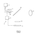
- the camera 8 of the camera 7 and the screen 5 of the positioning device 4 are no longer disposed in the immediate vicinity of the cameras 1 as in the first embodiment .
- the positioning device further comprises two parallel separating blades 20, 21.
- the separating blade 20 extends obliquely in front of the cameras 1 and the telemeter 10 which are adjacent.
- the splitter plate 20 is a spectral splitter arranged in a known manner to transmit the infrared radiation and reflect the visible radiation.
- the separating blade 20 is here at 45 ° with respect to the optical axis of the cameras 1.
- the separating blade 21 is a flux separator which transmits a portion of the visible light flux coming from the separating blade 20 to the screen 5 and which reflects a corresponding proportion of the visible light flux to the camera 8.
- a de-accommodating member 22 is disposed between the separating plates 20 and 21.
- the de-accommodating member 22 is here a lens arranged in a manner known per se for effecting focusing or focusing at infinity.
- the separating blades 20, 21, the de-accommodating member 22 and the screen 5 are substantially aligned on the same axis.
- the operation of the positioning device according to the second embodiment is identical to that of the first embodiment.
- the visible image of the user U is successively reflected in the separating plates 20 and 21 to be captured by the camera 8.
- the screen 5 is visible through the separating blade 21 and the de-accommodating member 22 and is reflected in the separator plate 20 in the direction of the user U. Thanks to the de-accommodating member 22, the U user does not need to accommodate his vision to see the screen 5 clearly.
- the cameras 1 and the rangefinder 10 act directly through the splitter plate 20.
- the device of the second embodiment has the advantage that the width of the screen 5 is not conditioned by the spacing of the cameras 1 as in the first embodiment.
- the separating blade 21 has been removed and the camera 8 has been arranged in the vicinity of the cameras 1 behind the splitter plate 20.
- the separator blade 20 transmitting the infrared radiation, the camera 8 used must be sensitive to this radiation.
- the screen 5 is disposed directly behind the de-accommodating member 22.
- the control unit 9 furthermore incorporates a device for detecting a misalignment between the positioning marks and the eyes of the user and a means of amplification of this defect arranged to magnify the image and the positioning marks to amplify the positioning defect as the user approaches the reference position and thereby facilitate positioning.
- the amplification means is also arranged to amplify lateral and / or height misalignment by correspondingly displacing the displayed images. on the screen relative to the positioning marks.
- a depth positioning defect, detected by the range finder can also be magnified for example by magnifying the images when the user is too close or by reducing the images when the user is too far away.
- the detection and amplification means here are computer programs for image processing.
- the positioning device of the invention is usable for other applications than the capture of images of the eyes for identification purposes, and for example the capture of facial images for a biometric recognition thereof or more simply for an automatic photo booth.
- the processing unit 8 can be replaced by optical means for horizontal inversion of the images such as a lens or a mirror.
- positioning marks have the shape of a cross on the figure 1 it goes without saying that other forms are possible, like circles.
- the positioning marks may further be superimposed on the images by an image processing method, such as overlay or the like, instead of being marked on the screen.
- the spacing of the marks could thus be adapted according to the interocular distance of the user.
- the adaptation of the spacing of the positioning marks with respect to the displayed images is optional and can be omitted, for example, when a variation of the interocular distance has no influence. embarrassing on the positioning.
- the misalignment detection means and the amplification means are usable in all the embodiments and variants. These means can also be omitted.
- optical separators have been described in the form of separator plates, the optical separators can be formed by any other means and in particular prisms.
- the positions of the screen 5 and the camera 8 can be exchanged.
- the positioning device may be devoid of such a member.
- the de-accommodating member 22 may be disposed elsewhere than between the two semi-reflecting strips 20, 21 and in particular between the screen 5 and the semi-reflecting plate 21.
- the de-accommodating member 22 is optional and may be omitted in particular when the optical path between the user and the screen is longer than 35 cm, the length beyond which it is considered that most individuals have no accommodation problems.
- the rangefinder is also optional.
Landscapes
- Engineering & Computer Science (AREA)
- General Physics & Mathematics (AREA)
- Physics & Mathematics (AREA)
- Human Computer Interaction (AREA)
- Multimedia (AREA)
- Theoretical Computer Science (AREA)
- Ophthalmology & Optometry (AREA)
- General Health & Medical Sciences (AREA)
- Health & Medical Sciences (AREA)
- Studio Devices (AREA)
- Image Input (AREA)
- Cameras Adapted For Combination With Other Photographic Or Optical Apparatuses (AREA)
- Eye Examination Apparatus (AREA)
Claims (10)
- Vorrichtung zur Positionierung (4) des Gesichtes eines Anwenders relativ zu einer Vorrichtung zur Bilderfassung (1), dadurch gekennzeichnet, dass die Vorrichtung zur Positionierung ein Bildaufnahmegerät (7), das so ausgebildet ist, dass es horizontal invertierte Bilder liefert, einen Bildschirm (5) zur Anzeige der invertierten Bilder, der am Bildaufnahmegerät angeschlossen ist, und Mittel zum Überlagern der vom Bildschirm angezeigten Bilder mit mindestens einer Positionierungsmarkierung (6) des Anwenders umfasst, wobei die Positionierungsmarkierung und die angezeigten Bilder etwa in derselben Ebene liegen.
- Vorrichtung nach Anspruch 1, dadurch gekennzeichnet, dass die Mittel zur Überlagerung so ausgebildet sind, dass sie zwei Positionierungsmarkierungen (6) zweier Körperelemente des Anwenders überlagern und dass die Vorrichtung ein Messorgan (10) zum Messen eines Abstandes zwischen dem Anwender und dem Bildaufnahmegerät (7), ein Mittel (9), um auf einem Bild des Anwenders bei diesem Abstand einen Abstand zwischen den beiden Körperelementen des Anwenders zu bestimmen und ein Mittel zum Adaptieren einer Abweichung der Positionierungsmarkierungen von den Bildern in Abhängigkeit des ermittelten Abstandes zwischen den Körperelementen des Anwenders umfasst.
- Vorrichtung nach Anspruch 2, dadurch gekennzeichnet, dass die Adaptationsmittel ein Organ zum Steuern (9) einer Vergrößerung der auf dem Bildschirm angezeigten Bilder umfassen.
- Vorrichtung nach Anspruch 1, dadurch gekennzeichnet, dass sie ein Mittel zur Erkennung einer Fehlausrichtung auf den Bildern zwischen den Positionierungsmarkierungen (6) und dem Anwender und ein Mittel zur Verstärkung (9) des Ausrichtungsfehlers auf dem Bildschirm (5) umfasst.
- Vorrichtung nach Anspruch 1, dadurch gekennzeichnet, dass sie eine optische Deakkommodierungs-Vorrichtung (22) umfasst, die vor dem Bildschirm (5) angeordnet ist.
- Vorrichtung zur Erfassung mindestens eines Bildes mindestens eines Auges eines Anwenders, die mindestens eine Erfassungskamera (1) zum Erfassen des Bildes umfasst, dadurch gekennzeichnet, dass die Erfassungsvorrichtung eine Vorrichtung zur Positionierung (4) nach einem der vorhergehenden Ansprüche enthält, wobei der Bildschirm (5) der Vorrichtung zur Positionierung so in der Erfassungsvorrichtung montiert ist, dass, wenn der Anwender den Bildschirm betrachtet, sich das besagte Auge des Anwenders in etwa in der Achse der Erfassungskamera befindet.
- Vorrichtung nach Anspruch 6, dadurch gekennzeichnet, dass der Bildschirm (5) in unmittelbarer Nähe zur Erfassungskamera (1) montiert ist.
- Vorrichtung nach Anspruch 6, dadurch gekennzeichnet, dass sie mindestens einen optischen Strahlteiler (20, 21) enthält, der zwischen dem Bildschirm (5) und der Erfassungskamera (1) angeordnet ist.
- Vorrichtung nach Anspruch 8, dadurch gekennzeichnet, dass sie eine erste Strahlteiler-Scheibe (20) umfasst, die sich schräg vor der Erfassungskamera (1) erstreckt und eine der Erfassungskamera zugewandte nicht reflektierende Seite und eine reflektierende Seite besitzt, die einer reflektierenden Seite einer zweiten Strahlteiler-Scheibe (21) gegenüberliegt, die sich parallel zur ersten Strahlteiler-Scheibe erstreckt und eine dem Bildschirm (5) gegenüberliegende Seite aufweist, wobei das Bildaufnahmegerät (7) der reflektierenden Seite der zweiten Strahlteiler-Scheibe zugewandt ist.
- Verfahren zur Positionierung eines Anwenders relativ zu einer Bilderfassungsvorrichtung, dadurch gekennzeichnet, dass es die Schritte umfasst, Bilder des Anwenders im Wesentlichen kontinuierlich zu filmen, die gefilmten Bilder horizontal zu invertieren und dem Anwender die invertierten Bilder zu präsentieren, wobei diesen mindestens eine Positionierungsmarkierung (6) überlagert wird und wobei die Positionierungsmarkierung und die Bilder in etwa in derselben Ebene dargestellt werden.
Applications Claiming Priority (2)
| Application Number | Priority Date | Filing Date | Title |
|---|---|---|---|
| FR0405649A FR2870948B1 (fr) | 2004-05-25 | 2004-05-25 | Dispositif de positionnement d'un utilisateur par affichage de son image en miroir, dispositif de capture d'images et procede de positionnement correspondants |
| PCT/FR2005/001265 WO2006000670A1 (fr) | 2004-05-25 | 2005-05-20 | Dispositif de positionnement d'un utilisateur par affichage de son image en miroir, dispositif de capture d'images et procede de positionnement correspondants |
Publications (2)
| Publication Number | Publication Date |
|---|---|
| EP1749237A1 EP1749237A1 (de) | 2007-02-07 |
| EP1749237B1 true EP1749237B1 (de) | 2012-10-03 |
Family
ID=34945603
Family Applications (1)
| Application Number | Title | Priority Date | Filing Date |
|---|---|---|---|
| EP05773072A Expired - Lifetime EP1749237B1 (de) | 2004-05-25 | 2005-05-20 | Vorrichtung zur Positionierung eines Anwenders mittels Anzeige seines Bildes in einem Spiegel und entsprechende Bilderfassungsvorrichtung und Positionierungsverfahren |
Country Status (6)
| Country | Link |
|---|---|
| US (1) | US7978883B2 (de) |
| EP (1) | EP1749237B1 (de) |
| JP (1) | JP4829221B2 (de) |
| ES (1) | ES2392555T3 (de) |
| FR (1) | FR2870948B1 (de) |
| WO (1) | WO2006000670A1 (de) |
Families Citing this family (39)
| Publication number | Priority date | Publication date | Assignee | Title |
|---|---|---|---|---|
| US8260008B2 (en) | 2005-11-11 | 2012-09-04 | Eyelock, Inc. | Methods for performing biometric recognition of a human eye and corroboration of same |
| US8364646B2 (en) | 2006-03-03 | 2013-01-29 | Eyelock, Inc. | Scalable searching of biometric databases using dynamic selection of data subsets |
| US8604901B2 (en) * | 2006-06-27 | 2013-12-10 | Eyelock, Inc. | Ensuring the provenance of passengers at a transportation facility |
| EP2076871A4 (de) | 2006-09-22 | 2015-09-16 | Eyelock Inc | Kompaktes biometrisches erfassungssystem und entsprechendes verfahren |
| WO2008042879A1 (en) | 2006-10-02 | 2008-04-10 | Global Rainmakers, Inc. | Fraud resistant biometric financial transaction system and method |
| US9053323B2 (en) * | 2007-04-13 | 2015-06-09 | Hewlett-Packard Development Company, L.P. | Trusted component update system and method |
| WO2008131201A1 (en) | 2007-04-19 | 2008-10-30 | Global Rainmakers, Inc. | Method and system for biometric recognition |
| US8953849B2 (en) | 2007-04-19 | 2015-02-10 | Eyelock, Inc. | Method and system for biometric recognition |
| US8212870B2 (en) | 2007-09-01 | 2012-07-03 | Hanna Keith J | Mirror system and method for acquiring biometric data |
| US9117119B2 (en) | 2007-09-01 | 2015-08-25 | Eyelock, Inc. | Mobile identity platform |
| US9036871B2 (en) | 2007-09-01 | 2015-05-19 | Eyelock, Inc. | Mobility identity platform |
| US8553948B2 (en) | 2007-09-01 | 2013-10-08 | Eyelock, Inc. | System and method for iris data acquisition for biometric identification |
| US9002073B2 (en) | 2007-09-01 | 2015-04-07 | Eyelock, Inc. | Mobile identity platform |
| CN101409784A (zh) | 2007-10-10 | 2009-04-15 | 联想(北京)有限公司 | 摄像装置及信息提示装置 |
| WO2009158662A2 (en) | 2008-06-26 | 2009-12-30 | Global Rainmakers, Inc. | Method of reducing visibility of illimination while acquiring high quality imagery |
| US8195044B2 (en) | 2009-03-30 | 2012-06-05 | Eyelock Inc. | Biometric camera mount system |
| CN101877764B (zh) * | 2009-04-29 | 2012-05-30 | 鸿富锦精密工业(深圳)有限公司 | 拍摄系统及使用该拍摄系统进行辅助构图的方法 |
| US10043229B2 (en) | 2011-01-26 | 2018-08-07 | Eyelock Llc | Method for confirming the identity of an individual while shielding that individual's personal data |
| RU2589859C2 (ru) | 2011-02-17 | 2016-07-10 | АЙЛОК ЭлЭлСи | Эффективный способ и система для получения данных изображения сцены и изображения радужной оболочки с использованием одного датчика |
| US20120268241A1 (en) | 2011-04-19 | 2012-10-25 | Eyelock Inc. | Biometric chain of provenance |
| RU2623795C2 (ru) | 2011-08-22 | 2017-06-29 | АЙЛОК ЭлЭлСи | Системы и способы для захвата безартефактных изображений |
| KR102037017B1 (ko) * | 2012-02-27 | 2019-11-26 | 오비오 테크놀로지즈, 인크. | 360°비디오 카메라 영상 시스템 |
| JP2013178702A (ja) * | 2012-02-29 | 2013-09-09 | Azbil Corp | 顔認証センサ |
| US9495526B2 (en) | 2013-03-15 | 2016-11-15 | Eyelock Llc | Efficient prevention of fraud |
| JP2015012304A (ja) * | 2013-06-26 | 2015-01-19 | ソニー株式会社 | 画像処理装置、画像処理方法、及び、プログラム |
| EP3087533A4 (de) | 2013-12-23 | 2017-09-20 | Eyelock Llc | Verfahren und vorrichtung für leistungseffiziente iriserkennung |
| CN105981047A (zh) | 2014-01-06 | 2016-09-28 | 眼锁有限责任公司 | 用于重复虹膜识别的方法和设备 |
| EP3192009A4 (de) | 2014-09-12 | 2018-04-25 | Eyelock Llc | Verfahren und vorrichtung zum richten des blicks eines benutzers in einem iriserkennungssystem |
| US10332113B2 (en) | 2014-11-19 | 2019-06-25 | Eyelock Llc | Model-based prediction of an optimal convenience metric for authorizing transactions |
| US10074011B2 (en) | 2015-01-20 | 2018-09-11 | Eyelock Llc | Lens system for high quality visible image acquisition and infra-red iris image acquisition |
| CN107580767B (zh) | 2015-03-12 | 2020-12-29 | 眼锁有限责任公司 | 使用生物特征来管理网络活动的方法和系统 |
| CN105611153B (zh) * | 2015-12-21 | 2019-09-24 | 联想(北京)有限公司 | 图像处理方法和电子设备 |
| US10311299B2 (en) | 2015-12-21 | 2019-06-04 | Eyelock Llc | Reflected optic camera module for iris recognition in a computing device |
| WO2017201147A2 (en) | 2016-05-18 | 2017-11-23 | Eyelock, Llc | Iris recognition methods and systems based on an iris stochastic texture model |
| US10121236B2 (en) * | 2016-10-26 | 2018-11-06 | Himax Technologies Limited | Automatic alignment apparatus and associated method |
| DE102017103884A1 (de) | 2017-02-24 | 2018-08-30 | Osram Opto Semiconductors Gmbh | Beleuchtungseinrichtung, elektronisches Gerät mit einer Beleuchtungseinrichtung und Verwendung einer Beleuchtungseinrichtung |
| WO2018156726A1 (en) | 2017-02-24 | 2018-08-30 | Eyelock, Llc | Systems and methods for providing illumination for iris biometric acquisition |
| CA3015802C (en) | 2017-08-31 | 2021-06-22 | Eyelock, Llc | Systems and methods of biometric acquistion using positive optical distortion |
| EP3669748A1 (de) | 2018-12-19 | 2020-06-24 | Koninklijke Philips N.V. | Spiegelanordnung |
Family Cites Families (12)
| Publication number | Priority date | Publication date | Assignee | Title |
|---|---|---|---|---|
| JP3164247B2 (ja) * | 1992-06-15 | 2001-05-08 | 富士写真フイルム株式会社 | 証明写真撮影用カメラ |
| JP3376069B2 (ja) * | 1993-12-30 | 2003-02-10 | キヤノン株式会社 | 眼科装置 |
| US5572596A (en) * | 1994-09-02 | 1996-11-05 | David Sarnoff Research Center, Inc. | Automated, non-invasive iris recognition system and method |
| US6289113B1 (en) * | 1998-11-25 | 2001-09-11 | Iridian Technologies, Inc. | Handheld iris imaging apparatus and method |
| US7277561B2 (en) * | 2000-10-07 | 2007-10-02 | Qritek Co., Ltd. | Iris identification |
| JP4438214B2 (ja) * | 2000-11-02 | 2010-03-24 | 沖電気工業株式会社 | 撮影装置 |
| JP2002175538A (ja) * | 2000-12-08 | 2002-06-21 | Mitsubishi Electric Corp | 似顔絵生成装置及び似顔絵生成方法及び似顔絵生成プログラムを記録した記録媒体及び通信用端末及び通信用端末による通信方法 |
| DE20101349U1 (de) | 2001-01-25 | 2001-05-03 | WINCOR NIXDORF GmbH & Co. KG, 33106 Paderborn | Selbstbedienungsterminal mit Iris- oder Gesichtserkennung |
| US7271839B2 (en) * | 2001-03-15 | 2007-09-18 | Lg Electronics Inc. | Display device of focal angle and focal distance in iris recognition system |
| JP2003021859A (ja) * | 2001-07-09 | 2003-01-24 | Konica Corp | 撮影用ガイド、人物写真撮影装置、人物写真プリント装置 |
| JP2003030659A (ja) * | 2001-07-16 | 2003-01-31 | Matsushita Electric Ind Co Ltd | 虹彩認証装置及び虹彩撮像装置 |
| TWI222029B (en) * | 2001-12-04 | 2004-10-11 | Desun Technology Co Ltd | Two-in-one image display/image capture apparatus and the method thereof and identification system using the same |
-
2004
- 2004-05-25 FR FR0405649A patent/FR2870948B1/fr not_active Expired - Fee Related
-
2005
- 2005-05-20 US US11/579,420 patent/US7978883B2/en active Active
- 2005-05-20 EP EP05773072A patent/EP1749237B1/de not_active Expired - Lifetime
- 2005-05-20 WO PCT/FR2005/001265 patent/WO2006000670A1/fr not_active Ceased
- 2005-05-20 ES ES05773072T patent/ES2392555T3/es not_active Expired - Lifetime
- 2005-05-20 JP JP2007514000A patent/JP4829221B2/ja not_active Expired - Lifetime
Also Published As
| Publication number | Publication date |
|---|---|
| US20070159548A1 (en) | 2007-07-12 |
| JP4829221B2 (ja) | 2011-12-07 |
| US7978883B2 (en) | 2011-07-12 |
| JP2008500571A (ja) | 2008-01-10 |
| FR2870948A1 (fr) | 2005-12-02 |
| FR2870948B1 (fr) | 2006-09-01 |
| WO2006000670A1 (fr) | 2006-01-05 |
| ES2392555T3 (es) | 2012-12-11 |
| EP1749237A1 (de) | 2007-02-07 |
Similar Documents
| Publication | Publication Date | Title |
|---|---|---|
| EP1749237B1 (de) | Vorrichtung zur Positionierung eines Anwenders mittels Anzeige seines Bildes in einem Spiegel und entsprechende Bilderfassungsvorrichtung und Positionierungsverfahren | |
| EP2666071B1 (de) | Verfahren zur feststellung der blickrichtung und vorrichtung dafür | |
| EP1989582B1 (de) | Verfahren und einrichtung zum identifizieren und kalibrieren panoramischer optischer systeme | |
| EP2761366B1 (de) | Mess-verfahren zur bestimmung morpho-geometrischen parameter eines brillen-träger | |
| US20130089240A1 (en) | Handheld iris imager | |
| EP3391810A1 (de) | Vorrichtung zur aufnahme von zahnbildern | |
| EP2791643B1 (de) | System und verfahren zum optischen lesen von markierungen auf der oberfläche einer kontaktlinse | |
| FR2996014A1 (fr) | Procede d'aide a la determination de parametres de vision d'un sujet | |
| EP2098072B1 (de) | Vorrichtung für eine videokonferenz-kommunikation und entsprechendes kommunikationsverfahren | |
| EP1987472B1 (de) | Biodetektor mit kontaktlosem betrieb | |
| EP2611169A1 (de) | Erfassungsvorrichtung für Stereobilder | |
| EP4177839A1 (de) | Verfahren zur bestimmung von kalibrierungsparametern einer bildaufnahmevorrichtung und entsprechendes computerprogrammprodukt | |
| EP2746830B1 (de) | Optische Feineinstellung eines Bilderfassungsgeräts | |
| FR3105049A1 (fr) | Système de contrôle et réglage d’alignement d’alésages | |
| WO1993021819A1 (fr) | Mensurateur a prise de vue pour l'adaptation de lunettes a un patient | |
| EP2998787B1 (de) | Berührungslose vorrichtung und verfahren zur standardisierung der aufnahme von photographien | |
| FR3115120A1 (fr) | Dispositif de réalité augmentée | |
| WO2025219373A1 (fr) | Dispositif portatif de détection d'un faisceau laser, dispositif de visualisation et procédé associé | |
| WO2025163253A1 (fr) | Procédé de commande d'au moins un module caméra, programme d'ordinateur, dispositif de commande et système d'imagerie associés | |
| FR3069681A1 (fr) | Procede et dispositif de capture d'image d'iris | |
| JP3831519B2 (ja) | 1眼レフレックスカメラの測光装置 | |
| EP3982188A1 (de) | Virtual-reality- oder augmented-reality-sichtsystem mit bildsensor des auges | |
| FR2776067A1 (fr) | Systeme de determination et de quantification de l'alignement d'un objet avec une optique de couplage et un dispositif de prise de vues | |
| FR2974438A1 (fr) | Appareil d'aide a la lecture et a la traduction instantanee en vocale | |
| FR3094530A1 (fr) | Dispositif d’acquisition du visage d’un individu |
Legal Events
| Date | Code | Title | Description |
|---|---|---|---|
| PUAI | Public reference made under article 153(3) epc to a published international application that has entered the european phase |
Free format text: ORIGINAL CODE: 0009012 |
|
| 17P | Request for examination filed |
Effective date: 20061024 |
|
| AK | Designated contracting states |
Kind code of ref document: A1 Designated state(s): AT BE BG CH CY CZ DE DK EE ES FI FR GB GR HU IE IS IT LI LT LU MC NL PL PT RO SE SI SK TR |
|
| RIN1 | Information on inventor provided before grant (corrected) |
Inventor name: COTTARD, MARTIN Inventor name: MONTEILLIET, GILLES Inventor name: ROUH, ALAIN Inventor name: FONDEUR, JEAN-CHRISTOPHE |
|
| DAX | Request for extension of the european patent (deleted) | ||
| RAP1 | Party data changed (applicant data changed or rights of an application transferred) |
Owner name: SAGEM SECURITE |
|
| RAP1 | Party data changed (applicant data changed or rights of an application transferred) |
Owner name: MORPHO |
|
| GRAP | Despatch of communication of intention to grant a patent |
Free format text: ORIGINAL CODE: EPIDOSNIGR1 |
|
| RIC1 | Information provided on ipc code assigned before grant |
Ipc: G06K 9/00 20060101ALI20120202BHEP Ipc: G03B 13/10 20060101AFI20120202BHEP |
|
| RTI1 | Title (correction) |
Free format text: DEVICE FOR POSITIONING A USER BY DISPLAYING THE IMAGE THEREOF IN A MIRROR, AND CORRESPONDING IMAGE CAPTURING DEVICE AND POSITIONING METHOD |
|
| GRAS | Grant fee paid |
Free format text: ORIGINAL CODE: EPIDOSNIGR3 |
|
| GRAA | (expected) grant |
Free format text: ORIGINAL CODE: 0009210 |
|
| AK | Designated contracting states |
Kind code of ref document: B1 Designated state(s): AT BE BG CH CY CZ DE DK EE ES FI FR GB GR HU IE IS IT LI LT LU MC NL PL PT RO SE SI SK TR |
|
| REG | Reference to a national code |
Ref country code: GB Ref legal event code: FG4D Free format text: NOT ENGLISH |
|
| REG | Reference to a national code |
Ref country code: CH Ref legal event code: EP Ref country code: AT Ref legal event code: REF Ref document number: 578230 Country of ref document: AT Kind code of ref document: T Effective date: 20121015 |
|
| REG | Reference to a national code |
Ref country code: IE Ref legal event code: FG4D Free format text: LANGUAGE OF EP DOCUMENT: FRENCH |
|
| REG | Reference to a national code |
Ref country code: NL Ref legal event code: T3 |
|
| REG | Reference to a national code |
Ref country code: DE Ref legal event code: R096 Ref document number: 602005036407 Country of ref document: DE Effective date: 20121129 |
|
| REG | Reference to a national code |
Ref country code: ES Ref legal event code: FG2A Ref document number: 2392555 Country of ref document: ES Kind code of ref document: T3 Effective date: 20121211 |
|
| REG | Reference to a national code |
Ref country code: AT Ref legal event code: MK05 Ref document number: 578230 Country of ref document: AT Kind code of ref document: T Effective date: 20121003 |
|
| PG25 | Lapsed in a contracting state [announced via postgrant information from national office to epo] |
Ref country code: SI Free format text: LAPSE BECAUSE OF FAILURE TO SUBMIT A TRANSLATION OF THE DESCRIPTION OR TO PAY THE FEE WITHIN THE PRESCRIBED TIME-LIMIT Effective date: 20121003 |
|
| REG | Reference to a national code |
Ref country code: LT Ref legal event code: MG4D |
|
| PG25 | Lapsed in a contracting state [announced via postgrant information from national office to epo] |
Ref country code: SE Free format text: LAPSE BECAUSE OF FAILURE TO SUBMIT A TRANSLATION OF THE DESCRIPTION OR TO PAY THE FEE WITHIN THE PRESCRIBED TIME-LIMIT Effective date: 20121003 Ref country code: FI Free format text: LAPSE BECAUSE OF FAILURE TO SUBMIT A TRANSLATION OF THE DESCRIPTION OR TO PAY THE FEE WITHIN THE PRESCRIBED TIME-LIMIT Effective date: 20121003 Ref country code: LT Free format text: LAPSE BECAUSE OF FAILURE TO SUBMIT A TRANSLATION OF THE DESCRIPTION OR TO PAY THE FEE WITHIN THE PRESCRIBED TIME-LIMIT Effective date: 20121003 Ref country code: IS Free format text: LAPSE BECAUSE OF FAILURE TO SUBMIT A TRANSLATION OF THE DESCRIPTION OR TO PAY THE FEE WITHIN THE PRESCRIBED TIME-LIMIT Effective date: 20130203 |
|
| PG25 | Lapsed in a contracting state [announced via postgrant information from national office to epo] |
Ref country code: GR Free format text: LAPSE BECAUSE OF FAILURE TO SUBMIT A TRANSLATION OF THE DESCRIPTION OR TO PAY THE FEE WITHIN THE PRESCRIBED TIME-LIMIT Effective date: 20130104 Ref country code: PT Free format text: LAPSE BECAUSE OF FAILURE TO SUBMIT A TRANSLATION OF THE DESCRIPTION OR TO PAY THE FEE WITHIN THE PRESCRIBED TIME-LIMIT Effective date: 20130204 Ref country code: PL Free format text: LAPSE BECAUSE OF FAILURE TO SUBMIT A TRANSLATION OF THE DESCRIPTION OR TO PAY THE FEE WITHIN THE PRESCRIBED TIME-LIMIT Effective date: 20121003 Ref country code: CY Free format text: LAPSE BECAUSE OF FAILURE TO SUBMIT A TRANSLATION OF THE DESCRIPTION OR TO PAY THE FEE WITHIN THE PRESCRIBED TIME-LIMIT Effective date: 20121003 |
|
| PG25 | Lapsed in a contracting state [announced via postgrant information from national office to epo] |
Ref country code: AT Free format text: LAPSE BECAUSE OF FAILURE TO SUBMIT A TRANSLATION OF THE DESCRIPTION OR TO PAY THE FEE WITHIN THE PRESCRIBED TIME-LIMIT Effective date: 20121003 |
|
| PG25 | Lapsed in a contracting state [announced via postgrant information from national office to epo] |
Ref country code: CZ Free format text: LAPSE BECAUSE OF FAILURE TO SUBMIT A TRANSLATION OF THE DESCRIPTION OR TO PAY THE FEE WITHIN THE PRESCRIBED TIME-LIMIT Effective date: 20121003 Ref country code: DK Free format text: LAPSE BECAUSE OF FAILURE TO SUBMIT A TRANSLATION OF THE DESCRIPTION OR TO PAY THE FEE WITHIN THE PRESCRIBED TIME-LIMIT Effective date: 20121003 Ref country code: SK Free format text: LAPSE BECAUSE OF FAILURE TO SUBMIT A TRANSLATION OF THE DESCRIPTION OR TO PAY THE FEE WITHIN THE PRESCRIBED TIME-LIMIT Effective date: 20121003 Ref country code: EE Free format text: LAPSE BECAUSE OF FAILURE TO SUBMIT A TRANSLATION OF THE DESCRIPTION OR TO PAY THE FEE WITHIN THE PRESCRIBED TIME-LIMIT Effective date: 20121003 Ref country code: BG Free format text: LAPSE BECAUSE OF FAILURE TO SUBMIT A TRANSLATION OF THE DESCRIPTION OR TO PAY THE FEE WITHIN THE PRESCRIBED TIME-LIMIT Effective date: 20130103 |
|
| PLBE | No opposition filed within time limit |
Free format text: ORIGINAL CODE: 0009261 |
|
| STAA | Information on the status of an ep patent application or granted ep patent |
Free format text: STATUS: NO OPPOSITION FILED WITHIN TIME LIMIT |
|
| PG25 | Lapsed in a contracting state [announced via postgrant information from national office to epo] |
Ref country code: RO Free format text: LAPSE BECAUSE OF FAILURE TO SUBMIT A TRANSLATION OF THE DESCRIPTION OR TO PAY THE FEE WITHIN THE PRESCRIBED TIME-LIMIT Effective date: 20121003 |
|
| 26N | No opposition filed |
Effective date: 20130704 |
|
| REG | Reference to a national code |
Ref country code: FR Ref legal event code: CA Effective date: 20130917 |
|
| REG | Reference to a national code |
Ref country code: DE Ref legal event code: R097 Ref document number: 602005036407 Country of ref document: DE Effective date: 20130704 |
|
| BERE | Be: lapsed |
Owner name: MORPHO Effective date: 20130531 |
|
| PG25 | Lapsed in a contracting state [announced via postgrant information from national office to epo] |
Ref country code: MC Free format text: LAPSE BECAUSE OF FAILURE TO SUBMIT A TRANSLATION OF THE DESCRIPTION OR TO PAY THE FEE WITHIN THE PRESCRIBED TIME-LIMIT Effective date: 20121003 |
|
| REG | Reference to a national code |
Ref country code: CH Ref legal event code: PL |
|
| PG25 | Lapsed in a contracting state [announced via postgrant information from national office to epo] |
Ref country code: LI Free format text: LAPSE BECAUSE OF NON-PAYMENT OF DUE FEES Effective date: 20130531 Ref country code: CH Free format text: LAPSE BECAUSE OF NON-PAYMENT OF DUE FEES Effective date: 20130531 |
|
| REG | Reference to a national code |
Ref country code: IE Ref legal event code: MM4A |
|
| PG25 | Lapsed in a contracting state [announced via postgrant information from national office to epo] |
Ref country code: BE Free format text: LAPSE BECAUSE OF NON-PAYMENT OF DUE FEES Effective date: 20130531 |
|
| PG25 | Lapsed in a contracting state [announced via postgrant information from national office to epo] |
Ref country code: IE Free format text: LAPSE BECAUSE OF NON-PAYMENT OF DUE FEES Effective date: 20130520 |
|
| PG25 | Lapsed in a contracting state [announced via postgrant information from national office to epo] |
Ref country code: TR Free format text: LAPSE BECAUSE OF FAILURE TO SUBMIT A TRANSLATION OF THE DESCRIPTION OR TO PAY THE FEE WITHIN THE PRESCRIBED TIME-LIMIT Effective date: 20121003 |
|
| PG25 | Lapsed in a contracting state [announced via postgrant information from national office to epo] |
Ref country code: HU Free format text: LAPSE BECAUSE OF FAILURE TO SUBMIT A TRANSLATION OF THE DESCRIPTION OR TO PAY THE FEE WITHIN THE PRESCRIBED TIME-LIMIT; INVALID AB INITIO Effective date: 20050520 Ref country code: LU Free format text: LAPSE BECAUSE OF NON-PAYMENT OF DUE FEES Effective date: 20130520 |
|
| REG | Reference to a national code |
Ref country code: FR Ref legal event code: PLFP Year of fee payment: 12 |
|
| REG | Reference to a national code |
Ref country code: FR Ref legal event code: PLFP Year of fee payment: 13 |
|
| REG | Reference to a national code |
Ref country code: FR Ref legal event code: PLFP Year of fee payment: 14 |
|
| REG | Reference to a national code |
Ref country code: DE Ref legal event code: R081 Ref document number: 602005036407 Country of ref document: DE Owner name: IDEMIA IDENTITY & SECURITY FRANCE, FR Free format text: FORMER OWNER: MORPHO, PARIS, FR Ref country code: DE Ref legal event code: R081 Ref document number: 602005036407 Country of ref document: DE Owner name: IDEMIA PUBLIC SECURITY FRANCE, FR Free format text: FORMER OWNER: MORPHO, PARIS, FR |
|
| P01 | Opt-out of the competence of the unified patent court (upc) registered |
Effective date: 20230428 |
|
| REG | Reference to a national code |
Ref country code: NL Ref legal event code: HC Owner name: IDEMIA IDENTITY & SECURITY FRANCE; FR Free format text: DETAILS ASSIGNMENT: CHANGE OF OWNER(S), CHANGE OF OWNER(S) NAME; FORMER OWNER NAME: MORPHO Effective date: 20240305 |
|
| REG | Reference to a national code |
Ref country code: ES Ref legal event code: PC2A Owner name: IDEMIA IDENTITY & SECURITY FRANCE Effective date: 20240429 |
|
| PGFP | Annual fee paid to national office [announced via postgrant information from national office to epo] |
Ref country code: NL Payment date: 20240418 Year of fee payment: 20 |
|
| PGFP | Annual fee paid to national office [announced via postgrant information from national office to epo] |
Ref country code: GB Payment date: 20240419 Year of fee payment: 20 |
|
| PGFP | Annual fee paid to national office [announced via postgrant information from national office to epo] |
Ref country code: DE Payment date: 20240418 Year of fee payment: 20 |
|
| PGFP | Annual fee paid to national office [announced via postgrant information from national office to epo] |
Ref country code: ES Payment date: 20240603 Year of fee payment: 20 |
|
| PGFP | Annual fee paid to national office [announced via postgrant information from national office to epo] |
Ref country code: IT Payment date: 20240418 Year of fee payment: 20 Ref country code: FR Payment date: 20240418 Year of fee payment: 20 |
|
| REG | Reference to a national code |
Ref country code: DE Ref legal event code: R071 Ref document number: 602005036407 Country of ref document: DE |
|
| REG | Reference to a national code |
Ref country code: NL Ref legal event code: MK Effective date: 20250519 |
|
| REG | Reference to a national code |
Ref country code: ES Ref legal event code: FD2A Effective date: 20250527 |
|
| REG | Reference to a national code |
Ref country code: DE Ref legal event code: R081 Ref document number: 602005036407 Country of ref document: DE Owner name: IDEMIA PUBLIC SECURITY FRANCE, FR Free format text: FORMER OWNER: IDEMIA IDENTITY & SECURITY FRANCE, COURBEVOIE, FR |
|
| REG | Reference to a national code |
Ref country code: GB Ref legal event code: PE20 Expiry date: 20250519 |
|
| PG25 | Lapsed in a contracting state [announced via postgrant information from national office to epo] |
Ref country code: ES Free format text: LAPSE BECAUSE OF EXPIRATION OF PROTECTION Effective date: 20250521 Ref country code: GB Free format text: LAPSE BECAUSE OF EXPIRATION OF PROTECTION Effective date: 20250519 |
|
| REG | Reference to a national code |
Ref country code: GB Ref legal event code: 732E Free format text: REGISTERED BETWEEN 20251002 AND 20251008 |