EP1749491A2 - Dispositif de traitement de corps vertébraux - Google Patents
Dispositif de traitement de corps vertébraux Download PDFInfo
- Publication number
- EP1749491A2 EP1749491A2 EP06016231A EP06016231A EP1749491A2 EP 1749491 A2 EP1749491 A2 EP 1749491A2 EP 06016231 A EP06016231 A EP 06016231A EP 06016231 A EP06016231 A EP 06016231A EP 1749491 A2 EP1749491 A2 EP 1749491A2
- Authority
- EP
- European Patent Office
- Prior art keywords
- biopsy
- cement
- trocar
- cannula
- vertebral body
- Prior art date
- Legal status (The legal status is an assumption and is not a legal conclusion. Google has not performed a legal analysis and makes no representation as to the accuracy of the status listed.)
- Withdrawn
Links
- 239000004568 cement Substances 0.000 claims abstract description 131
- 238000001574 biopsy Methods 0.000 claims abstract description 130
- 239000002639 bone cement Substances 0.000 claims abstract description 73
- 238000000034 method Methods 0.000 claims description 46
- 241001631457 Cannula Species 0.000 claims description 18
- 210000000988 bone and bone Anatomy 0.000 claims description 9
- 239000000463 material Substances 0.000 claims description 6
- 229910000831 Steel Inorganic materials 0.000 claims description 4
- 239000010959 steel Substances 0.000 claims description 4
- 239000007788 liquid Substances 0.000 description 6
- 210000000115 thoracic cavity Anatomy 0.000 description 3
- 238000013459 approach Methods 0.000 description 2
- 238000011161 development Methods 0.000 description 2
- 230000018109 developmental process Effects 0.000 description 2
- 208000037265 diseases, disorders, signs and symptoms Diseases 0.000 description 2
- 210000005036 nerve Anatomy 0.000 description 2
- 229920003229 poly(methyl methacrylate) Polymers 0.000 description 2
- 239000004926 polymethyl methacrylate Substances 0.000 description 2
- LWIHDJKSTIGBAC-UHFFFAOYSA-K tripotassium phosphate Chemical compound [K+].[K+].[K+].[O-]P([O-])([O-])=O LWIHDJKSTIGBAC-UHFFFAOYSA-K 0.000 description 2
- 208000005189 Embolism Diseases 0.000 description 1
- 206010033892 Paraplegia Diseases 0.000 description 1
- 238000004873 anchoring Methods 0.000 description 1
- 238000010009 beating Methods 0.000 description 1
- 238000007796 conventional method Methods 0.000 description 1
- 201000010099 disease Diseases 0.000 description 1
- 208000035475 disorder Diseases 0.000 description 1
- 230000002349 favourable effect Effects 0.000 description 1
- 238000005429 filling process Methods 0.000 description 1
- 201000011066 hemangioma Diseases 0.000 description 1
- 238000010562 histological examination Methods 0.000 description 1
- 238000002347 injection Methods 0.000 description 1
- 239000007924 injection Substances 0.000 description 1
- 238000003780 insertion Methods 0.000 description 1
- 230000037431 insertion Effects 0.000 description 1
- 210000004072 lung Anatomy 0.000 description 1
- 230000001394 metastastic effect Effects 0.000 description 1
- 206010061289 metastatic neoplasm Diseases 0.000 description 1
- 230000007971 neurological deficit Effects 0.000 description 1
- 230000001009 osteoporotic effect Effects 0.000 description 1
- 229910000160 potassium phosphate Inorganic materials 0.000 description 1
- 235000011009 potassium phosphates Nutrition 0.000 description 1
- 238000012545 processing Methods 0.000 description 1
- 230000000087 stabilizing effect Effects 0.000 description 1
- 230000007704 transition Effects 0.000 description 1
Images



Classifications
-
- A—HUMAN NECESSITIES
- A61—MEDICAL OR VETERINARY SCIENCE; HYGIENE
- A61B—DIAGNOSIS; SURGERY; IDENTIFICATION
- A61B17/00—Surgical instruments, devices or methods
- A61B17/56—Surgical instruments or methods for treatment of bones or joints; Devices specially adapted therefor
- A61B17/58—Surgical instruments or methods for treatment of bones or joints; Devices specially adapted therefor for osteosynthesis, e.g. bone plates, screws or setting implements
- A61B17/88—Osteosynthesis instruments; Methods or means for implanting or extracting internal or external fixation devices
- A61B17/8802—Equipment for handling bone cement or other fluid fillers
- A61B17/8805—Equipment for handling bone cement or other fluid fillers for introducing fluid filler into bone or extracting it
- A61B17/8822—Equipment for handling bone cement or other fluid fillers for introducing fluid filler into bone or extracting it characterised by means facilitating expulsion of fluid from the introducer, e.g. a screw pump plunger, hydraulic force transmissions, application of vibrations or a vacuum
-
- A—HUMAN NECESSITIES
- A61—MEDICAL OR VETERINARY SCIENCE; HYGIENE
- A61B—DIAGNOSIS; SURGERY; IDENTIFICATION
- A61B17/00—Surgical instruments, devices or methods
- A61B17/16—Instruments for performing osteoclasis; Drills or chisels for bones; Trepans
- A61B17/1604—Chisels; Rongeurs; Punches; Stamps
-
- A—HUMAN NECESSITIES
- A61—MEDICAL OR VETERINARY SCIENCE; HYGIENE
- A61B—DIAGNOSIS; SURGERY; IDENTIFICATION
- A61B17/00—Surgical instruments, devices or methods
- A61B17/16—Instruments for performing osteoclasis; Drills or chisels for bones; Trepans
- A61B17/1662—Instruments for performing osteoclasis; Drills or chisels for bones; Trepans for particular parts of the body
- A61B17/1671—Instruments for performing osteoclasis; Drills or chisels for bones; Trepans for particular parts of the body for the spine
-
- A—HUMAN NECESSITIES
- A61—MEDICAL OR VETERINARY SCIENCE; HYGIENE
- A61B—DIAGNOSIS; SURGERY; IDENTIFICATION
- A61B17/00—Surgical instruments, devices or methods
- A61B17/34—Trocars; Puncturing needles
- A61B17/3472—Trocars; Puncturing needles for bones, e.g. intraosseus injections
-
- A—HUMAN NECESSITIES
- A61—MEDICAL OR VETERINARY SCIENCE; HYGIENE
- A61B—DIAGNOSIS; SURGERY; IDENTIFICATION
- A61B17/00—Surgical instruments, devices or methods
- A61B17/56—Surgical instruments or methods for treatment of bones or joints; Devices specially adapted therefor
- A61B17/58—Surgical instruments or methods for treatment of bones or joints; Devices specially adapted therefor for osteosynthesis, e.g. bone plates, screws or setting implements
- A61B17/88—Osteosynthesis instruments; Methods or means for implanting or extracting internal or external fixation devices
- A61B17/8802—Equipment for handling bone cement or other fluid fillers
- A61B17/8805—Equipment for handling bone cement or other fluid fillers for introducing fluid filler into bone or extracting it
- A61B17/8819—Equipment for handling bone cement or other fluid fillers for introducing fluid filler into bone or extracting it characterised by the introducer proximal part, e.g. cannula handle, or by parts which are inserted inside each other, e.g. stylet and cannula
-
- A—HUMAN NECESSITIES
- A61—MEDICAL OR VETERINARY SCIENCE; HYGIENE
- A61B—DIAGNOSIS; SURGERY; IDENTIFICATION
- A61B10/00—Instruments for taking body samples for diagnostic purposes; Other methods or instruments for diagnosis, e.g. for vaccination diagnosis, sex determination or ovulation-period determination; Throat striking implements
- A61B10/02—Instruments for taking cell samples or for biopsy
- A61B10/0233—Pointed or sharp biopsy instruments
- A61B10/025—Pointed or sharp biopsy instruments for taking bone, bone marrow or cartilage samples
-
- A—HUMAN NECESSITIES
- A61—MEDICAL OR VETERINARY SCIENCE; HYGIENE
- A61B—DIAGNOSIS; SURGERY; IDENTIFICATION
- A61B17/00—Surgical instruments, devices or methods
- A61B17/00234—Surgical instruments, devices or methods for minimally invasive surgery
- A61B2017/00238—Type of minimally invasive operation
- A61B2017/00261—Discectomy
-
- A—HUMAN NECESSITIES
- A61—MEDICAL OR VETERINARY SCIENCE; HYGIENE
- A61B—DIAGNOSIS; SURGERY; IDENTIFICATION
- A61B90/00—Instruments, implements or accessories specially adapted for surgery or diagnosis and not covered by any of the groups A61B1/00 - A61B50/00, e.g. for luxation treatment or for protecting wound edges
- A61B90/36—Image-producing devices or illumination devices not otherwise provided for
- A61B90/37—Surgical systems with images on a monitor during operation
- A61B2090/376—Surgical systems with images on a monitor during operation using X-rays, e.g. fluoroscopy
-
- A—HUMAN NECESSITIES
- A61—MEDICAL OR VETERINARY SCIENCE; HYGIENE
- A61B—DIAGNOSIS; SURGERY; IDENTIFICATION
- A61B34/00—Computer-aided surgery; Manipulators or robots specially adapted for use in surgery
- A61B34/20—Surgical navigation systems; Devices for tracking or guiding surgical instruments, e.g. for frameless stereotaxis
-
- A—HUMAN NECESSITIES
- A61—MEDICAL OR VETERINARY SCIENCE; HYGIENE
- A61F—FILTERS IMPLANTABLE INTO BLOOD VESSELS; PROSTHESES; DEVICES PROVIDING PATENCY TO, OR PREVENTING COLLAPSING OF, TUBULAR STRUCTURES OF THE BODY, e.g. STENTS; ORTHOPAEDIC, NURSING OR CONTRACEPTIVE DEVICES; FOMENTATION; TREATMENT OR PROTECTION OF EYES OR EARS; BANDAGES, DRESSINGS OR ABSORBENT PADS; FIRST-AID KITS
- A61F2/00—Filters implantable into blood vessels; Prostheses, i.e. artificial substitutes or replacements for parts of the body; Appliances for connecting them with the body; Devices providing patency to, or preventing collapsing of, tubular structures of the body, e.g. stents
- A61F2/02—Prostheses implantable into the body
- A61F2/30—Joints
- A61F2/44—Joints for the spine, e.g. vertebrae, spinal discs
Definitions
- the invention relates to a method and a device for the treatment of vertebral bodies.
- Vertebral body diseases such as osteoporotic vertebral body fractures, metastatic vertebral bodies or hemangioma vertebrae are treated by known minimally invasive cementing techniques which stabilize the pathologically altered vertebral body and alleviate pain associated with the disorders.
- the conventional method of vertebroplasty involves the percutaneous dorsal introduction of liquid bone cement under pressure into the pathologically altered vertebral body, which is optionally repositioned by appropriate storage of the patient. Due to the liquid cement and the use of pressure, however, this method regularly leads to leakage of bone cement. If this enters the spinal canal, neurological deficits up to paraplegia are the result. Furthermore, cement lung embolisms may occur if the bone cement enters the venous system.
- the invention is therefore based on the object to provide a method and an apparatus with which an improved implementation of the vertebroplasty method is possible.
- the object is achieved by the inventive method for the treatment of vertebral bodies according to claim 1 and the inventive Apparatus for carrying out the method according to claim 10.
- the method according to the invention for treating a vertebral body has the following steps: First, a trocar sleeve is inserted through the skin into the vertebral body with the aid of a trocar. The trocar is then removed. Subsequently, a biopsy and cement cannula is inserted into the trocar sleeve, the cancellous bone is drawn into the biopsy and cement cannula and the biopsy and cement cannula are removed from the trocar sleeve. A biopsy and cement cannula filled with bone cement is then inserted into the trocar sleeve. Finally, the bone cement is introduced into the vertebral body by inserting a plug into the biopsy and cement cannula, which pushes out the bone cement located in the biopsy and cement cannula at the distal end of the biopsy and cement cannula.
- the advantage of this method is that in contrast to the introduction of the liquid bone cement with a syringe in which the bone cement is pressed with pressure through a narrow needle, in this case can be introduced into the vertebral body by targeted metered insertion using the Stopfers bone cement, without Having to force the bone cement into the vertebral body with high pressure, so that the risk of leakage of bone cement into the spinal canal or the venous system is reduced.
- removing at least parts of the spongiosa by means of a biopsy and cement cannula, a cavity is created in the vertebral body, in which subsequently the bone cement can be filled.
- the creation of a cavity in which at least parts of the cancellous bone is pulled out of the vertebral body has the advantage that no pressure has to be exerted on the vertebral body when filling the bone cement. Furthermore, diseased parts of cancellous bone can be completely removed and do not remain in the vertebral body. In particular, a good distribution of the bone cement in the area of the vertebral body with good biomechanical anchoring is achieved by first producing a cavity.
- the bone cement is introduced into the vertebral body in a viscous state.
- the processing of liquid bone cement under high pressure represents the main risk in the known methods of vertebroplasty, since the liquid bone cement is particularly easy to escape into the spinal canal or the venous system.
- the use of a biopsy and cement cannula, from which the bone cement is implanted with the aid of a stuffer allows the use of viscous bone cement.
- the viscous bone cement can be ideally distributed in the vertebral body and there is a very low risk of complications with regard to the cement outlet from the vertebral body.
- two biopsy and cement cannulas are introduced through two trocar sleeves into the vertebral body.
- two trocar sleeves are symmetrically introduced into the vertebral body.
- the at least one trocar sleeve transpedicular be introduced into the vertebral body, as this allows the most favorable access to the vertebral body and the interior of the vertebral body. In particular, this damage to the nerve root, which may possibly occur in an extra-pedicular access, avoided.
- the tamper preferably has a marking which corresponds to the volume of bone cement to be introduced into the vertebral body. If the pusher is introduced step by step into the biopsy and cement cannula, it can thus be determined from the marking arranged on the outer circumference of the stuffer, how much bone cement has already leaked at the distal end of the biopsy and cement cannula and introduced into the vertebral body.
- the method is carried out at least in sections under computer navigation and / or X-ray monitor control in order to track the positioning of the trocar and the trocar sleeve and / or the filling with bone cement and to correct if necessary. Therefore, the entire process preferably takes place under computer navigation and / or X-ray image converter control.
- the device according to the invention for treating a vertebral body in particular for use in the method according to the invention, has at least one biopsy and cement cannula which can be filled with bone cement, and a stuffer, which can be introduced into the biopsy and cement cannula. If the pusher is inserted step by step into the biopsy and cement cannula, the bone cement is carefully pushed out of the biopsy and cement cannula. This makes possible a metered ramming of the bone cement, in which particularly viscous bone cement can be introduced into the interior of the vertebral body, which significantly reduces the risk of cement leakage and associated damage to the introduction of liquid bone cement by means of a forced injection technique.
- the tamper comprises a cylindrical rod having a knob disposed at the proximal end, the length of the cylindrical rod corresponding to the total length of the biopsy and cement cannula.
- the distal end of the cylindrical rod closes with the distal end of the biopsy and cement cannula. Introducing the stuffer beyond the length of the biopsy and cement cannula addition, which could lead to damage to the vertebral body is thus reliably avoided.
- the outer diameter of the cylindrical rod of the stuffer corresponds to the inner diameter of the biopsy and cement cannula.
- the bone cement located in this volume is completely displaced, so that an exact dosage of the amount of bone cement, which is filled into the interior of the vertebral body, is possible.
- no bone cement can escape at the proximal end of the biopsy and cement cannula.
- the exact dosage is further made possible by the fact that the pusher on the outer circumference has markings which correspond to the volume of bone cement to be introduced into the vertebral body.
- the biopsy and cement cannula also has equidistant markings on the outer circumference. These are used to determine how far the biopsy and cement cannula has been inserted into the trocar sleeve to prevent the biopsy and cement cannula is inserted too far into the interior of the vertebral body, which could lead to damage to the vertebral body.
- two biopsy and cement cannulas are used to improve access to the interior of the vertebral body and more uniformly fill a larger area of the interior of the vertebral body with bone cement.
- the device has a trocar and a trocar sleeve. These are preferably matched in their dimensions to the biopsy and cement cannula to allow optimal engagement.
- the trocar preferably has a cylindrical rod with a knob arranged at the proximal end and a trocar tip arranged at the distal end, the length of the cylindrical rod without the trocar tip corresponding to the total length of the trocar sleeve.
- the trocar can thus be inserted into the trocar sleeve so that only the trocar tip protrudes beyond the trocar sleeve. In this condition, the trocar and trocar can be easily inserted into the vertebral body.
- the outer diameter of the cylindrical rod of the trocar corresponds to the inner diameter of the trocar sleeve. This achieves a flush termination between the cylindrical rod of the trocar and the trocar sleeve, thereby including the trocar easier to insert the trocar into the vertebral body.
- the trocar sleeve preferably has markings on the outer circumference. These markings indicate how far the trocar sleeve has been inserted into the vertebral body.
- the inner diameter of the trocar sleeve preferably corresponds to the outer diameter of the biopsy and cement cannula.
- the biopsy and cement cannula can be introduced almost free of play in the trocar sleeve.
- the outer dimensions of the trocar sleeve are kept as low as possible in order to allow as gentle as possible engagement in the vertebral body.
- the trocar is computer navigable. To this end, he has in particular connections for a navigation adapter. This allows a particularly safe introduction of the trocar into the vertebral body, damage to the vertebral body being largely avoided.
- the trocar preferably has a steel ring on its pommel, preferably with connections for an x-ray aiming device. Otherwise, the knob consists of a material which is permeable to X-rays.
- the introduction of the trocar including the trocar sleeve can be done under X-ray image monitor, in particular by using an X-ray target device accurate positioning of the trocar including the trocar sleeve is made possible and damage to the vertebral body can be avoided.
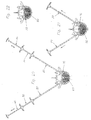
- FIG. 23 shows a side view of a trocar 10 having a cylindrical rod 12 and a knob 16, disposed at the proximal end of the rod 12, of material permeable to X-rays.
- the distal end of the rod 12 has a trocar tip 14.
- the rod 12, including the trocar tip 14, has a length L1 of about 170 mm, with the trocar tip 14 having a length of about 5 mm, and an outer diameter d1 of about 3.5 mm.
- At the transition between the cylindrical rod 12 and the knob 16 are two terminals 17 a, 17 b for navigation adapter, not shown.
- a steel ring 18 which serves as an X-ray target device.
- the trocar 10 is insertable into a trocar sleeve 20, which is shown in a side view in FIG.
- the trocar sleeve 20 has a sleeve 22 and a arranged at the proximal end of the sleeve 22 handle 24 also radiolucent material.
- the sleeve 22 is formed by a cylindrical tube having an outer diameter d2a and an inner diameter d2i. In this case, the inner cavity of the sleeve 22 continues through the handle 24, so that the trocar 10 can be inserted through the handle 24 into the sleeve 22 of the trocar sleeve 20.
- the outer diameter d2a of the sleeve 22 is about 4.2 mm.
- the inner diameter d2i of the sleeve 22 corresponds approximately to the outer diameter d1 of the rod 12 of the trocar 10, but is slightly larger so that the trocar 10 can be inserted, and is about 3.6 mm.
- the total length L2 the trocar sleeve 20 is 165 mm and thus corresponds approximately to the length L1 of the cylindrical rod 12 of the trocar 10 without the length of the trocar tip 14.
- the trocar 10 is inserted through the handle 24 in the trocar sleeve 20 until the knob 16 abuts the handle 24 Thus, only the trocar tip 14 protrudes from the sleeve 22 at the distal end of the trocar sleeve 20.
- circumferential markings 26 are arranged on the outer circumference of the trocar sleeve 20 .
- these markers are arranged equidistantly.
- the distance of the markers 26 is about 10 mm. At these markings 26 can be read when inserting the trocar 10 including the trocar sleeve 20 in the body of the patient and in particular in the vertebral body, as far as the trocar sleeve 20 has already been introduced.
- FIG. 25 shows a side view of a biopsy and cement cannula 30 with a sleeve 32 designed as a cylindrical tube and a handle 34 arranged at its proximal end.
- the biopsy and cement cannula 30 has an overall length L3 of approximately 210 mm.
- the sleeve 32 of the biopsy and cement cannula 30 has an outer diameter d3a and an inner diameter d3i. In this case, the inner cavity of the sleeve 32 continues through the handle 34.
- the outer diameter d3a of the biopsy and cement cannula 30 is about 3.5 mm and corresponds approximately to the inner diameter d2i of the trocar sleeve 20, but is slightly smaller, so that the biopsy and cement cannula 30 can be inserted into the trocar sleeve 20.
- the inner diameter d3i of the biopsy and cement cannula 30 is about 3.1 mm.
- the biopsy and cement cannula 30 has, starting from the arranged at the proximal end of the sleeve 32 handle 34 Markings 36, which are preferably arranged equidistantly. In the present embodiment, the marks 36 are arranged at a distance of about 10 mm. On the basis of the markings 36 it can be read how far the biopsy and cement cannula 30 has been inserted into the trocar sleeve 20.
- the length L3 of the biopsy and cement cannula 30 is significantly greater, for example, about a quarter of the length L3 greater than the length L2 of the trocar sleeve 20.
- the distal end of the sleeve 32 of the biopsy and cement cannula 30 via the distal end of the sleeve 22 of the trocar sleeve 20 may protrude so that the biopsy and cement cannula 30 can be pushed further into the vertebral body as the trocar sleeve 20.
- the markers 36 can be read exactly how far the distal end of the sleeve 32 of Biopsy and cement cannula 30 projects beyond the distal end of the sleeve 22 of the trocar sleeve 20.
- FIG. 26 shows an exemplary embodiment of a stuffer 40, which has a cylindrical rod 42 of length L4 and a knob 44 adjoining the proximal end of the rod 42.
- the rod 42 has an outer diameter d4, which is about 3 mm and thus corresponds approximately to the inner diameter d3i of the biopsy and cement cannula 30, but is slightly smaller, so that the stuffer 40 can be inserted into the biopsy and cement cannula 30.
- the stuffer 40 has on the cylindrical rod 42 circumferential markings 46, which are preferably arranged equidistantly. In the present embodiment, these are arranged starting from the distal end of the rod 42 at a distance of about 70 mm. Due to the outer diameter of about 3 mm thus mark the marks 46 at a distance of 70 mm, a volume of about 0.5 cm 3 . If the pusher 40 in a Inserted bone cement filled biopsy and cement cannula 30, thus, the volume of the exiting at the distal end of the biopsy and cement cannula 30 bone cement can be read using the markers 46.
- the pusher 40 is inserted around two markers 46 in the biopsy and cement cannula 30, when completely filled with bone cement 60 biopsy and cement cannula 30 enters a volume of about 1 cm 3 bone cement 60 at the distal end of the biopsy and cement cannula and the vertebral body.
- the length L4 of the rod 42 is about 210 mm and thus corresponds approximately to the total length L3 of the biopsy and cement cannula 30.
- the stuffer 40 can be fully inserted through the handle 34 into the biopsy and cement cannula 30 until the knob 44 of the stuffer 40 abuts the handle 34 of the biopsy and cement cannula 30, and the distal end of the stuffer 40 terminates flush with the distal end of the biopsy and cement cannula 30 in this position. This ensures that the entire volume of bone cement from the biopsy and cement cannula 30 can be emptied into the interior of the vertebral body.
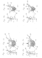
- FIGS. 1a to 4b respectively show a vertebral body 70 with the pedicles 72 in the side view (FIGS. 1a, 2a, 3a and 4a) and a vertical section (FIGS. 1b, 2b, 3b and 4b).
- a lumbar vertebra In the vertebral body 70 shown in Figures 1a to 2b is a lumbar vertebra, while in the figures 3a to 4b, a thoracic vertebra is shown.
- FIGS. 1a to 4b show how the trocar sleeve 20 can be introduced into the vertebral body 70.
- the transpedicular approach is shown in FIGS. 1a, 1b, 3a and 3b, and the extrapedicular approach is shown in FIGS. 2a, 2b, 4a and 4b.
- the trocar sleeve 20 is preferably introduced transpedicularly into the vertebral body 70, since this simplifies access to the vertebral space. In particular, so damage to the nerve root, which may possibly occur in an extra-pedicular access, avoided.
- FIGS. 5 and 6 show the instruments used in a first method step, namely the trocar 10 according to FIG. 23 and the trocar sleeve 20 according to FIG. 24.
- the trocar 10 is inserted into the trocar sleeve 20 until the knob 16 of the trocar 10 on the handle 24 of FIG Trocar sleeve 20 abuts so that the trocar tip 14 protrudes at the distal end of the trocar sleeve 20.
- the trocar 10 including the trocar sleeve 20, as shown in Figure 7, after exposing access to the vertebral body 70, is inserted percutaneously dorsally and transpedicularly into the vertebral body 70 by gentle hammering with a hammer 55 until the distal end of the trocar sleeve 20 is straight into the interior of the vertebral body 70 protrudes.
- This position can be determined by means of a computer navigation and / or an X-ray image monitor, wherein additionally an X-ray target device can be used.
- the complete process is carried out under computer navigation and / or X-ray imager control in order to be able to control each process step.
- Computer navigation is preferably done during deployment of the trocar 10 to monitor proper positioning of the trocar 10. In the further course of the process can be dispensed with. Furthermore, at least one X-ray image monitor is during of the complete procedure. If there is no data for computer navigation, two X-ray imager controls are preferably used.
- a second trocar sleeve 20 is likewise introduced transpedicularly symmetrically with respect to the first trocar sleeve 20.
- FIG. 9 shows how a biopsy and cement cannula 30 according to FIG. 25 is subsequently introduced into each of the trocar sleeves 20.
- the biopsy and cement cannulas 30 are respectively driven through the trocar sleeves 20 to the front edge of the vertebral body 70 on the right and left. It can be read on the markings 36 of the biopsy and cement cannula 30 how far the biopsy and cement cannula 30 has been inserted into the trocar sleeve 20.
- the distal end of the biopsy and cement cannula 30 can be pushed beyond the distal end of the trocar sleeve 20.
- the markings 36 it is checked that the distal end of the biopsy and cement cannula 30 protrudes so far beyond the distal end of the trocar sleeve 20 that it bears almost against the inner surface of the interior of the vertebral body 70 opposite the inlet opening into the interior of the vertebral body 70 ( see Figure 9).
- the two biopsy and cement cannulas 30 thus essentially measure the interior of the vertebral body 70.
- FIG. 10 shows that a syringe 50 is placed on the two handles 34 of the biopsy and cement cannulas 30, with which the cancellous bone 74 is drawn from the interior of the vertebral body 70 while being aspirated by the biopsy and cement cannulas 30 becomes.
- the biopsy and cement cannulas 30 are also pulled out of the trocar sleeves 20 until the distal end of the biopsy and cement cannulas 30 ends approximately with the distal end of the trocar sleeves 20, so that two substantially cylindrical cavities 78 in the interior of the vertebral body 70 arise (see Figure 11).
- the cavities 78 have in a lumbar vertebra, for example, a length of about 25 mm and a diameter of about 3 mm.
- the creation of the cavities 78 facilitates the introduction of the bone cement 60, which can be ideally distributed in the cavities, thereby reducing the risk of bone cement leakage from the vertebral body. Subsequently, the two biopsy and cement cannulas 30 are removed from the trocar sleeves 20 (see Figure 11).
- FIGS. 12 to 14 show that the stuffer 40 according to FIG. 26 is introduced into the biopsy and cement cannula 30 in order to push the obtained biopsy specimen 76 out of the biopsy and cement cannula 30.
- the biopsy specimen 76 may optionally be used for histological examination.
- FIG. 15 shows how bone cement 60 is mixed and drawn into a syringe 50 in a viscous state.
- bone cement 60 any material which is suitable for stabilizing a bone, in particular a vertebral body, is referred to as bone cement 60.
- PMMA polymethyl methacrylate
- potassium phosphate cements can be used as materials.
- the viscous bone cement 60 is filled into the biopsy and cement cannula 30.
- either the biopsy and cement cannula 30, with which the cancellous bone 74 was retracted and which was subsequently cleaned, or an identically formed further biopsy and cement cannula 30 are used.
- bone cement 60 is preferably filled into the syringe 50 until it emerges at the distal end of the biopsy and cement cannula 30 (see FIG. This excess of bone cement 50 is then removed.
- the stuffer 40 is placed on the proximal end of the biopsy and cement cannula 30 (see Fig.
- the biopsy and cement cannula 30 with attached stuffer 40 inserted into the trocar sleeve 20 (see Fig. 18).
- the biopsy and cement cannula 30 can first be inserted into the trocar sleeve 20 and then the stuffer 40 can be placed on the proximal end of the biopsy and cement cannula 30.
- the biopsy and cement cannula 30 is in turn inserted into the trocar sleeve 20 so far that the distal end of the biopsy and cement cannula 30 protrudes beyond the distal end of the trocar sleeve 20 and abuts almost against the opposite inner wall of the vertebral body (see FIG. ,
- FIG. 19 now shows the method step of filling the interior of the vertebral body 70 with bone cement 60.
- the bone cement 60 is filled into the vertebral body 70 by slowly tamping the stuffer 40 into the biopsy and cement cannula 30, while the biopsy and cement cannula 30 is gradually withdrawn from the vertebral body 70.
- the markings 36 on the biopsy and cement cannula 30 it is possible to check how far the biopsy and cement cannula 30 still projects into the interior of the vertebral body 70, while it is possible to check with the markers 46 on the tamper 40 how much bone cement 60 already has was filled in the vertebral body 70.
- the biopsy and cement cannula 30 is pulled out of the trocar sleeve 20 until the distal end of the biopsy and cement cannula 30 terminates with the distal end of the trocar sleeve 20.
- this method step is preferably observed under X-ray image monitor to control the introduction of the bone cement 60 at any time and, if necessary, can stop the filling immediately, if leaks of bone cement 60 are observed from the vertebral body 70.
- bone cement 60 is also introduced into the vertebral body 70 via the second trocar sleeve and the second biopsy and cement cannula 30 (see Fig. 20), while the first biopsy and cement cannula 30 remains in its position. If the required amount of bone cement 60 has been filled in, the trocar sleeves 20, the biopsy and cement cannulas 30 and the tampers 40 remain in the vertebral body 70 until the bone cement 60 has completely set. Subsequently, the tampers 40, the biopsy and cement cannulas 30 and the trocar sleeves 20 are removed one after the other (compare FIG.
- FIG. 22 shows the concluding result of the operation which represents the vertebral body 70 with introduced bone cement 60.
- a cavity 78 can first be produced, in which viscous bone cement 60 can be inserted without pressure from the biopsy and cement cannula 30 with the aid of the stuffer 40, whereby the risk of leakage of bone cement 60 out of the vertebral body 70 becomes clear can be reduced.
Landscapes
- Health & Medical Sciences (AREA)
- Life Sciences & Earth Sciences (AREA)
- Surgery (AREA)
- Orthopedic Medicine & Surgery (AREA)
- Medical Informatics (AREA)
- General Health & Medical Sciences (AREA)
- Biomedical Technology (AREA)
- Heart & Thoracic Surgery (AREA)
- Nuclear Medicine, Radiotherapy & Molecular Imaging (AREA)
- Molecular Biology (AREA)
- Animal Behavior & Ethology (AREA)
- Engineering & Computer Science (AREA)
- Public Health (AREA)
- Veterinary Medicine (AREA)
- Dentistry (AREA)
- Oral & Maxillofacial Surgery (AREA)
- Pathology (AREA)
- Surgical Instruments (AREA)
- Prostheses (AREA)
Applications Claiming Priority (1)
| Application Number | Priority Date | Filing Date | Title |
|---|---|---|---|
| US11/195,898 US8016834B2 (en) | 2005-08-03 | 2005-08-03 | Process and device for treating vertebral bodies |
Publications (2)
| Publication Number | Publication Date |
|---|---|
| EP1749491A2 true EP1749491A2 (fr) | 2007-02-07 |
| EP1749491A3 EP1749491A3 (fr) | 2007-02-21 |
Family
ID=37235991
Family Applications (1)
| Application Number | Title | Priority Date | Filing Date |
|---|---|---|---|
| EP06016231A Withdrawn EP1749491A3 (fr) | 2005-08-03 | 2006-08-03 | Dispositif de traitement de corps vertébraux |
Country Status (3)
| Country | Link |
|---|---|
| US (1) | US8016834B2 (fr) |
| EP (1) | EP1749491A3 (fr) |
| DE (1) | DE202006019988U1 (fr) |
Cited By (1)
| Publication number | Priority date | Publication date | Assignee | Title |
|---|---|---|---|---|
| WO2008111972A1 (fr) * | 2007-03-12 | 2008-09-18 | Murphy Kieran P | Procédé et kit permettant une navigation intra-osseuse et une augmentation d'os |
Families Citing this family (18)
| Publication number | Priority date | Publication date | Assignee | Title |
|---|---|---|---|---|
| US20070179459A1 (en) * | 2006-01-18 | 2007-08-02 | Fred Geisler | Vertebral body aspirator |
| US8439952B2 (en) * | 2006-08-04 | 2013-05-14 | Integrity Intellect, Inc. | Connecting rod for bone anchors having a bioresorbable tip |
| US20090093852A1 (en) * | 2007-10-05 | 2009-04-09 | Hynes Richard A | Spinal stabilization treatment methods for maintaining axial spine height and sagital plane spine balance |
| WO2009105105A1 (fr) * | 2008-02-21 | 2009-08-27 | Integrity Intellect, Inc. | Barre d'union pour ancrages osseux à embout biorésorbable |
| WO2010031064A1 (fr) | 2008-09-15 | 2010-03-18 | Clearview Patient Safety Technologies, Llc | Dispositif de détection pour ponction lombaire |
| US8821505B2 (en) * | 2009-04-24 | 2014-09-02 | Kyphon Sarl | Minimally invasive cement delivery system retainer |
| US9265620B2 (en) | 2011-03-18 | 2016-02-23 | Raed M. Ali, M.D., Inc. | Devices and methods for transpedicular stabilization of the spine |
| EP2685921B1 (fr) | 2011-03-18 | 2019-03-13 | Raed M. Ali, M.D., Inc. | Accès transpédiculaire à des espaces intervertébraux et systèmes et méthodes correspondants de fusion de vertèbres |
| WO2013179102A1 (fr) | 2012-05-29 | 2013-12-05 | NLT-Spine Ltd. | Implant capable de déflexion latérale |
| US9339309B1 (en) | 2012-10-11 | 2016-05-17 | Nuvasive, Inc. | Systems and methods for inserting cross-connectors |
| CN103054623B (zh) * | 2013-01-15 | 2015-03-11 | 温州医学院附属第一医院 | 脊柱内镜下经椎间孔入路手术中的椎间孔扩孔工具 |
| US10687962B2 (en) | 2013-03-14 | 2020-06-23 | Raed M. Ali, M.D., Inc. | Interbody fusion devices, systems and methods |
| JP6836899B2 (ja) | 2013-03-14 | 2021-03-03 | ラエド エム.アリ,エム.ディー.,インク. | 側方椎体間固定装置、システム、及び方法 |
| US9668881B1 (en) * | 2013-03-15 | 2017-06-06 | Surgentec, Llc | Bone graft delivery system and method for using same |
| CN103948426B (zh) * | 2014-04-15 | 2016-04-06 | 首都医科大学附属北京友谊医院 | 经双侧椎弓根手术套管组合器械 |
| US9925068B2 (en) | 2014-05-30 | 2018-03-27 | Treace Medical Concepts, Inc. | Bone harvester and bone marrow removal system and method |
| RU2620355C1 (ru) * | 2015-12-30 | 2017-05-24 | Федеральное государственное бюджетное учреждение "Государственный научный центр Российской Федерации - Федеральный медицинский биофизический центр им. А.И. Бурназяна Федерального медико-биологического агентства" (ФГБУ "ГНЦ ФМБЦ им. А.И. Бурназяна ФМБА России") | Способ установки винтов для транспедикулярной стабилизации позвоночника |
| CN113813005B (zh) * | 2021-08-20 | 2023-01-24 | 中国科学院深圳先进技术研究院 | 一种用于切除脊柱椎板的机器人 |
Family Cites Families (29)
| Publication number | Priority date | Publication date | Assignee | Title |
|---|---|---|---|---|
| US4969888A (en) * | 1989-02-09 | 1990-11-13 | Arie Scholten | Surgical protocol for fixation of osteoporotic bone using inflatable device |
| US6248110B1 (en) * | 1994-01-26 | 2001-06-19 | Kyphon, Inc. | Systems and methods for treating fractured or diseased bone using expandable bodies |
| US6241734B1 (en) | 1998-08-14 | 2001-06-05 | Kyphon, Inc. | Systems and methods for placing materials into bone |
| ATE293395T1 (de) * | 1994-01-26 | 2005-05-15 | Kyphon Inc | Verbesserte aufblasbare vorrichtung zur verwendung in chirurgischen protokollen im bezug auf die fixierung von knochen |
| US6716216B1 (en) | 1998-08-14 | 2004-04-06 | Kyphon Inc. | Systems and methods for treating vertebral bodies |
| US5972015A (en) * | 1997-08-15 | 1999-10-26 | Kyphon Inc. | Expandable, asymetric structures for deployment in interior body regions |
| US6440138B1 (en) * | 1998-04-06 | 2002-08-27 | Kyphon Inc. | Structures and methods for creating cavities in interior body regions |
| US6019765A (en) * | 1998-05-06 | 2000-02-01 | Johnson & Johnson Professional, Inc. | Morsellized bone allograft applicator device |
| US6719773B1 (en) * | 1998-06-01 | 2004-04-13 | Kyphon Inc. | Expandable structures for deployment in interior body regions |
| EP1054703B1 (fr) * | 1998-12-09 | 2004-09-15 | Cook Incorporated | Aiguille medicale creuse, courbe, superelastique |
| US6395007B1 (en) | 1999-03-16 | 2002-05-28 | American Osteomedix, Inc. | Apparatus and method for fixation of osteoporotic bone |
| US6478793B1 (en) | 1999-06-11 | 2002-11-12 | Sherwood Services Ag | Ablation treatment of bone metastases |
| US6575919B1 (en) * | 1999-10-19 | 2003-06-10 | Kyphon Inc. | Hand-held instruments that access interior body regions |
| USD439980S1 (en) * | 1999-10-19 | 2001-04-03 | Kyphon, Inc. | Hand-held surgical instrument |
| USD449691S1 (en) | 1999-10-19 | 2001-10-23 | Kyphon Inc. | Hand-held surgical instrument |
| ES2262642T3 (es) | 2000-04-05 | 2006-12-01 | Kyphon Inc. | Dispositivo para el tratamiento de huesos fracturados y/o enfermos. |
| US7144414B2 (en) * | 2000-06-27 | 2006-12-05 | Smith & Nephew, Inc. | Surgical procedures and instruments |
| DE50009519D1 (de) | 2000-06-30 | 2005-03-17 | Synthes Ag | Vorrichtung zum injizieren von knochenzement |
| KR20030029621A (ko) | 2000-07-14 | 2003-04-14 | 카이폰 인코포레이티드 | 척추체의 치료 시스템 및 방법 |
| US20020068974A1 (en) * | 2000-07-21 | 2002-06-06 | Kuslich Stephen D. | Expandable porous mesh bag device and methods of use for reduction, filling, fixation and supporting of bone |
| US6613018B2 (en) | 2001-02-20 | 2003-09-02 | Vita Licensing, Inc. | System and kit for delivery of restorative materials |
| US6793660B2 (en) * | 2001-08-20 | 2004-09-21 | Synthes (U.S.A.) | Threaded syringe for delivery of a bone substitute material |
| US6752809B2 (en) | 2001-12-04 | 2004-06-22 | K2 Medical, Llc | System and method for reinforcing bone in preparation for screw implantation |
| US20040030345A1 (en) * | 2002-08-09 | 2004-02-12 | Aurin Gary Douglas | Bone cement syringe |
| USD482787S1 (en) | 2002-09-04 | 2003-11-25 | Kyphon Inc. | Hand held surgical instrument |
| TWI221091B (en) * | 2003-04-18 | 2004-09-21 | A Spine Holding Group Corp | Spine filling device |
| USD499691S1 (en) * | 2003-08-20 | 2004-12-14 | The Goodyear Rubber & Tire Company | Tire tread |
| US7909833B2 (en) | 2003-09-29 | 2011-03-22 | Depuy Acromed, Inc. | Vertebroplasty device having a flexible plunger |
| DK1786344T3 (da) * | 2004-09-10 | 2011-03-07 | Kieran P Murphy | Cementleveringsnål |
-
2005
- 2005-08-03 US US11/195,898 patent/US8016834B2/en not_active Expired - Fee Related
-
2006
- 2006-08-03 DE DE202006019988U patent/DE202006019988U1/de not_active Expired - Lifetime
- 2006-08-03 EP EP06016231A patent/EP1749491A3/fr not_active Withdrawn
Cited By (1)
| Publication number | Priority date | Publication date | Assignee | Title |
|---|---|---|---|---|
| WO2008111972A1 (fr) * | 2007-03-12 | 2008-09-18 | Murphy Kieran P | Procédé et kit permettant une navigation intra-osseuse et une augmentation d'os |
Also Published As
| Publication number | Publication date |
|---|---|
| EP1749491A3 (fr) | 2007-02-21 |
| US8016834B2 (en) | 2011-09-13 |
| US20070032794A1 (en) | 2007-02-08 |
| DE202006019988U1 (de) | 2007-07-12 |
Similar Documents
| Publication | Publication Date | Title |
|---|---|---|
| DE60128087T2 (de) | Systeme zur behandlung von wirbelkörpern | |
| DE202006019988U1 (de) | Vorrichtung zur Behandlung von Wirbelkörpern | |
| DE60002017T2 (de) | Vorrichtung zum Dosieren von chirurgischen, härtbaren Massen | |
| DE60304127T2 (de) | Wirbelkörper-Distraktor | |
| DE69633778T2 (de) | Instrumentarium zur chirurgischen korrektur der menschlichen wirbelsäule in lenden- und brusthöhe | |
| EP1596736B1 (fr) | Pompe d'injection | |
| DE69933037T2 (de) | Systeme zur platzierung von materialien in knochen | |
| DE69125359T2 (de) | Vorrichtung zur Osteosynthese von Knochen | |
| DE69531531T2 (de) | Einsetzeinrichtung für Knochentransplantat | |
| EP2096982B1 (fr) | Dispositif et procédé pour intervention minimale invasive sur la colonne vertébrale | |
| DE69737130T2 (de) | Instrumente zur Wirbelkörperfusion | |
| DE69729140T2 (de) | Instrumentarium für die Einsetzung eines chirurgischen Implantats | |
| DE10219104A1 (de) | Wirbelsäulenfusionsimplantat | |
| DE10257193A1 (de) | Chirurgische Instrumente zum Behandeln von Wirbelkörpern | |
| DE102009058791A1 (de) | System zum Verdrängen von Knochenschwamm und Verwendungsverfahren | |
| DE69527586T2 (de) | Vorrichtung zum Implantieren einer Prothese | |
| DE1260077B (de) | Instrument zur Durchfuehrung von Nagelungen bei Knochenbruechen | |
| EP3641670A1 (fr) | Kit d'instruments pour des opérations rachidiennes | |
| DE212007000105U1 (de) | Zur Zementeinpressung geeignete transpedikulare Schrauben | |
| EP3352709B1 (fr) | Dispositif pour des interventions sur la colonne vertébrale, douille de guidage associée et set comprenant la douille de guidage | |
| DE102018006442A1 (de) | Instrumenten-Set | |
| DE10309986B4 (de) | Implantat, Implantatsystem zum Wiederaufbau eines Wirbelkörpers | |
| DE202023102722U1 (de) | Spreizvorrichtung für Zwischenwirbelraum zur endoskopischen Fusion | |
| DE112017006763T5 (de) | Vorrichtung zur fixierung der wirbelsäule | |
| EP3212099B1 (fr) | Dispositif pour appliquer des substituts osseux sous forme de pâte |
Legal Events
| Date | Code | Title | Description |
|---|---|---|---|
| PUAI | Public reference made under article 153(3) epc to a published international application that has entered the european phase |
Free format text: ORIGINAL CODE: 0009012 |
|
| PUAL | Search report despatched |
Free format text: ORIGINAL CODE: 0009013 |
|
| AK | Designated contracting states |
Kind code of ref document: A2 Designated state(s): AT BE BG CH CY CZ DE DK EE ES FI FR GB GR HU IE IS IT LI LT LU LV MC NL PL PT RO SE SI SK TR |
|
| AX | Request for extension of the european patent |
Extension state: AL BA HR MK YU |
|
| AK | Designated contracting states |
Kind code of ref document: A3 Designated state(s): AT BE BG CH CY CZ DE DK EE ES FI FR GB GR HU IE IS IT LI LT LU LV MC NL PL PT RO SE SI SK TR |
|
| AX | Request for extension of the european patent |
Extension state: AL BA HR MK YU |
|
| AKX | Designation fees paid | ||
| STAA | Information on the status of an ep patent application or granted ep patent |
Free format text: STATUS: THE APPLICATION IS DEEMED TO BE WITHDRAWN |
|
| 18D | Application deemed to be withdrawn |
Effective date: 20070724 |
|
| REG | Reference to a national code |
Ref country code: DE Ref legal event code: 8566 |