EP1749583B1 - Vorrichtung zur Sprühbeschichtung von Mikroplasma - Google Patents
Vorrichtung zur Sprühbeschichtung von Mikroplasma Download PDFInfo
- Publication number
- EP1749583B1 EP1749583B1 EP05256728A EP05256728A EP1749583B1 EP 1749583 B1 EP1749583 B1 EP 1749583B1 EP 05256728 A EP05256728 A EP 05256728A EP 05256728 A EP05256728 A EP 05256728A EP 1749583 B1 EP1749583 B1 EP 1749583B1
- Authority
- EP
- European Patent Office
- Prior art keywords
- portable
- hand
- microplasma
- held
- held microplasma
- Prior art date
- Legal status (The legal status is an assumption and is not a legal conclusion. Google has not performed a legal analysis and makes no representation as to the accuracy of the status listed.)
- Expired - Lifetime
Links
Images


Classifications
-
- B—PERFORMING OPERATIONS; TRANSPORTING
- B05—SPRAYING OR ATOMISING IN GENERAL; APPLYING FLUENT MATERIALS TO SURFACES, IN GENERAL
- B05B—SPRAYING APPARATUS; ATOMISING APPARATUS; NOZZLES
- B05B7/00—Spraying apparatus for discharge of liquids or other fluent materials from two or more sources, e.g. of liquid and air, of powder and gas
- B05B7/16—Spraying apparatus for discharge of liquids or other fluent materials from two or more sources, e.g. of liquid and air, of powder and gas incorporating means for heating or cooling the material to be sprayed
- B05B7/22—Spraying apparatus for discharge of liquids or other fluent materials from two or more sources, e.g. of liquid and air, of powder and gas incorporating means for heating or cooling the material to be sprayed electrically, magnetically or electromagnetically, e.g. by arc
- B05B7/222—Spraying apparatus for discharge of liquids or other fluent materials from two or more sources, e.g. of liquid and air, of powder and gas incorporating means for heating or cooling the material to be sprayed electrically, magnetically or electromagnetically, e.g. by arc using an arc
- B05B7/226—Spraying apparatus for discharge of liquids or other fluent materials from two or more sources, e.g. of liquid and air, of powder and gas incorporating means for heating or cooling the material to be sprayed electrically, magnetically or electromagnetically, e.g. by arc using an arc the material being originally a particulate material
-
- B—PERFORMING OPERATIONS; TRANSPORTING
- B23—MACHINE TOOLS; METAL-WORKING NOT OTHERWISE PROVIDED FOR
- B23P—METAL-WORKING NOT OTHERWISE PROVIDED FOR; COMBINED OPERATIONS; UNIVERSAL MACHINE TOOLS
- B23P6/00—Restoring or reconditioning objects
- B23P6/002—Repairing turbine components, e.g. moving or stationary blades, rotors
- B23P6/007—Repairing turbine components, e.g. moving or stationary blades, rotors using only additive methods, e.g. build-up welding
-
- C—CHEMISTRY; METALLURGY
- C23—COATING METALLIC MATERIAL; COATING MATERIAL WITH METALLIC MATERIAL; CHEMICAL SURFACE TREATMENT; DIFFUSION TREATMENT OF METALLIC MATERIAL; COATING BY VACUUM EVAPORATION, BY SPUTTERING, BY ION IMPLANTATION OR BY CHEMICAL VAPOUR DEPOSITION, IN GENERAL; INHIBITING CORROSION OF METALLIC MATERIAL OR INCRUSTATION IN GENERAL
- C23C—COATING METALLIC MATERIAL; COATING MATERIAL WITH METALLIC MATERIAL; SURFACE TREATMENT OF METALLIC MATERIAL BY DIFFUSION INTO THE SURFACE, BY CHEMICAL CONVERSION OR SUBSTITUTION; COATING BY VACUUM EVAPORATION, BY SPUTTERING, BY ION IMPLANTATION OR BY CHEMICAL VAPOUR DEPOSITION, IN GENERAL
- C23C4/00—Coating by spraying the coating material in the molten state, e.g. by flame, plasma or electric discharge
- C23C4/12—Coating by spraying the coating material in the molten state, e.g. by flame, plasma or electric discharge characterised by the method of spraying
- C23C4/134—Plasma spraying
-
- H—ELECTRICITY
- H05—ELECTRIC TECHNIQUES NOT OTHERWISE PROVIDED FOR
- H05H—PLASMA TECHNIQUE; PRODUCTION OF ACCELERATED ELECTRICALLY-CHARGED PARTICLES OR OF NEUTRONS; PRODUCTION OR ACCELERATION OF NEUTRAL MOLECULAR OR ATOMIC BEAMS
- H05H1/00—Generating plasma; Handling plasma
- H05H1/24—Generating plasma
- H05H1/26—Plasma torches
- H05H1/32—Plasma torches using an arc
- H05H1/42—Plasma torches using an arc with provisions for introducing materials into the plasma, e.g. powder or liquid
-
- Y—GENERAL TAGGING OF NEW TECHNOLOGICAL DEVELOPMENTS; GENERAL TAGGING OF CROSS-SECTIONAL TECHNOLOGIES SPANNING OVER SEVERAL SECTIONS OF THE IPC; TECHNICAL SUBJECTS COVERED BY FORMER USPC CROSS-REFERENCE ART COLLECTIONS [XRACs] AND DIGESTS
- Y02—TECHNOLOGIES OR APPLICATIONS FOR MITIGATION OR ADAPTATION AGAINST CLIMATE CHANGE
- Y02T—CLIMATE CHANGE MITIGATION TECHNOLOGIES RELATED TO TRANSPORTATION
- Y02T50/00—Aeronautics or air transport
- Y02T50/60—Efficient propulsion technologies, e.g. for aircraft
Definitions
- the present disclosure generally relates to a portable, hand-held microplasma spray coating apparatus, and more particularly, a portable, hand-held microplasma spray coating apparatus for use in the field.
- conventional plasma spray coating methods and apparatus are utilized in controlled environments. These controlled environments typically consist of a booth, room, or other enclosure in a facility. Such containment is necessary when employing conventional plasma spray coating apparatus due to at least the noise level generated during operation.
- United States Government regulations require an operator utilize hearing protection when operating equipment generating a noise level of 85 decibels or more.
- Conventional plasma spray coatings apparatus operate at noise levels of approximately 120 decibels or more.
- Conventional plasma spray coating apparatus such as those disclosed in JP 2005 194599 are also imprecise at applying their plasma spray coatings due to the size and width of the plasma spray itself. Due to the imprecise nature of applying plasma spray coatings, the plasma spray coating apparatus must be utilized and operated in some type of operating enclosure in order to prevent environmental and safety hazards.
- a portable, hand-held microplasma spray coating apparatus broadly comprises an anode, a cathode and an arc gas emitter disposed in a housing of a microplasma spray gun; a powder feeding system connected to the housing; a cooling system connected to the housing; and a power source connected to the apparatus, wherein the powder feeding system, cooling system and power source are detachably mounted on a mobile platform.
- a portable, hand-held microplasma spray coating apparatus described herein may be utilized for applying microplasma spray coatings to a variety of workpieces for many applications.
- the portable microplasma spray coating apparatus described herein measures approximately 3 ft. (0.91 m) wide and 5 ft. (1.52 m) long and weighs approximately 150 lbs (68 kg).
- conventional plasma spray coating apparatus are mounted in a booth or similar enclosure within a stationary facility. Consequently, the size and scale of the portable microplasma spray coating apparatus permit an operator, technician or other to detachably mount, that is, attach and/or detach, the apparatus to and from one mobile platform to another mobile platform.
- the microplasma spray coating apparatus described herein may be mounted on a mobile platform such as a vehicle, and transported to on-site locations to quickly facilitate repair work.
- a technician may employ an automobile, truck, or even a motorized cart, or may transport the portable microplasma spray coating apparatus on an airborne vehicle such as an airplane, helicopter and the like; all such vehicles are contemplated as mobile platforms capable of transporting the microplasma spray coating apparatus described herein.
- the microplasma spray coating apparatus includes a power source, the technician can activate the apparatus on-site and begin using it immediately.
- the apparatus may be equipped with conduits, or hoses, having lengths sufficient to permit the technician to walk or climb a distance with the hand-held microplasma spray gun.
- gas turbine engines eventually wear and the ceramic or metallic coatings of parts, shrouds, and the like, erode.
- a technician equipped with the microsplasma spray apparatus described herein may repair such worn turbine engine parts while the engine is still mounted to the aircraft's wing and the aircraft parked on a runway or in a hangar.
- Certain gas turbine engines are even large enough to accommodate a person such that a technician may walk or crawl into the turbine engine.
- the technician may then apply the microplasma spray coating to the worn and eroded parts, shrouds, and the like without incurring additional time and manpower to remove the engine from its moorings on the aircraft.
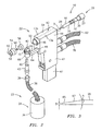
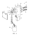
- microplasma spray coating apparatus 10 may comprise a microplasma gun 12 having a housing 13 containing an arc gas emitter 14, an anode 16, and a cathode 28.
- An electric arc 20 is generated between the anode 16 and cathode 28.
- a plasma stream 21 is formed when a quantity of arc gas is injected from the arc gas emitter 14 through the arc 20.
- a powdered material injector 22 dispenses a quantity of powdered material into the plasma stream which transports the powdered material to a workpiece 24.
- An arc gas source 15, a powder feeding system 23, a cooling fluid system 11 and a power source 17 are all connected to microplasma gun 12.
- the power source may operate in a power range necessary to perform the intended application of microplasma spray coating apparatus 10.
- the power source operates at a relatively low power range of about 0.5 kilowatts to about 4 kilowatts.
- the power source may comprise any power source capable of providing the aforementioned desired power ranges, and includes a power cord to engage various sized power outlets.
- a filter system 19 for collecting excess microplasma spray and/or powder material may be included in apparatus 10.
- Filter system 19 generally comprises a high efficiency particulate air filter having a hand held vacuum capable of removing excess powder from the air attached to a collection area, for example, a bag or container, where the excess powder is collected. Filter system 19 is preferably mounted to the mobile platform along with apparatus 10.
- the housing of microplasma gun 12 may comprise a grip portion 47, a forward wall 48, a first sidewall 49, a top wall 51, a backwall (not shown), and a second sidewall (not shown).
- the housing preferably comprises a first half 13a and a second half 13b; each half 13a, 13b includes a reciprocal male/female fastening mechanism such as, but not limited to, snaps, interlocking parts, depressed plunger and aperture, clips, clasps, combinations thereof, and the like, that are integrally formed therein.
- a nozzle shroud 46 positioned on a forward wall 48 of microplasma gun 12 may contain a nozzle insert 50 and a center aperture 52.
- the nozzle insert 50 may be threadingly attached to an end of nozzle shroud 46.
- a shield gas cap 54 may be positioned adjacent nozzle shroud 46,
- An insulator 56 may be positioned between a shield gas cap 54 and nozzle shroud 46 to electrically isolate shield gas cap 54 from nozzle shroud 46.
- Shield gas cap 54 may be pressed to fit over insulator 56 and onto nozzle shroud 46.
- Shield gas cap 54 includes a center aperture 60 to permit high velocity arc gas to pass through and into the electric arc.
- Shield gas cap 54 also includes a plurality of through apertures 58 for permitting shield gas to flow therethrough and shield the arc gas from ambient atmosphere.
- the shield gas flow rate may be about 2 to 4 liters per minute depending upon the intended application.
- the narrow spray pattern of microplasma stream 21 may also be controlled by the nozzle opening size.
- a cathode holder 26 includes a cathode 28 concentrically disposed within an insulating sleeve 18 and secured by an internal threaded mating juncture (not shown).
- Cathode holder 26 includes an insulating cap 27 for the holder's insertion and removal and a plurality of threads 30 for threadingly engaging insulating sleeve 18 and cathode 28 within microplasma gun 12.
- Insulating cap 27 and insulating sleeve 18 preferably comprise a nonconducting, insulating material such as phenolic materials, ceramic materials, polyetheretherketone materials, combinations thereof, and the like.
- cathode 28 When engaged, cathode 28 extends through center aperture 52 of nozzle shroud 46. Insulated sleeve 18 may also include an O-ring seal 32 to seal the leak path that is created at the interface between insulated sleeve 18 and microplasma gun 12.
- cathode 28 may comprise a body having a tip with a distal end. The tip may comprise a substantially flat upper surface formed at an angle of approximately 8 degrees to 30 degrees, preferably approximately 8 degrees to 20 degrees, and more preferably approximately 8 degrees to 10 degrees.
- the distal end of the tip comprises a height of about 0.008 inches to 0.030 inches (0.2 to 0.76 mm), preferably about 0.008 inches to 0.020 inches (0.2 to 0.5 mm), and most preferably about 0.008 inches to 0.010 inches (0.2 to 0.25 mm) or, in the alternative, a height measuring approximately 10% to 20% of the diameter of cathode 28.
- anode 16 comprises a metal or alloy having a melting point temperature higher than the intended operating temperature of the anode in microplasma gun 12.
- anode 16 comprises a commercially available pure sintered tungsten, or sintered tungsten blended with oxides exhibiting refactory characteristics, such as but not limited to thoria, lanthania, ceria, zirconia, and the like, and preferably blended with 2% thoria. These tungsten and oxide blends may be cryogenically treated in order to enhance and stabilize their performance in the microplasma spray gun apparatus.
- Conventional anodes are typically formed from a copper-tungsten alloy and provide a very limited service life of approximately 10 to 20 minutes in microplasma spray coating apparatus 10.
- Copper and other similar metals have melting point temperatures that are lower than the anode operating temperature. As a result, these metals can melt and cause an upper edge of the anode to become molten and initiate cavitation and erosion. In order to produce high quality coatings, the edge of the anode must remain relatively sharp. To achieve this, a commercially pure sintered tungsten material has been developed to produce a more robust anode. Test results using anodes made from sintered tungsten material has shown marked improvements in the erosion resistance over prior art anodes. Utilizing commercially pure tungsten in anode 16 has increased the service life of anode 16 such that anode 16 may be utilized in operation for approximately 10 hours to 20 hours.
- Electric arc 20 may be generated between anode 16 and cathode 28 of the microplasma gun 12.
- the arc gas may originate from an arc gas source 15 comprising a single gas or a mixture of gases, for example, a duplex gas, may originate from multiple gas sources interconnected with each other through a mixing apparatus and fed to the microplasma spray coating apparatus 10.
- the arc gas source 15 is connected to microplasma gun 12 via conduit having a length sufficient to permit slack so that the user of apparatus 10 may walk or climb, ascending or descending, with microplasma gun 12 a distance sufficient to perform the intended application without interrupting the flow of the arc gas to microplasma gun 12.
- arc gas source 15 comprising a single gas is particularly advantageous over utilizing a duplex gas mixture or multiple gas sources and a mixing apparatus due to lower costs and fewer materials and parts.
- a pre-mixed duplex gas mixture contained in a single arc gas source may also be utilized efficiently and cost effectively.
- the arc gas may comprise, but is not limited to, any inert gas and preferably comprises argon, and a representative duplex gas mixture may comprise argon and hydrogen, and preferably, about 98% argon gas and about 2% hydrogen gas.
- the arc gas may be admitted into the electric arc formed between anode 16 and cathode 28.
- the arc gas flow rate into microplasma spray coating apparatus 10 may be about 0.5 to 3 liters per minute.
- the electric arc ionizes the arc gas to create microplasma gas stream 21.
- the ionization process removes electrons from the arc gas, thus causing the arc gas to become temporarily unstable.
- the arc gas heats up to about 20,000°F to 30,000°F (11097°C to 16426°C) as it restabilizes.
- the microplasma gas stream then cools rapidly after passing through the electric arc.
- a powdered material injector 22 injects an amount of powdered material 34 into plasma gas stream 21.
- Powdered material 34 is heated and super-plasticized in the microplasma stream and is deposited on a workpiece where the deposited powdered material may cool and re-solidify to form the microplasma spray coating.
- Powdered material injector 22 may comprise a powder hopper 36. Powder hopper 36 holds powder material 34 prior to being injected into microplasma gas stream 21 by powder injector 22.
- Hopper 36 may be attached to microplasma gun 12 via a connector 38 formed on microplasma gun 12.
- Powdered material 34 may be channeled through a discharge orifice 40 and controlled by a valve 42 positioned therein.
- the powdered material 34 may be injected into microplasma gas stream 21 either through gravity feed or through a pressurized system (not known). In the alternative, powder material 34 may also be injected into microplasma stream 21 via a powder feeder hose from a standard powder feeder (not shown).
- Microplasma spray gun may be oriented between a positive 45° angle and a negative 45° angle relative to a normal axis of the workpiece, while still providing adequate material coating with a gravity feed system.
- a pressure feed system provides unlimited angles and/or orientation for microplasma gun 12.
- connector 38 or powdered feeder hose (not shown) preferably has a length sufficient to permit slack so that the user of apparatus 10 may walk or climb a distance sufficient to perform the intended application.
- the pressure feed systems contemplated for use herein preferably have the power capacity to uniformly force powdered material 34 through a powder feed hose positioned above or below powder hopper 36 and permit microplasma gun 12 to uniformly deliver powdered material 34 at unlimited angles and/or orientation.
- a shutoff control valve 42 also controls powder material 34 feed rate into plasma gas stream 21.
- Powdered material 34 may be transferred to the workpiece at a rate of about 1 to 30 grams per minute.
- Microplasma gun 12 may typically apply the microplasma spray coating from distances ranging from about 1.5 inches to 8 inches (38 to 203 mm) onto the workpiece, but may vary depending upon the coating application requirements.
- powdered material 34 may comprise any metallic, ceramic, carbide, cermet, plastic or other non-metallic coating material that can be typically plasma sprayed.
- powdered material may be include, but is not limited to, copper alloys, aluminum alloys, nickel alloys, e.g., nickel-aluminum alloy (95%/5%), in combination with a ceramic material such as a ceramic oxide including, but not limited to, yttria stabilized zirconia, aluminum oxide and the like.
- Microplasma spray gun 12, and microplasma spray coating apparatus 10 generates a relatively low noise level compared to conventional plasma spray coating apparatus.
- conventional plasma spray coating apparatus generate a noise level of about 120 decibels when taking into account the surrounding equipment and plasma spray coating apparatus itself.
- the microplasma spraying apparatus 10 may generate a noise level of about 40 decibels to 70 decibels during operation. More particularly, the microplasma spray coating apparatus 10 alone may generate a noise level of about 40 decibels to 55 decibels, and when surrounding equipment is included, the noise level may elevate to a range of about 55 decibels to 70 decibels.
- microplasma spray coating apparatus 10 of the present invention generates a noise level far lower than conventional plasma spray coating apparatus known today.
- current United States Government regulations require hearing protection when environmental noise reaches 85 decibels. As a result, microplasma spray coating apparatus 10 also meets Government regulated safety protocols.
- Coolant fluid such as water or the like, may be utilized to cool the microplasma gun 12.
- the cooling fluid may be delivered to the microplasma gun 12 via a cooling fluid hose 62.
- the cooling fluid traverses through internal passages (not shown) in the microplasma gun 12 and flows through an inlet passage 64, into an anode holder 66 and back through an outlet passage 68.
- the cooling fluid reduces the temperature of anode 16 during operation of the microplasma gun 12.
- the cooling flow rate may be approximately 0.1 to 1.0 gallons per minute.
- a second conduit 70 may be connected to the microplasma gun 12 in order to provide electrical power, arc gas, and chilled gas to the microplasma gun 12. Second conduit 70 preferably has a length sufficient to permit slack so that the user of apparatus 10 may walk or climb a distance with microplasma gun 12 sufficient to perform the intended application.
- FIG. 4 a block diagram generally illustrating the operation of microplasma spray coating apparatus 10 is illustrated.
- gas is emitted from nozzle insert 50.
- An electric potential is generated between anode 16 and cathode 28 of the microplasma spray gun 12 and is directed through the are gas, as described in block 82.
- Arc gas may be directed through the electric potential to create plasma stream 21.
- powder material 34 is injected into plasma stream 21.
- the microplasma stream heats the powder material 34 to a "super plasticized" condition such that the powder material 34 is malleable when it is applied to the workpiece.
- Superplasticized refers to the powdered material existing in a molten state, e.g., molten droplets, that freeze upon impact with the substrate surface and an entrained solid particulate state that melts upon impact with the substrate surface.
- powder material 34 is applied to an unmasked workpiece. Powder material 34 then cools and solidifies as a hard coating on the workpiece.
- the thickness of the microplasma spray coating may be dependent upon the intended application such as coating an OEM part or applying the coating for repair purposes.
- a workpiece may be spray coated with powder material 34 utilizing the microplasma spray coating apparatus described herein.
- Plasma gas stream 21 may be directed toward the workpiece being coated.
- Microplasma gun 12 may be operated at a relatively low power range of about 0.5 kilowatts to about 4 kilowatts.
- the lower power output of the microplasma gun 12 and microplasma spray coating apparatus 10 significantly reduces the heat flow into the workpiece over that of conventional plasma coating methods.
- maximum surface temperature of the workpiece achieved by the application of the microplasma spray coating process described herein may be about 200°F (93°C).
- microplasma spray coating apparatus 10 is capable of applying a microplasma spray coating to a thin wall area of the workpiece, without distortion resulting due to localized stress caused by high thermal gradients.
- microplasma spray gun 12 may apply powdered coating material in a localized area on a workpiece at a size of approximately 1/10 th to approximately 1/20 th , and preferably approximately 1/15 th , that of conventional plasma stream coating methods and apparatus.
- the size and diameter of the microplasma stream of microplasma spray coating apparatus 10 permits accurate surface coating even with a hand-held device as contemplated herein.
- the microplasma stream generated by microplasma spray coating apparatus 10 may comprise a width of about 0.5 millimeters to about 5 millimeters. Due to the size of the microplasma spray coating stream of the microplasma spray coating apparatus, the stream may be applied in narrow strips or in isolated areas on the workpiece which substantially eliminates the need for masking or otherwise covering the workpiece in areas where the coating is not desired.
Landscapes
- Engineering & Computer Science (AREA)
- Physics & Mathematics (AREA)
- Plasma & Fusion (AREA)
- Chemical & Material Sciences (AREA)
- Mechanical Engineering (AREA)
- Electromagnetism (AREA)
- Spectroscopy & Molecular Physics (AREA)
- Chemical Kinetics & Catalysis (AREA)
- Materials Engineering (AREA)
- Metallurgy (AREA)
- Organic Chemistry (AREA)
- Nozzles (AREA)
- Coating By Spraying Or Casting (AREA)
- Application Of Or Painting With Fluid Materials (AREA)
Claims (30)
- Tragbare, in der Hand zu haltende Mikroplasma-Sprühbeschichtungsvorrichtung (10), die Folgendes aufweist:eine Anode (16), eine Kathode (28) und einen Lichtbogengasemitter (14), diein einem Gehäuse (13) einer Mikroplasma-Sprühpistole (12) angeordnet sind;ein mit dem Gehäuse (13) verbundenes Pulverzuführsystem (23);ein mit dem Gehäuse (13) verbundenes Kühlsystem (11); undeine mit der Vorrichtung verbundene Energiequelle (17),wobei das Pulverzuführsystem (23), das Kühlsystem (11) und die Energiequelle (17) an einer mobilen Plattform lösbar angebracht sind.
- Tragbare, in der Hand zu haltende Mikroplasma-Vorrichtung nach Anspruch 1,
wobei die Anode (16) ein gesintertes Wolframmaterial aufweist. - Tragbare, in der Hand zu haltende Mikroplasma-Vorrichtung nach Anspruch 1 oder 2,
wobei die Kathode (28) in einer isolierenden Hülse (18) konzentrisch angeordnet ist, von der sich die Kathode (28) weg erstreckt und die durch eine Mehrzahl von Gewinden (30) und eine isolierende Kappe (27) in abgedichteter Weise mit dem Gehäuse (13) in Eingriff ist. - Tragbare, in der Hand zu haltende Mikroplasma-Vorrichtung nach Anspruch 3,
wobei die Kathode (28) einen Körper aufweist, der eine Spitze mit einem distalen Ende hat. - Tragbare, in der Hand zu haltende Mikroplasma-Vorrichtung nach Anspruch 4,
wobei die Spitze eine im Wesentlichen ebene obere Oberfläche aufweist, die in einem Winkel von ca. 8° bis 30° ausgebildet ist. - Tragbare, in der Hand zu haltende Mikroplasma-Vorrichtung nach Anspruch 4 oder 5,
wobei das distale Ende der Spitze eine Höhe von etwa 0,008 inch bis 0,030 inch (0,2 bis 0,76 mm) aufweist. - Tragbare, in der Hand zu haltende Mikroplasma-Vorrichtung nach Anspruch 4, 5 oder 6, wobei das distale Ende der Spitze eine Höhe von etwa 10% bis 20% des Durchmessers der Elektrode aufweist.
- Tragbare, in der Hand zu haltende Mikroplasma-Vorrichtung nach einem der vorausgehenden Ansprüche,
wobei die Anode (16) ein elektrisch leitfähiges Material aufweist. - Tragbare, in der Hand zu haltende. Mikroplasma-Vorrichtung nach Anspruch 8,
wobei das elektrisch leitfähige Material Wolfram, gemischt mit einem Oxid, aufweist, das aus der Gruppe bestehend aus Thoriumoxid, Lanthanoxid, Ceroxid und Zirconoxid ausgewählt ist. - Tragbare, in der Hand zu haltende Mikroplasma-Vorrichtung nach einem der vorausgehenden Ansprüche, wobei der Lichtbogengasemitter (14) ein inertes Lichtbogengas in einen von der Anode (16) und der Kathode (28) erzeugten elektrischen Lichtbogen (20) einleitet.
- Tragbare, in der Hand zu haltende Mikroplasma-Vorrichtung nach Anspruch 10,
weiterhin mit einem von dem inerten Lichtbogengas, welches durch den elektrischen Lichtbogen (20) tritt, erzeugten Plasmastrom (21). - Tragbare, in der Hand zu haltende Mikroplasma-Vorrichtung nach Anspruch 10 oder 11,
wobei es sich bei dem inerten Lichtbogengas um eine einzelne Gasquelle oder eine Duplex-Gasquelle handelt. - Tragbare, in der Hand zu haltende Mikroplasma-Vorrichtung nach Anspruch 12,
wobei es sich bei der einzelnen Gasquelle um Argon handelt. - Tragbare, in der Hand zu haltende Mikroplasma-Vorrichtung nach Anspruch 12,
wobei die Duplex-Gasquelle eine Mischung aus Argon und Wasserstoff umfasst. - Tragbare, in der Hand zu haltende Mikroplasma-Vorrichtung nach einem der vorausgehenden Ansprüche,
wobei das Pulverzuführsystem einen Pulverbehälter (36) aufweist, der mit dem Gehäuse (13) durch eine Leitung (38) zu einer Pulverinjektordüse verbunden ist, die sich durch eine in der Anode (16) ausgebildete Öffnung erstreckt. - Tragbare, in der Hand zu haltende Mikroplasma-Vorrichtung nach Anspruch 15,
wobei der Pulverbehälter (36) eine Menge am Pulvermaterial (34) enthält und dieses durch die Pulverinjektordüse in einen durch ein inertes Lichtbogengas, das durch einen von der Anode (16) und der Kathode (28) erzeugten elektrischen Lichtbogen tritt, erzeugten Plasmastrom (21) einbringt. - Tragbare, in der Hand zu haltende Mikroplasma-Vorrichtung nach Anspruch 15,
wobei der Pulverbehälter (36) etwa 1 bis 30 g Pulvermaterial pro Minute in die Pulverinjektordüse einbringt. - Tragbare, in der Hand zu haltende Mikroplasma-Vorrichtung nach Anspruch 15, 16 oder 17,
wobei die Leitung (38) eine ausreichende Länge aufweist, um einem Benutzer die Möglichkeit zu geben, sich über eine ausreichende Distanz zum Ausführen einer Anwendung zu bewegen. - Tragbare, in der Hand zu haltende Mikroplasma-Vorrichtung nach einem der vorausgehenden Ansprüche,
wobei das Kühlsystem (11) eine mit dem Gehäuse verbundene Kühlfluidleitung (62) aufweist, die durch eine Einlasspassage (64) in einen Anodenhalter (66) des Gehäuses (13) eintritt und durch eine Auslasspassage (68) austritt. - Tragbare, in der Hand zu haltende Mikroplasma-Vorrichtung nach Anspruch 19,
wobei die Kühlfluidleitung (62) ein Kühlfluid mit einer Strömungsrate von etwa 0,1 bis 1,0 Gallonen/min zuführt. - Tragbare, in der Hand zu haltende Mikroplasma-Vorrichtung nach Anspruch 19 oder 20,
wobei die Kühlfluidleitung (62) eine ausreichende Länge aufweist, um einem Benutzer die Möglichkeit zu geben, sich über eine ausreichende Distanz zum Ausführen einer Anwendung ohne Unterbrechung eines Stroms des Pulvermaterials zu bewegen. - Tragbare, in der Hand zu haltende Mikroplasma-Vorrichtung nach einem der vorausgehenden Ansprüche,
wobei die Energiequelle (17) eine Ausgangsleistung von etwa 0,5 kW bis etwa 4 kW erzeugt. - Tragbare, in der Hand zu haltende Mikroplasma-Vorrichtung nach einem der vorausgehenden Ansprüche,
wobei die Energiequelle (17) wiederaufladbar ist. - Tragbare, in der Hand zu haltende Mikroplasma-Vorrichtung nach einem der vorausgehenden Ansprüche,
wobei die Energiequelle (17) mit der Mikroplasma-Sprühpistole (12) durch eine Leitung mit einer ausreichenden Länge verbunden ist, damit ein Benutzer sich über eine ausreichende Distanz zum Ausführen einer Anwendung ohne Unterbrechung eines Stroms des Pulvermaterials bewegen kann. - Tragbare, in der Hand zu haltende Mikroplasma-Vorrichtung nach einem der vorausgehenden Ansprüche,
wobei die mobile Plattform ein Fahrzeug aufweist. - Tragbare, in der Hand zu haltende Mikroplasma-Vorrichtung nach einem der vorausgehenden Ansprüche,
weiterhin mit einer unter Druck stehenden Trägergasquelle, die mit dem Gehäuse (13) durch eine zweite Leitung verbunden ist. - Tragbare, in der Hand zu haltende Mikroplasma-Vorrichtung nach Anspruch 26,
wobei die zweite Leitung eine ausreichende Länge aufweist, damit sich ein Benutzer über eine ausreichende Distanz zum Ausführen einer Anwendung bewegen kann. - Tragbare, in der Hand zu haltende Mikroplasma-Vorrichtung nach einem der vorausgehenden Ansprüche,
wobei das Gehäuse (13) eine vordere Wand (48) mit einer daran angeordneten Düsenabdeckung (46), einen in einer Öffnung der Düsenabdeckung (46) konzentrisch angeordneten Düseneinsatz (50) sowie eine auf einem Isolator der Düsenabdeckung (46) angeordnete Abschirmgaskappe (54) aufweist. - Tragbare, in der Hand zu haltende Mikroplasma-Vorrichtung nach einem der vorausgehenden Ansprüche,
weiterhin mit einem tragbaren Filtersystem (19), das ein Feststoffluftfilter mit hoher Effizienz aufweist, das eine Unterdruckvorrichtung und einen Sammelbereich zum Aufnehmen einer Menge an überschüssigem Pulvermaterial und Mikroplasma-Sprühmaterial aufweist. - Tragbare, in der Hand zu haltende Mikroplasma-Vorrichtung, die an einer mobilen Plattform angebracht ist, aufweisend:eine Anode (16), eine Kathode (28) und einen Lichtbogengasemitter (14), die in einem Gehäuse (13) angeordnet sind;ein mit dem Gehäuse (13) verbundenes Pulverzuführsystem (23);ein mit dem Gehäuse (13) verbundenes Kühlsystem (11);eine mit der Vorrichtung verbundene Energiequelle (17), die zum Erzeugen einer Ausgangsleistung von etwa 0,5 kW bis etwa 4 kW in der Lage ist; undein Filtersystem (19) mit einem Feststoffluftfilter mit hoher Effizienz, wobei das Pulverzuführsystem (23), das Kühlsystem (11), die Energiequelle (17) und das Filtersystem (19) an einer mobilen Plattform angebracht sind.
Applications Claiming Priority (2)
| Application Number | Priority Date | Filing Date | Title |
|---|---|---|---|
| US11/190,135 US7115832B1 (en) | 2005-07-26 | 2005-07-26 | Microplasma spray coating apparatus |
| US11/253,868 US20070087129A1 (en) | 2005-10-19 | 2005-10-19 | Methods for repairing a workpiece |
Publications (2)
| Publication Number | Publication Date |
|---|---|
| EP1749583A1 EP1749583A1 (de) | 2007-02-07 |
| EP1749583B1 true EP1749583B1 (de) | 2008-01-09 |
Family
ID=37986863
Family Applications (1)
| Application Number | Title | Priority Date | Filing Date |
|---|---|---|---|
| EP05256728A Expired - Lifetime EP1749583B1 (de) | 2005-07-26 | 2005-10-31 | Vorrichtung zur Sprühbeschichtung von Mikroplasma |
Country Status (3)
| Country | Link |
|---|---|
| EP (1) | EP1749583B1 (de) |
| AT (1) | ATE383207T1 (de) |
| DE (1) | DE602005004277T2 (de) |
Families Citing this family (3)
| Publication number | Priority date | Publication date | Assignee | Title |
|---|---|---|---|---|
| US9950481B2 (en) | 2007-05-01 | 2018-04-24 | Exatec Llc | Edge healing and field repair of plasma coating |
| US10190442B2 (en) | 2016-03-22 | 2019-01-29 | General Electric Company | Gas turbine in situ inflatable bladders for on-wing repair |
| US10144096B2 (en) | 2016-03-22 | 2018-12-04 | General Electric Company | Gas turbine in situ inflatable bladders for on-wing repair |
Family Cites Families (7)
| Publication number | Priority date | Publication date | Assignee | Title |
|---|---|---|---|---|
| US4122327A (en) * | 1975-07-17 | 1978-10-24 | Metco Inc. | Automatic plasma flame spraying process and apparatus |
| US5723078A (en) * | 1996-05-24 | 1998-03-03 | General Electric Company | Method for repairing a thermal barrier coating |
| FR2827311B1 (fr) * | 2001-07-12 | 2003-09-19 | Snecma Moteurs | Procede de reparation locale de pieces revetues d'une barriere thermique |
| JP2003036996A (ja) * | 2001-07-23 | 2003-02-07 | Kikuchi Jun | 平行平板容量結合型微小プラズマ発生装置 |
| US7056416B2 (en) * | 2002-02-15 | 2006-06-06 | Matsushita Electric Industrial Co., Ltd. | Atmospheric pressure plasma processing method and apparatus |
| US7022615B2 (en) * | 2002-11-26 | 2006-04-04 | Matsushita Electric Industrial Co., Ltd. | Plasma processing method |
| JP2005194599A (ja) * | 2004-01-09 | 2005-07-21 | Mitsubishi Heavy Ind Ltd | プラズマ溶射装置および同装置における溶射粒子温度の検出方法 |
-
2005
- 2005-10-31 DE DE602005004277T patent/DE602005004277T2/de not_active Expired - Lifetime
- 2005-10-31 AT AT05256728T patent/ATE383207T1/de not_active IP Right Cessation
- 2005-10-31 EP EP05256728A patent/EP1749583B1/de not_active Expired - Lifetime
Also Published As
| Publication number | Publication date |
|---|---|
| ATE383207T1 (de) | 2008-01-15 |
| EP1749583A1 (de) | 2007-02-07 |
| DE602005004277T2 (de) | 2008-04-17 |
| DE602005004277D1 (de) | 2008-02-21 |
Similar Documents
| Publication | Publication Date | Title |
|---|---|---|
| US7115832B1 (en) | Microplasma spray coating apparatus | |
| US8507826B2 (en) | Microplasma spray apparatus and method for coating articles using same | |
| US5041713A (en) | Apparatus and method for applying plasma flame sprayed polymers | |
| US20090208662A1 (en) | Methods for Repairing a Workpiece | |
| US5044564A (en) | Electrostatic spray gun | |
| US20130098879A1 (en) | Method and Apparatus for Microplasma Spray Coating a Portion of a Turbine Vane in a Gas Turbine Engine | |
| US6863594B2 (en) | Method and device for cleaning high-voltage carrying installation component parts | |
| US8367967B2 (en) | Method and apparatus for repairing thermal barrier coatings | |
| GB1125806A (en) | Plasma guns | |
| MXPA04007706A (es) | Soplete para soldar por fusion laser, manual, alimentado por polvos. | |
| EP1652952B1 (de) | Verfahren zur Reparierung eines Werkstücks mittels Microplasmaspritzbeschichten. | |
| CN104364017A (zh) | 用于静电工具的气流开关 | |
| JP2005126750A (ja) | 溶射方法 | |
| EP2559784B1 (de) | Auftragsvorrichtung und Verfahren | |
| US7763823B2 (en) | Method and apparatus for microplasma spray coating a portion of a compressor blade in a gas turbine engine | |
| US20070023402A1 (en) | Methods for repairing workpieces using microplasma spray coating | |
| EP1652953B1 (de) | Verfahren zur Reparierung eines Werkstücks | |
| EP1749583A1 (de) | Vorrichtung zur Sprühbeschichtung von Mikroplasma | |
| JP2006131998A (ja) | マイクロプラズマ溶射装置 | |
| WO2006012165A2 (en) | Plasma jet generating apparatus and method of use thereof | |
| RU2672054C1 (ru) | Электродуговой плазмотрон для нанесения покрытий из тугоплавких дисперсных материалов | |
| EP1657322B1 (de) | Plasmasprühvorrichtung | |
| EP2878381A1 (de) | Düseneinsatz für thermische Sprühpistolenvorrichtung | |
| EP3126056B1 (de) | Elektrostatische sprühpistole mit externen ladepunkten | |
| RU2687905C1 (ru) | Электродуговой металлизатор "Дракон" |
Legal Events
| Date | Code | Title | Description |
|---|---|---|---|
| PUAI | Public reference made under article 153(3) epc to a published international application that has entered the european phase |
Free format text: ORIGINAL CODE: 0009012 |
|
| 17P | Request for examination filed |
Effective date: 20060629 |
|
| AK | Designated contracting states |
Kind code of ref document: A1 Designated state(s): AT BE BG CH CY CZ DE DK EE ES FI FR GB GR HU IE IS IT LI LT LU LV MC NL PL PT RO SE SI SK TR |
|
| AX | Request for extension of the european patent |
Extension state: AL BA HR MK YU |
|
| GRAP | Despatch of communication of intention to grant a patent |
Free format text: ORIGINAL CODE: EPIDOSNIGR1 |
|
| GRAS | Grant fee paid |
Free format text: ORIGINAL CODE: EPIDOSNIGR3 |
|
| AKX | Designation fees paid |
Designated state(s): AT BE BG CH CY CZ DE DK EE ES FI FR GB GR HU IE IS IT LI LT LU LV MC NL PL PT RO SE SI SK TR |
|
| GRAA | (expected) grant |
Free format text: ORIGINAL CODE: 0009210 |
|
| AK | Designated contracting states |
Kind code of ref document: B1 Designated state(s): AT BE BG CH CY CZ DE DK EE ES FI FR GB GR HU IE IS IT LI LT LU LV MC NL PL PT RO SE SI SK TR |
|
| REG | Reference to a national code |
Ref country code: GB Ref legal event code: FG4D |
|
| REG | Reference to a national code |
Ref country code: CH Ref legal event code: EP |
|
| REG | Reference to a national code |
Ref country code: IE Ref legal event code: FG4D |
|
| REF | Corresponds to: |
Ref document number: 602005004277 Country of ref document: DE Date of ref document: 20080221 Kind code of ref document: P |
|
| PG25 | Lapsed in a contracting state [announced via postgrant information from national office to epo] |
Ref country code: SI Free format text: LAPSE BECAUSE OF FAILURE TO SUBMIT A TRANSLATION OF THE DESCRIPTION OR TO PAY THE FEE WITHIN THE PRESCRIBED TIME-LIMIT Effective date: 20080109 Ref country code: NL Free format text: LAPSE BECAUSE OF FAILURE TO SUBMIT A TRANSLATION OF THE DESCRIPTION OR TO PAY THE FEE WITHIN THE PRESCRIBED TIME-LIMIT Effective date: 20080109 |
|
| NLV1 | Nl: lapsed or annulled due to failure to fulfill the requirements of art. 29p and 29m of the patents act | ||
| PG25 | Lapsed in a contracting state [announced via postgrant information from national office to epo] |
Ref country code: IS Free format text: LAPSE BECAUSE OF FAILURE TO SUBMIT A TRANSLATION OF THE DESCRIPTION OR TO PAY THE FEE WITHIN THE PRESCRIBED TIME-LIMIT Effective date: 20080509 Ref country code: ES Free format text: LAPSE BECAUSE OF FAILURE TO SUBMIT A TRANSLATION OF THE DESCRIPTION OR TO PAY THE FEE WITHIN THE PRESCRIBED TIME-LIMIT Effective date: 20080420 Ref country code: LI Free format text: LAPSE BECAUSE OF FAILURE TO SUBMIT A TRANSLATION OF THE DESCRIPTION OR TO PAY THE FEE WITHIN THE PRESCRIBED TIME-LIMIT Effective date: 20080109 Ref country code: LT Free format text: LAPSE BECAUSE OF FAILURE TO SUBMIT A TRANSLATION OF THE DESCRIPTION OR TO PAY THE FEE WITHIN THE PRESCRIBED TIME-LIMIT Effective date: 20080109 Ref country code: CH Free format text: LAPSE BECAUSE OF FAILURE TO SUBMIT A TRANSLATION OF THE DESCRIPTION OR TO PAY THE FEE WITHIN THE PRESCRIBED TIME-LIMIT Effective date: 20080109 Ref country code: FI Free format text: LAPSE BECAUSE OF FAILURE TO SUBMIT A TRANSLATION OF THE DESCRIPTION OR TO PAY THE FEE WITHIN THE PRESCRIBED TIME-LIMIT Effective date: 20080109 |
|
| REG | Reference to a national code |
Ref country code: CH Ref legal event code: PL |
|
| PG25 | Lapsed in a contracting state [announced via postgrant information from national office to epo] |
Ref country code: BG Free format text: LAPSE BECAUSE OF FAILURE TO SUBMIT A TRANSLATION OF THE DESCRIPTION OR TO PAY THE FEE WITHIN THE PRESCRIBED TIME-LIMIT Effective date: 20080409 Ref country code: AT Free format text: LAPSE BECAUSE OF FAILURE TO SUBMIT A TRANSLATION OF THE DESCRIPTION OR TO PAY THE FEE WITHIN THE PRESCRIBED TIME-LIMIT Effective date: 20080109 |
|
| PG25 | Lapsed in a contracting state [announced via postgrant information from national office to epo] |
Ref country code: LV Free format text: LAPSE BECAUSE OF FAILURE TO SUBMIT A TRANSLATION OF THE DESCRIPTION OR TO PAY THE FEE WITHIN THE PRESCRIBED TIME-LIMIT Effective date: 20080109 Ref country code: BE Free format text: LAPSE BECAUSE OF FAILURE TO SUBMIT A TRANSLATION OF THE DESCRIPTION OR TO PAY THE FEE WITHIN THE PRESCRIBED TIME-LIMIT Effective date: 20080109 Ref country code: PL Free format text: LAPSE BECAUSE OF FAILURE TO SUBMIT A TRANSLATION OF THE DESCRIPTION OR TO PAY THE FEE WITHIN THE PRESCRIBED TIME-LIMIT Effective date: 20080109 Ref country code: PT Free format text: LAPSE BECAUSE OF FAILURE TO SUBMIT A TRANSLATION OF THE DESCRIPTION OR TO PAY THE FEE WITHIN THE PRESCRIBED TIME-LIMIT Effective date: 20080609 |
|
| PLBI | Opposition filed |
Free format text: ORIGINAL CODE: 0009260 |
|
| EN | Fr: translation not filed | ||
| PG25 | Lapsed in a contracting state [announced via postgrant information from national office to epo] |
Ref country code: SE Free format text: LAPSE BECAUSE OF FAILURE TO SUBMIT A TRANSLATION OF THE DESCRIPTION OR TO PAY THE FEE WITHIN THE PRESCRIBED TIME-LIMIT Effective date: 20080409 Ref country code: DK Free format text: LAPSE BECAUSE OF FAILURE TO SUBMIT A TRANSLATION OF THE DESCRIPTION OR TO PAY THE FEE WITHIN THE PRESCRIBED TIME-LIMIT Effective date: 20080109 Ref country code: CZ Free format text: LAPSE BECAUSE OF FAILURE TO SUBMIT A TRANSLATION OF THE DESCRIPTION OR TO PAY THE FEE WITHIN THE PRESCRIBED TIME-LIMIT Effective date: 20080109 Ref country code: SK Free format text: LAPSE BECAUSE OF FAILURE TO SUBMIT A TRANSLATION OF THE DESCRIPTION OR TO PAY THE FEE WITHIN THE PRESCRIBED TIME-LIMIT Effective date: 20080109 |
|
| PLAX | Notice of opposition and request to file observation + time limit sent |
Free format text: ORIGINAL CODE: EPIDOSNOBS2 |
|
| 26 | Opposition filed |
Opponent name: SIEMENS AG Effective date: 20081007 |
|
| PG25 | Lapsed in a contracting state [announced via postgrant information from national office to epo] |
Ref country code: RO Free format text: LAPSE BECAUSE OF FAILURE TO SUBMIT A TRANSLATION OF THE DESCRIPTION OR TO PAY THE FEE WITHIN THE PRESCRIBED TIME-LIMIT Effective date: 20080109 |
|
| PLAF | Information modified related to communication of a notice of opposition and request to file observations + time limit |
Free format text: ORIGINAL CODE: EPIDOSCOBS2 |
|
| PG25 | Lapsed in a contracting state [announced via postgrant information from national office to epo] |
Ref country code: FR Free format text: LAPSE BECAUSE OF FAILURE TO SUBMIT A TRANSLATION OF THE DESCRIPTION OR TO PAY THE FEE WITHIN THE PRESCRIBED TIME-LIMIT Effective date: 20081031 Ref country code: EE Free format text: LAPSE BECAUSE OF FAILURE TO SUBMIT A TRANSLATION OF THE DESCRIPTION OR TO PAY THE FEE WITHIN THE PRESCRIBED TIME-LIMIT Effective date: 20080109 |
|
| PG25 | Lapsed in a contracting state [announced via postgrant information from national office to epo] |
Ref country code: MC Free format text: LAPSE BECAUSE OF NON-PAYMENT OF DUE FEES Effective date: 20081031 |
|
| PLAF | Information modified related to communication of a notice of opposition and request to file observations + time limit |
Free format text: ORIGINAL CODE: EPIDOSCOBS2 |
|
| PLBB | Reply of patent proprietor to notice(s) of opposition received |
Free format text: ORIGINAL CODE: EPIDOSNOBS3 |
|
| PG25 | Lapsed in a contracting state [announced via postgrant information from national office to epo] |
Ref country code: CY Free format text: LAPSE BECAUSE OF FAILURE TO SUBMIT A TRANSLATION OF THE DESCRIPTION OR TO PAY THE FEE WITHIN THE PRESCRIBED TIME-LIMIT Effective date: 20080109 |
|
| PG25 | Lapsed in a contracting state [announced via postgrant information from national office to epo] |
Ref country code: IT Free format text: LAPSE BECAUSE OF FAILURE TO SUBMIT A TRANSLATION OF THE DESCRIPTION OR TO PAY THE FEE WITHIN THE PRESCRIBED TIME-LIMIT Effective date: 20080109 |
|
| PG25 | Lapsed in a contracting state [announced via postgrant information from national office to epo] |
Ref country code: LU Free format text: LAPSE BECAUSE OF NON-PAYMENT OF DUE FEES Effective date: 20081031 Ref country code: HU Free format text: LAPSE BECAUSE OF FAILURE TO SUBMIT A TRANSLATION OF THE DESCRIPTION OR TO PAY THE FEE WITHIN THE PRESCRIBED TIME-LIMIT Effective date: 20080710 |
|
| PG25 | Lapsed in a contracting state [announced via postgrant information from national office to epo] |
Ref country code: TR Free format text: LAPSE BECAUSE OF FAILURE TO SUBMIT A TRANSLATION OF THE DESCRIPTION OR TO PAY THE FEE WITHIN THE PRESCRIBED TIME-LIMIT Effective date: 20080109 |
|
| PG25 | Lapsed in a contracting state [announced via postgrant information from national office to epo] |
Ref country code: GR Free format text: LAPSE BECAUSE OF FAILURE TO SUBMIT A TRANSLATION OF THE DESCRIPTION OR TO PAY THE FEE WITHIN THE PRESCRIBED TIME-LIMIT Effective date: 20080410 |
|
| PLCK | Communication despatched that opposition was rejected |
Free format text: ORIGINAL CODE: EPIDOSNREJ1 |
|
| PLBN | Opposition rejected |
Free format text: ORIGINAL CODE: 0009273 |
|
| STAA | Information on the status of an ep patent application or granted ep patent |
Free format text: STATUS: OPPOSITION REJECTED |
|
| 27O | Opposition rejected |
Effective date: 20131018 |
|
| REG | Reference to a national code |
Ref country code: DE Ref legal event code: R100 Ref document number: 602005004277 Country of ref document: DE Effective date: 20131018 |
|
| PGFP | Annual fee paid to national office [announced via postgrant information from national office to epo] |
Ref country code: IE Payment date: 20160922 Year of fee payment: 12 |
|
| REG | Reference to a national code |
Ref country code: DE Ref legal event code: R082 Ref document number: 602005004277 Country of ref document: DE Representative=s name: SCHMITT-NILSON SCHRAUD WAIBEL WOHLFROM PATENTA, DE |
|
| REG | Reference to a national code |
Ref country code: DE Ref legal event code: R082 Ref document number: 602005004277 Country of ref document: DE Representative=s name: SCHMITT-NILSON SCHRAUD WAIBEL WOHLFROM PATENTA, DE Ref country code: DE Ref legal event code: R081 Ref document number: 602005004277 Country of ref document: DE Owner name: UNITED TECHNOLOGIES CORP. (N.D.GES.D. STAATES , US Free format text: FORMER OWNER: UNITED TECHNOLOGIES CORPORATION, EAST HARTFORD, CONN., US |
|
| REG | Reference to a national code |
Ref country code: IE Ref legal event code: MM4A |
|
| PG25 | Lapsed in a contracting state [announced via postgrant information from national office to epo] |
Ref country code: IE Free format text: LAPSE BECAUSE OF NON-PAYMENT OF DUE FEES Effective date: 20171031 |
|
| PGFP | Annual fee paid to national office [announced via postgrant information from national office to epo] |
Ref country code: DE Payment date: 20190918 Year of fee payment: 15 |
|
| REG | Reference to a national code |
Ref country code: DE Ref legal event code: R119 Ref document number: 602005004277 Country of ref document: DE |
|
| PG25 | Lapsed in a contracting state [announced via postgrant information from national office to epo] |
Ref country code: DE Free format text: LAPSE BECAUSE OF NON-PAYMENT OF DUE FEES Effective date: 20210501 |
|
| PGFP | Annual fee paid to national office [announced via postgrant information from national office to epo] |
Ref country code: GB Payment date: 20240919 Year of fee payment: 20 |
|
| REG | Reference to a national code |
Ref country code: GB Ref legal event code: PE20 Expiry date: 20251030 |