EP1749689B1 - Bedienungsfeld für einen Traktor - Google Patents
Bedienungsfeld für einen Traktor Download PDFInfo
- Publication number
- EP1749689B1 EP1749689B1 EP06116872A EP06116872A EP1749689B1 EP 1749689 B1 EP1749689 B1 EP 1749689B1 EP 06116872 A EP06116872 A EP 06116872A EP 06116872 A EP06116872 A EP 06116872A EP 1749689 B1 EP1749689 B1 EP 1749689B1
- Authority
- EP
- European Patent Office
- Prior art keywords
- control panel
- control
- tractor
- buttons
- panel
- Prior art date
- Legal status (The legal status is an assumption and is not a legal conclusion. Google has not performed a legal analysis and makes no representation as to the accuracy of the status listed.)
- Ceased
Links
- 230000000007 visual effect Effects 0.000 claims description 8
- 239000011888 foil Substances 0.000 claims description 6
- 239000000463 material Substances 0.000 claims description 2
- 230000000994 depressogenic effect Effects 0.000 description 2
- 238000002372 labelling Methods 0.000 description 2
- 239000002184 metal Substances 0.000 description 2
- 241001236644 Lavinia Species 0.000 description 1
- 241001124569 Lycaenidae Species 0.000 description 1
- 238000013459 approach Methods 0.000 description 1
- 230000005540 biological transmission Effects 0.000 description 1
- 238000010586 diagram Methods 0.000 description 1
- 239000003381 stabilizer Substances 0.000 description 1
- 239000000725 suspension Substances 0.000 description 1
Images
Classifications
-
- B—PERFORMING OPERATIONS; TRANSPORTING
- B60—VEHICLES IN GENERAL
- B60K—ARRANGEMENT OR MOUNTING OF PROPULSION UNITS OR OF TRANSMISSIONS IN VEHICLES; ARRANGEMENT OR MOUNTING OF PLURAL DIVERSE PRIME-MOVERS IN VEHICLES; AUXILIARY DRIVES FOR VEHICLES; INSTRUMENTATION OR DASHBOARDS FOR VEHICLES; ARRANGEMENTS IN CONNECTION WITH COOLING, AIR INTAKE, GAS EXHAUST OR FUEL SUPPLY OF PROPULSION UNITS IN VEHICLES
- B60K35/00—Instruments specially adapted for vehicles; Arrangement of instruments in or on vehicles
- B60K35/10—Input arrangements, i.e. from user to vehicle, associated with vehicle functions or specially adapted therefor
-
- B—PERFORMING OPERATIONS; TRANSPORTING
- B60—VEHICLES IN GENERAL
- B60K—ARRANGEMENT OR MOUNTING OF PROPULSION UNITS OR OF TRANSMISSIONS IN VEHICLES; ARRANGEMENT OR MOUNTING OF PLURAL DIVERSE PRIME-MOVERS IN VEHICLES; AUXILIARY DRIVES FOR VEHICLES; INSTRUMENTATION OR DASHBOARDS FOR VEHICLES; ARRANGEMENTS IN CONNECTION WITH COOLING, AIR INTAKE, GAS EXHAUST OR FUEL SUPPLY OF PROPULSION UNITS IN VEHICLES
- B60K35/00—Instruments specially adapted for vehicles; Arrangement of instruments in or on vehicles
- B60K35/20—Output arrangements, i.e. from vehicle to user, associated with vehicle functions or specially adapted therefor
- B60K35/21—Output arrangements, i.e. from vehicle to user, associated with vehicle functions or specially adapted therefor using visual output, e.g. blinking lights or matrix displays
- B60K35/213—Virtual instruments
-
- B—PERFORMING OPERATIONS; TRANSPORTING
- B60—VEHICLES IN GENERAL
- B60K—ARRANGEMENT OR MOUNTING OF PROPULSION UNITS OR OF TRANSMISSIONS IN VEHICLES; ARRANGEMENT OR MOUNTING OF PLURAL DIVERSE PRIME-MOVERS IN VEHICLES; AUXILIARY DRIVES FOR VEHICLES; INSTRUMENTATION OR DASHBOARDS FOR VEHICLES; ARRANGEMENTS IN CONNECTION WITH COOLING, AIR INTAKE, GAS EXHAUST OR FUEL SUPPLY OF PROPULSION UNITS IN VEHICLES
- B60K2360/00—Indexing scheme associated with groups B60K35/00 or B60K37/00 relating to details of instruments or dashboards
- B60K2360/143—Touch sensitive instrument input devices
-
- B—PERFORMING OPERATIONS; TRANSPORTING
- B60—VEHICLES IN GENERAL
- B60Y—INDEXING SCHEME RELATING TO ASPECTS CROSS-CUTTING VEHICLE TECHNOLOGY
- B60Y2200/00—Type of vehicle
- B60Y2200/20—Off-Road Vehicles
- B60Y2200/22—Agricultural vehicles
- B60Y2200/221—Tractors
Definitions
- the present invention relates to a control panel for a tractor having a plurality of control devices mounted on a support plate.
- the invention finds particular application in agricultural machines, such as tractors and harvesters.
- control panel In a tractor, the control panel can prove confusing because of the large number of functions that are under the control of the operator. Switches are often labelled to indicate their function but an inexperienced operator may still have to spend time to search the control panel for a particular control. At best, this can be very distracting and on some occasions it may even prove dangerous. Furthermore, the labels may not be clearly legible under all lighting conditions, thereby adding to the confusion.
- GB 2.023.935 describes a switching device having a pictorial diagram, showing the top view of a car, printed on it. Arrows are located in the vicinity of the representation of the windows of the car. Upon pressing the downwards orientated arrow, the window corresponding to the pictorially represented window will open. When pressing the upward arrow, the corresponding window will close. Thus, electric switches are located on the switching device at a position relative to the markings which corresponds to the location on the car of the function controlled by the switches.
- US 6,935,434 on which the preamble of claim 1 is based, relates to a hitch control system having a display unit which includes a controller, a display and a rotary encoder.
- the rotary encoder is controlled by a rotary control knob. Further input is given to the controller by pressing a number of switches.
- the switches and the rotary control knob are mounted on the control panel itself. However, the control panel has no visual representation of the machine and the switches and rotary control knob are mounted at random on the control panel. When the driver needs to locate the switches, he will need to look for them and memorise where each switch is placed on the control panel.
- the present invention seeks therefore to provide a control panel that directs an experienced operator intuitively to the control device associated with any particular function.
- a control panel for a tractor having a plurality of control devices mounted on a support plate, the support plate additionally carries markings which visually represent the appearance of the tractor and each control device is located on the support panel at a position relative to the markings which corresponds to the location on the tractor of the function controlled by the device, wherein a rotary electronic draft control device is provided at the visual representation of a rear wheel of the tractor.
- An operator of a machine having a control panel of the invention will be presented with a visual image of the machine.
- Functions under control of the operator will each be associated with a part of the tractor and in the invention the controls for the functions are positioned in relation to the displayed image where the operator would intuitively expect to find them.
- controls for such items as a front hitch would be found by the front of the image of the tractor and the control for the rear power take off (PTO) shaft would be by the image of the rear of the vehicle.
- PTO power take off
- a rotary electronic draft control device may conveniently itself act as the visual representation of the rear wheel of the tractor.
- display devices may additionally be provided on the control panel to display the current status of functions controlled by the control devices, each display device being located at a position relative to the visual markings which corresponds to the location on the machine of the function of which the status is displayed by the device.
- control panel is constructed as a printed circuit board serving as a foil keyboard and having touch sensitive areas that act as switches and buttons.
- control panel further includes a front foil made of an electro luminescent (EL) material permitting the switches and buttons to be illuminated.
- EL electro luminescent
- each switch may have a unique EL backlighting feature identifying the function served by the switch and may also have an EL border line outlining the touch sensitive area of the switch.
- the panel may further be contoured or embossed to allow the position of switches and buttons to be determined by touch.
- a metal dome may also be included to allow each switch to provide tactile feedback that it has been depressed.
- the preferred embodiment of the invention provides a visually appealing and ergonomically designed control panel that avoids the need for labels and simplifies the tasks of identifying the function served by each control device and finding a control for any function.
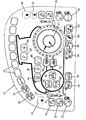
- the control panel 10 has a front EL foil which displays the illustrated image when illuminated.
- the image includes a representation of a tractor and rotary EDC (electronic draft control) potentiometer 12 is mounted within the rear tyre of the displayed image. Aside from this rotary potentiometer, and some display LED's nothing protrudes from the surface of the panel.
- EDC electronic draft control
- each button has an illuminated rim and a central icon.
- a metal dome may be used at each switch position to provide tactile feedback to the operator when a button has been sufficiently depressed to activate it.
- buttons presented and the functions that they serve will naturally vary from machine to machine. It is not therefore deemed necessary to provide a detailed description of each of the buttons illustrated in the drawing, especially as such controls are conventional and present in existing tractors, albeit in a different form. The buttons will therefore only be described to the extent that is necessary to demonstrate that their identification will be intuitive to even an inexperienced operator.
- the image of the tractor includes front and rear hitches 14 and 16. Adjacent the image of the front hitch 14 is a button 18 for raising the front hitch, a button 20 for lowering it and a button 22 for locking it in position.
- the button 22 is a master switch for disabling the switches 18 and 20 and its icon includes a small padlock. Also associated with the front hitch are three LED's 24, 26 and 28 and two arrows which indicate respectively that the front hitch is being raised, being lowered, or is locked in a fixed position.
- buttons 30 and 32 at the rear of the tractor are used to control the power take off shaft, the button 30 being an ON/OFF button and the button 32 for an AUTO mode of the take off shaft.
- a button 31 similar to the button 30 acts as an ON/OFF switch for the front PTO shaft.
- buttons 34 and 36 positioned near the image of the front wheel of the tractor are to select the four wheel drive (4WD) mode, the button 36 selecting 4WD at all times and the button 34 being for automatic selection of 4WD when the driving conditions require it.
- buttons 38, 40 and 42 control the front suspension, acting to raise, lower and suspend the front axle, respectively.
- Button 44 is for reversing the direction of the fan, this being required on occasions to clean the radiator.
- Button 46 is for manually reducing the engine speed and button 48 sets the rate at which the engine speed drops with increased load. Being associated with the operation of the engine, the buttons 44, 46 and 48 are naturally to be found in the image of the engine compartment.
- buttons 50 and 52 positioned in the image of the transmission are for the purpose of locking the differential or placing the differential in an automatic mode in which it will lock when the driving conditions require it.
- the button 54 at the rear of the tractor displaying the icon of a lifting cylinder is provided for locking the electro-hydraulic remotes.
- the image of the rear wheel contains a rotary potentiometer 12 and is associated with four buttons all of which are concerned with draft control.
- the plough can be raised and lower either to maintain a constant ploughing depth or a constant draft, i.e. a constant drag on the tractor.
- the potentiometer 12 is used in conjunction with the button 56 to set the permissible wheel slip, in conjunction with button 58 to proportion between draft control and depth control, in conjunction with the button 60 to set the maximum and minimum heights of the rear hitch and in conjunction with the button 62 to set the response speed of the EDC.
- the potentiometer 12 in the illustrated embodiment has two rotary controls to set maximum and minimum values of the relevant parameters but one could of course have separate buttons to allow a single potentiometer to set both minimum and maximum values.
- a button 64 is provided in the image of the cab to activate a parking lock and a further button 66 is to select the drive strategy (for example field or road mode).
- buttons 70 and 72 may be provided to control auxiliary features, these buttons being shown as operating a head turning sequence (HTS). These are effectively buttons which repeat a taught sequence of operations in particular the adjustment of speed and raising and lowering of a plough as the tractor approaches an edge of a field.
- HTS head turning sequence
- control panel is in many ways analogous to a computer keyboard and that the functions performed by the various buttons are dictated by software. Because of this, a single potentiometer can be used to set a variety of parameters if it is associated with buttons which select the function that it serves at any one time.
- buttons 74 after the HTS buttons 72, which are shown as being unmarked, are spare and intended to enable additional functions to be added to a control panel to customise it for any individual machine. It is for example possible to make provision for a film, which carries the symbols associated with the additional buttons, to be laid over the control panel.
- the electric circuits for sensing actuation of these additional buttons are already build into the control panel and apart from labelling the buttons, such as by the overlay film proposed above, the only other changes required can be implemented in software. Examples of functions to be controlled by these additional buttons are hydraulic stabilizers, a hydraulic lift rod and an electronically controlled front hitch. In this way, it is not only possible to customise a new control panel but a function can be added to an existing control panel, permitting it to be upgraded instead of it needing to be replaced.
Landscapes
- Engineering & Computer Science (AREA)
- Chemical & Material Sciences (AREA)
- Combustion & Propulsion (AREA)
- Transportation (AREA)
- Mechanical Engineering (AREA)
- Lifting Devices For Agricultural Implements (AREA)
- Soil Working Implements (AREA)
- Electroluminescent Light Sources (AREA)
- Agricultural Machines (AREA)
Claims (11)
- Bedienfeld (10) für einen Traktor mit einer Vielzahl von auf einer Trägerplatte befestigten Steuereinrichtungen, wobei die Trägerplatte zusätzlich Markierungen trägt, die visuell das Aussehen des Traktors darstellen, und jede Steuereinrichtung auf der Trägerplatte an einer Position bezüglich der Markierungen angeordnet ist, die der Lage der von der Einrichtung gesteuerten Funktion auf dem Traktor entspricht;
dadurch gekennzeichnet, dass eine rotierende elektronische Zugkraft-Steuereinrichtung (12) an der visuellen Darstellung eines Hinterrades des Traktors vorgesehen ist. - Bedienfeld nach Anspruch 1, bei dem eine Vielzahl von Auswahlknöpfen (56, 58, 60, 62) im Hinterrad des Traktors zugeordnet sind, um die Auswahl des Steuerparameters zu ermöglichen, der durch Drehen der rotierenden elektronischen Zugkraft-Steuereinrichtung (12) eingestellt wird.
- Bedienfeld nach einem der vorhergehenden Ansprüche, bei dem Anzeigeeinrichtungen (24, 26, 28) zusätzlich auf dem Bedienfeld vorgesehen sind, um den derzeitigen Status von Funktionen anzuzeigen, die von den Steuereinrichtungen gesteuert werden, wobei jede Anzeigeeinrichtung an einer Position bezüglich der visuellen Markierungen angeordnet ist, die der Position der Funktion, deren Status durch die Einrichtung angezeigt wird, auf dem Traktor entspricht.
- Bedienfeld nach einem der vorhergehenden Ansprüche, bei dem das Bedienfeld als eine gedruckte Leiterplatte aufgebaut ist, die als Folientastatur dient und druckempfindliche Bereiche aufweist, die als Schalter und Knöpfe wirken.
- Bedienfeld nach Anspruch 4, dass weiterhin eine vordere Folie einschließt, die aus einem elektrolumineszenten Material hergestellt ist und eine Beleuchtung der Schalter und Knöpfe ermöglicht.
- Bedienfeld nach einem der Ansprüche 4 oder 5, bei der jeder Schalter ein einzigartiges elekrolumineszentes Hintergrundbeleuchtungs-Merkmal aufweist, das die von dem Schalter erfüllte Funktion identifiziert.
- Bedienfeld nach einem der Ansprüche 4 bis 6, bei der eine Folie über dem Bedienfeld angeordnet ist und ein Bild zur Identifikation der Funktion trägt, die von einem im übrigen nicht markierten Schalter auf dem Bedienfeld erfüllt wird.
- Bedienfeld nach einem der Ansprüche 4 bis 7, bei der jeder Schalter weiterhin eine Umrandungslinie einschließt, die den druckempfindlichen Bereich des Schalters umreißt.
- Bedienfeld nach einem der vorhergehenden Ansprüche, bei dem das Bedienfeld konturiert oder geprägt ist, um die Erkennung der Position der Schalter und Knöpfe durch Berührung zu ermöglichen.
- Bedienfeld nach einem der vorhergehenden Ansprüche, bei dem die rotierende elektrische Steuereinrichtung ein Potentionmeter (12) ist, wobei das Potentionmeter (12) zumindest eine Drehsteuerung aufweist, um maximale und minimale Werte von zumindest einer Steuereinrichtung einzustellen.
- Bedienfeld nach einem der vorhergehenden Ansprüche, bei der die rotierende elektronische Zugkraft-Steuereinrichtung (12) als solche als visuelle Darstellung des Hinterrades des Traktors wirkt.
Applications Claiming Priority (1)
| Application Number | Priority Date | Filing Date | Title |
|---|---|---|---|
| GB0515101A GB2428770A (en) | 2005-07-25 | 2005-07-25 | Control panel with controls located on a visual representation of a machine |
Publications (2)
| Publication Number | Publication Date |
|---|---|
| EP1749689A1 EP1749689A1 (de) | 2007-02-07 |
| EP1749689B1 true EP1749689B1 (de) | 2010-06-16 |
Family
ID=34976409
Family Applications (1)
| Application Number | Title | Priority Date | Filing Date |
|---|---|---|---|
| EP06116872A Ceased EP1749689B1 (de) | 2005-07-25 | 2006-07-10 | Bedienungsfeld für einen Traktor |
Country Status (4)
| Country | Link |
|---|---|
| EP (1) | EP1749689B1 (de) |
| AT (1) | ATE471252T1 (de) |
| DE (1) | DE602006014908D1 (de) |
| GB (1) | GB2428770A (de) |
Families Citing this family (3)
| Publication number | Priority date | Publication date | Assignee | Title |
|---|---|---|---|---|
| KR101023655B1 (ko) * | 2008-10-08 | 2011-03-25 | 주식회사 메디슨 | 접촉을 통해 컨트롤 패널의 높이 조절이 가능한 초음파 진단기 |
| DE102009016919A1 (de) * | 2009-04-08 | 2010-10-21 | Jetter Ag | Steuerung einer Hubvorrichtung |
| FR3028628B1 (fr) | 2014-11-19 | 2017-06-09 | Manitou Bf | Dispositif et systeme de commande de fonctions de vehicule industriel ou tout terrain |
Family Cites Families (11)
| Publication number | Priority date | Publication date | Assignee | Title |
|---|---|---|---|---|
| GB2023935B (en) * | 1978-06-08 | 1982-08-25 | Nissan Motor | Electric switch |
| JPS587556Y2 (ja) * | 1978-11-08 | 1983-02-09 | 日産自動車株式会社 | 絵表示スイツチ |
| FR2580240B1 (fr) * | 1985-04-10 | 1987-07-10 | Citroen Maxime | Dispositif de regroupement constituant un clavier de contacteurs de commande d'equipements installes dans un vehicule automobile |
| DE3933562C2 (de) * | 1989-10-07 | 1994-02-17 | Daimler Benz Ag | Steuereinrichtung zur Verstellung von Kraftfahrzeugsitzen |
| GB2254640A (en) * | 1991-04-11 | 1992-10-14 | Meco Electronics Ltd | A control system for controlling a collection of mine roof supports |
| FR2727821A1 (fr) * | 1994-12-13 | 1996-06-14 | Lucas Sa G | Systeme de commande d'une machine munie de plusieurs organes moteurs hydrauliques, attelee a un tracteur agricole |
| GB9610124D0 (en) * | 1996-05-15 | 1996-07-24 | Massey Ferguson Sa | Control of a semi-mounted plough |
| US6275231B1 (en) * | 1997-08-01 | 2001-08-14 | American Calcar Inc. | Centralized control and management system for automobiles |
| DE10132323A1 (de) * | 2001-07-06 | 2003-01-16 | Deutsche Lufthansa | Bedienvorrichtung für einen Passagiersitz |
| DE10260305A1 (de) * | 2002-12-20 | 2004-07-15 | Siemens Ag | HMI Einrichtung mit einem optischem Touch Screen |
| US6935434B1 (en) | 2004-03-12 | 2005-08-30 | Deere & Company | Hitch control system with spring centered control lever |
-
2005
- 2005-07-25 GB GB0515101A patent/GB2428770A/en not_active Withdrawn
-
2006
- 2006-07-10 EP EP06116872A patent/EP1749689B1/de not_active Ceased
- 2006-07-10 AT AT06116872T patent/ATE471252T1/de not_active IP Right Cessation
- 2006-07-10 DE DE602006014908T patent/DE602006014908D1/de active Active
Also Published As
| Publication number | Publication date |
|---|---|
| GB2428770A (en) | 2007-02-07 |
| DE602006014908D1 (de) | 2010-07-29 |
| EP1749689A1 (de) | 2007-02-07 |
| ATE471252T1 (de) | 2010-07-15 |
| GB0515101D0 (en) | 2005-08-31 |
Similar Documents
| Publication | Publication Date | Title |
|---|---|---|
| US10606303B2 (en) | Control lever for a vehicle | |
| JP6698281B2 (ja) | 作業車両 | |
| US5821935A (en) | Graphical user interface with electronic feature access | |
| KR102010162B1 (ko) | 작업 차량 | |
| JP6247173B2 (ja) | 対地作業装置のための昇降制御装置 | |
| AU2014226472A1 (en) | System and method for controlling features | |
| US20080252600A1 (en) | Adaptable control device | |
| EP2990252B1 (de) | Geschwindigkeit-datenanzeigesystem für ein arbeitsfahrzeug | |
| CN108327650B (zh) | 作业车 | |
| US10795463B2 (en) | Machine control using a touchpad | |
| EP4122738A1 (de) | Konfigurierbare benutzerschnittstelle | |
| EP2518009A1 (de) | Flurförderzeug | |
| FI3511472T3 (fi) | Rakennuskone, erityisesti maansiirtokone, jossa on ohjauspaneeli | |
| KR20110100233A (ko) | 자동차의 작동 시스템 | |
| EP1749689A1 (de) | Bedienungsfeld für eine komplexe Maschine | |
| US11052760B2 (en) | Agricultural vehicle | |
| JP6403056B2 (ja) | 作業車両 | |
| JP3771080B2 (ja) | トラクタ | |
| JP7826183B2 (ja) | 作業車両の支援装置、及び作業車両 | |
| JP3979916B2 (ja) | 農作業機 | |
| RU2781962C2 (ru) | Строительная машина, в частности землеройно-транспортная машина с пультом обслуживания | |
| KR102394965B1 (ko) | 작업 차량 | |
| JP3557906B2 (ja) | 農業機械の液晶表示装置 | |
| JP2020022502A (ja) | 対地作業装置のための昇降制御装置 | |
| EP4137362A1 (de) | Flurförderzeug |
Legal Events
| Date | Code | Title | Description |
|---|---|---|---|
| PUAI | Public reference made under article 153(3) epc to a published international application that has entered the european phase |
Free format text: ORIGINAL CODE: 0009012 |
|
| AK | Designated contracting states |
Kind code of ref document: A1 Designated state(s): AT BE BG CH CY CZ DE DK EE ES FI FR GB GR HU IE IS IT LI LT LU LV MC NL PL PT RO SE SI SK TR |
|
| AX | Request for extension of the european patent |
Extension state: AL BA HR MK YU |
|
| 17P | Request for examination filed |
Effective date: 20070807 |
|
| 17Q | First examination report despatched |
Effective date: 20070905 |
|
| AKX | Designation fees paid |
Designated state(s): AT BE BG CH CY CZ DE DK EE ES FI FR GB GR HU IE IS IT LI LT LU LV MC NL PL PT RO SE SI SK TR |
|
| RTI1 | Title (correction) |
Free format text: CONTROL PANEL FOR A TRACTOR |
|
| GRAP | Despatch of communication of intention to grant a patent |
Free format text: ORIGINAL CODE: EPIDOSNIGR1 |
|
| GRAS | Grant fee paid |
Free format text: ORIGINAL CODE: EPIDOSNIGR3 |
|
| GRAA | (expected) grant |
Free format text: ORIGINAL CODE: 0009210 |
|
| AK | Designated contracting states |
Kind code of ref document: B1 Designated state(s): AT BE BG CH CY CZ DE DK EE ES FI FR GB GR HU IE IS IT LI LT LU LV MC NL PL PT RO SE SI SK TR |
|
| REG | Reference to a national code |
Ref country code: CH Ref legal event code: EP |
|
| REG | Reference to a national code |
Ref country code: IE Ref legal event code: FG4D |
|
| REF | Corresponds to: |
Ref document number: 602006014908 Country of ref document: DE Date of ref document: 20100729 Kind code of ref document: P |
|
| REG | Reference to a national code |
Ref country code: NL Ref legal event code: VDEP Effective date: 20100616 |
|
| PG25 | Lapsed in a contracting state [announced via postgrant information from national office to epo] |
Ref country code: SE Free format text: LAPSE BECAUSE OF FAILURE TO SUBMIT A TRANSLATION OF THE DESCRIPTION OR TO PAY THE FEE WITHIN THE PRESCRIBED TIME-LIMIT Effective date: 20100616 Ref country code: LT Free format text: LAPSE BECAUSE OF FAILURE TO SUBMIT A TRANSLATION OF THE DESCRIPTION OR TO PAY THE FEE WITHIN THE PRESCRIBED TIME-LIMIT Effective date: 20100616 |
|
| LTIE | Lt: invalidation of european patent or patent extension |
Effective date: 20100616 |
|
| PG25 | Lapsed in a contracting state [announced via postgrant information from national office to epo] |
Ref country code: SI Free format text: LAPSE BECAUSE OF FAILURE TO SUBMIT A TRANSLATION OF THE DESCRIPTION OR TO PAY THE FEE WITHIN THE PRESCRIBED TIME-LIMIT Effective date: 20100616 Ref country code: LV Free format text: LAPSE BECAUSE OF FAILURE TO SUBMIT A TRANSLATION OF THE DESCRIPTION OR TO PAY THE FEE WITHIN THE PRESCRIBED TIME-LIMIT Effective date: 20100616 Ref country code: AT Free format text: LAPSE BECAUSE OF FAILURE TO SUBMIT A TRANSLATION OF THE DESCRIPTION OR TO PAY THE FEE WITHIN THE PRESCRIBED TIME-LIMIT Effective date: 20100616 Ref country code: FI Free format text: LAPSE BECAUSE OF FAILURE TO SUBMIT A TRANSLATION OF THE DESCRIPTION OR TO PAY THE FEE WITHIN THE PRESCRIBED TIME-LIMIT Effective date: 20100616 |
|
| PG25 | Lapsed in a contracting state [announced via postgrant information from national office to epo] |
Ref country code: GR Free format text: LAPSE BECAUSE OF FAILURE TO SUBMIT A TRANSLATION OF THE DESCRIPTION OR TO PAY THE FEE WITHIN THE PRESCRIBED TIME-LIMIT Effective date: 20100917 Ref country code: PL Free format text: LAPSE BECAUSE OF FAILURE TO SUBMIT A TRANSLATION OF THE DESCRIPTION OR TO PAY THE FEE WITHIN THE PRESCRIBED TIME-LIMIT Effective date: 20100616 Ref country code: CY Free format text: LAPSE BECAUSE OF FAILURE TO SUBMIT A TRANSLATION OF THE DESCRIPTION OR TO PAY THE FEE WITHIN THE PRESCRIBED TIME-LIMIT Effective date: 20100616 |
|
| PG25 | Lapsed in a contracting state [announced via postgrant information from national office to epo] |
Ref country code: NL Free format text: LAPSE BECAUSE OF FAILURE TO SUBMIT A TRANSLATION OF THE DESCRIPTION OR TO PAY THE FEE WITHIN THE PRESCRIBED TIME-LIMIT Effective date: 20100616 Ref country code: EE Free format text: LAPSE BECAUSE OF FAILURE TO SUBMIT A TRANSLATION OF THE DESCRIPTION OR TO PAY THE FEE WITHIN THE PRESCRIBED TIME-LIMIT Effective date: 20100616 |
|
| PG25 | Lapsed in a contracting state [announced via postgrant information from national office to epo] |
Ref country code: RO Free format text: LAPSE BECAUSE OF FAILURE TO SUBMIT A TRANSLATION OF THE DESCRIPTION OR TO PAY THE FEE WITHIN THE PRESCRIBED TIME-LIMIT Effective date: 20100616 Ref country code: BE Free format text: LAPSE BECAUSE OF FAILURE TO SUBMIT A TRANSLATION OF THE DESCRIPTION OR TO PAY THE FEE WITHIN THE PRESCRIBED TIME-LIMIT Effective date: 20100616 Ref country code: MC Free format text: LAPSE BECAUSE OF NON-PAYMENT OF DUE FEES Effective date: 20100731 Ref country code: IS Free format text: LAPSE BECAUSE OF FAILURE TO SUBMIT A TRANSLATION OF THE DESCRIPTION OR TO PAY THE FEE WITHIN THE PRESCRIBED TIME-LIMIT Effective date: 20101016 Ref country code: CZ Free format text: LAPSE BECAUSE OF FAILURE TO SUBMIT A TRANSLATION OF THE DESCRIPTION OR TO PAY THE FEE WITHIN THE PRESCRIBED TIME-LIMIT Effective date: 20100616 Ref country code: PT Free format text: LAPSE BECAUSE OF FAILURE TO SUBMIT A TRANSLATION OF THE DESCRIPTION OR TO PAY THE FEE WITHIN THE PRESCRIBED TIME-LIMIT Effective date: 20101018 Ref country code: SK Free format text: LAPSE BECAUSE OF FAILURE TO SUBMIT A TRANSLATION OF THE DESCRIPTION OR TO PAY THE FEE WITHIN THE PRESCRIBED TIME-LIMIT Effective date: 20100616 |
|
| REG | Reference to a national code |
Ref country code: CH Ref legal event code: PL |
|
| PLBE | No opposition filed within time limit |
Free format text: ORIGINAL CODE: 0009261 |
|
| STAA | Information on the status of an ep patent application or granted ep patent |
Free format text: STATUS: NO OPPOSITION FILED WITHIN TIME LIMIT |
|
| PG25 | Lapsed in a contracting state [announced via postgrant information from national office to epo] |
Ref country code: DK Free format text: LAPSE BECAUSE OF FAILURE TO SUBMIT A TRANSLATION OF THE DESCRIPTION OR TO PAY THE FEE WITHIN THE PRESCRIBED TIME-LIMIT Effective date: 20100616 Ref country code: LI Free format text: LAPSE BECAUSE OF NON-PAYMENT OF DUE FEES Effective date: 20100731 Ref country code: CH Free format text: LAPSE BECAUSE OF NON-PAYMENT OF DUE FEES Effective date: 20100731 |
|
| 26N | No opposition filed |
Effective date: 20110317 |
|
| PG25 | Lapsed in a contracting state [announced via postgrant information from national office to epo] |
Ref country code: IT Free format text: LAPSE BECAUSE OF NON-PAYMENT OF DUE FEES Effective date: 20100710 |
|
| REG | Reference to a national code |
Ref country code: DE Ref legal event code: R097 Ref document number: 602006014908 Country of ref document: DE Effective date: 20110316 |
|
| PG25 | Lapsed in a contracting state [announced via postgrant information from national office to epo] |
Ref country code: IE Free format text: LAPSE BECAUSE OF NON-PAYMENT OF DUE FEES Effective date: 20100710 |
|
| PGRI | Patent reinstated in contracting state [announced from national office to epo] |
Ref country code: IT Effective date: 20110616 |
|
| PG25 | Lapsed in a contracting state [announced via postgrant information from national office to epo] |
Ref country code: BG Free format text: LAPSE BECAUSE OF FAILURE TO SUBMIT A TRANSLATION OF THE DESCRIPTION OR TO PAY THE FEE WITHIN THE PRESCRIBED TIME-LIMIT Effective date: 20100616 Ref country code: LU Free format text: LAPSE BECAUSE OF NON-PAYMENT OF DUE FEES Effective date: 20100710 Ref country code: HU Free format text: LAPSE BECAUSE OF FAILURE TO SUBMIT A TRANSLATION OF THE DESCRIPTION OR TO PAY THE FEE WITHIN THE PRESCRIBED TIME-LIMIT Effective date: 20101217 |
|
| PG25 | Lapsed in a contracting state [announced via postgrant information from national office to epo] |
Ref country code: TR Free format text: LAPSE BECAUSE OF FAILURE TO SUBMIT A TRANSLATION OF THE DESCRIPTION OR TO PAY THE FEE WITHIN THE PRESCRIBED TIME-LIMIT Effective date: 20100616 |
|
| PG25 | Lapsed in a contracting state [announced via postgrant information from national office to epo] |
Ref country code: BG Free format text: LAPSE BECAUSE OF FAILURE TO SUBMIT A TRANSLATION OF THE DESCRIPTION OR TO PAY THE FEE WITHIN THE PRESCRIBED TIME-LIMIT Effective date: 20100916 |
|
| PG25 | Lapsed in a contracting state [announced via postgrant information from national office to epo] |
Ref country code: ES Free format text: LAPSE BECAUSE OF FAILURE TO SUBMIT A TRANSLATION OF THE DESCRIPTION OR TO PAY THE FEE WITHIN THE PRESCRIBED TIME-LIMIT Effective date: 20100927 |
|
| REG | Reference to a national code |
Ref country code: DE Ref legal event code: R082 Ref document number: 602006014908 Country of ref document: DE Representative=s name: PATENTANWAELTE WALLACH, KOCH & PARTNER, DE |
|
| REG | Reference to a national code |
Ref country code: DE Ref legal event code: R082 Ref document number: 602006014908 Country of ref document: DE Representative=s name: PATENTANWAELTE WALLACH, KOCH & PARTNER, DE Effective date: 20140422 Ref country code: DE Ref legal event code: R081 Ref document number: 602006014908 Country of ref document: DE Owner name: CNH INDUSTRIAL OESTERREICH GMBH, AT Free format text: FORMER OWNER: CNH OESTERREICH GMBH, ST. VALENTIN, AT Effective date: 20140422 Ref country code: DE Ref legal event code: R082 Ref document number: 602006014908 Country of ref document: DE Representative=s name: PATENTANWAELTE WALLACH, KOCH, DR. HAIBACH, FEL, DE Effective date: 20140422 |
|
| REG | Reference to a national code |
Ref country code: FR Ref legal event code: PLFP Year of fee payment: 11 |
|
| REG | Reference to a national code |
Ref country code: FR Ref legal event code: PLFP Year of fee payment: 12 |
|
| REG | Reference to a national code |
Ref country code: FR Ref legal event code: PLFP Year of fee payment: 13 |
|
| PGFP | Annual fee paid to national office [announced via postgrant information from national office to epo] |
Ref country code: IT Payment date: 20190711 Year of fee payment: 14 |
|
| PGFP | Annual fee paid to national office [announced via postgrant information from national office to epo] |
Ref country code: GB Payment date: 20190724 Year of fee payment: 14 |
|
| REG | Reference to a national code |
Ref country code: DE Ref legal event code: R084 Ref document number: 602006014908 Country of ref document: DE |
|
| GBPC | Gb: european patent ceased through non-payment of renewal fee |
Effective date: 20200710 |
|
| PG25 | Lapsed in a contracting state [announced via postgrant information from national office to epo] |
Ref country code: GB Free format text: LAPSE BECAUSE OF NON-PAYMENT OF DUE FEES Effective date: 20200710 |
|
| REG | Reference to a national code |
Ref country code: DE Ref legal event code: R082 Ref document number: 602006014908 Country of ref document: DE Representative=s name: MEISSNER BOLTE PATENTANWAELTE RECHTSANWAELTE P, DE |
|
| PG25 | Lapsed in a contracting state [announced via postgrant information from national office to epo] |
Ref country code: IT Free format text: LAPSE BECAUSE OF NON-PAYMENT OF DUE FEES Effective date: 20200710 |
|
| REG | Reference to a national code |
Ref country code: DE Ref legal event code: R079 Ref document number: 602006014908 Country of ref document: DE Free format text: PREVIOUS MAIN CLASS: B60K0037060000 Ipc: B60K0035100000 |
|
| PGFP | Annual fee paid to national office [announced via postgrant information from national office to epo] |
Ref country code: FR Payment date: 20230721 Year of fee payment: 18 Ref country code: DE Payment date: 20230724 Year of fee payment: 18 |
|
| REG | Reference to a national code |
Ref country code: DE Ref legal event code: R119 Ref document number: 602006014908 Country of ref document: DE |
|
| PG25 | Lapsed in a contracting state [announced via postgrant information from national office to epo] |
Ref country code: DE Free format text: LAPSE BECAUSE OF NON-PAYMENT OF DUE FEES Effective date: 20250201 |
|
| PG25 | Lapsed in a contracting state [announced via postgrant information from national office to epo] |
Ref country code: FR Free format text: LAPSE BECAUSE OF NON-PAYMENT OF DUE FEES Effective date: 20240731 |