EP1749727A1 - Schiebkarre, insbesondere für Strand- oder Freibadzubehör - Google Patents
Schiebkarre, insbesondere für Strand- oder Freibadzubehör Download PDFInfo
- Publication number
- EP1749727A1 EP1749727A1 EP06354023A EP06354023A EP1749727A1 EP 1749727 A1 EP1749727 A1 EP 1749727A1 EP 06354023 A EP06354023 A EP 06354023A EP 06354023 A EP06354023 A EP 06354023A EP 1749727 A1 EP1749727 A1 EP 1749727A1
- Authority
- EP
- European Patent Office
- Prior art keywords
- carriage
- transport
- rear surface
- trolley according
- trolley
- Prior art date
- Legal status (The legal status is an assumption and is not a legal conclusion. Google has not performed a legal analysis and makes no representation as to the accuracy of the status listed.)
- Withdrawn
Links
- 229910052751 metal Inorganic materials 0.000 claims description 17
- 239000002184 metal Substances 0.000 claims description 17
- 239000000463 material Substances 0.000 claims description 6
- 230000006641 stabilisation Effects 0.000 claims description 5
- 238000011105 stabilization Methods 0.000 claims description 5
- 230000000087 stabilizing effect Effects 0.000 claims description 4
- 239000004576 sand Substances 0.000 claims description 3
- 239000007787 solid Substances 0.000 claims description 2
- XLYOFNOQVPJJNP-UHFFFAOYSA-N water Substances O XLYOFNOQVPJJNP-UHFFFAOYSA-N 0.000 claims description 2
- 238000003860 storage Methods 0.000 abstract description 25
- 239000011521 glass Substances 0.000 abstract description 8
- 230000002787 reinforcement Effects 0.000 description 6
- 238000003287 bathing Methods 0.000 description 3
- 229920003023 plastic Polymers 0.000 description 3
- 230000003014 reinforcing effect Effects 0.000 description 3
- 239000002689 soil Substances 0.000 description 3
- 238000006073 displacement reaction Methods 0.000 description 2
- 206010016322 Feeling abnormal Diseases 0.000 description 1
- 230000001154 acute effect Effects 0.000 description 1
- 229910052782 aluminium Inorganic materials 0.000 description 1
- XAGFODPZIPBFFR-UHFFFAOYSA-N aluminium Chemical compound [Al] XAGFODPZIPBFFR-UHFFFAOYSA-N 0.000 description 1
- 239000000470 constituent Substances 0.000 description 1
- 230000000694 effects Effects 0.000 description 1
- 239000004744 fabric Substances 0.000 description 1
- 238000011065 in-situ storage Methods 0.000 description 1
- 238000003780 insertion Methods 0.000 description 1
- 230000037431 insertion Effects 0.000 description 1
- 238000012423 maintenance Methods 0.000 description 1
- 238000005096 rolling process Methods 0.000 description 1
- 230000009182 swimming Effects 0.000 description 1
- 125000000391 vinyl group Chemical group [H]C([*])=C([H])[H] 0.000 description 1
- 229920002554 vinyl polymer Polymers 0.000 description 1
- 230000036642 wellbeing Effects 0.000 description 1
Images




Classifications
-
- B—PERFORMING OPERATIONS; TRANSPORTING
- B62—LAND VEHICLES FOR TRAVELLING OTHERWISE THAN ON RAILS
- B62B—HAND-PROPELLED VEHICLES, e.g. HAND CARTS OR PERAMBULATORS; SLEDGES
- B62B1/00—Hand carts having only one axis carrying one or more transport wheels; Equipment therefor
- B62B1/10—Hand carts having only one axis carrying one or more transport wheels; Equipment therefor in which the load is intended to be transferred totally to the wheels
- B62B1/12—Hand carts having only one axis carrying one or more transport wheels; Equipment therefor in which the load is intended to be transferred totally to the wheels involving parts being adjustable, collapsible, attachable, detachable, or convertible
-
- B—PERFORMING OPERATIONS; TRANSPORTING
- B62—LAND VEHICLES FOR TRAVELLING OTHERWISE THAN ON RAILS
- B62B—HAND-PROPELLED VEHICLES, e.g. HAND CARTS OR PERAMBULATORS; SLEDGES
- B62B1/00—Hand carts having only one axis carrying one or more transport wheels; Equipment therefor
- B62B1/26—Hand carts having only one axis carrying one or more transport wheels; Equipment therefor characterised by supports specially adapted to objects of definite shape
-
- B—PERFORMING OPERATIONS; TRANSPORTING
- B62—LAND VEHICLES FOR TRAVELLING OTHERWISE THAN ON RAILS
- B62B—HAND-PROPELLED VEHICLES, e.g. HAND CARTS OR PERAMBULATORS; SLEDGES
- B62B2202/00—Indexing codes relating to type or characteristics of transported articles
- B62B2202/52—Beach or picnic trolleys
Definitions
- the document US 6,113,129 describes in particular a wheeled transport trolley, for beach accessories, comprising a pair of wheels and a gripping handle, defining a rear surface rectified carriage, during movement of the carriage.
- the carriage also has a support surface perpendicular to the rear surface and intended to receive, for example, a cooler, which is held by arms of adjustable length.
- the carriage comprises a first blind hole for positioning a parasol in the transport position, in which the umbrella is closed, and a second opening opening adjacent, in which the umbrella is inserted in the use position, for planting. the parasol in the ground.
- the invention aims to overcome the aforementioned drawbacks and is intended to provide a transport carriage, especially for beach accessories, which is easy to handle, easy to move and allows to use effectively a sunshade, which whatever the location of the transport trolley.
- this object is achieved by a transport carriage according to the appended claims and, more particularly, by the fact that, since the rear surface of the carriage is arranged substantially parallel to the ground in said position of use, the second means are arranged to position the sunshade substantially perpendicular to the rear surface the carriage in the use position and the carriage has stabilizing means in the use position.
- Another object of the invention relates to a support element that can serve as a backrest or headrest according to its configuration.
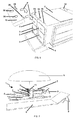
- the transport trolley 1 comprises a cooler 2 and storage drawers 3 (FIG. 6), defining a rigid structure comprising a plurality of solid walls, made for example of polychloride. vinyl (PVC), and forming the rigid main body of the carriage 1, of substantially parallelepiped shape.
- the carriage 1 may comprise, for example, four storage drawers 3, of greater or lesser capacity.
- the carriage 1 comprises a cylindrical tube 4, secured to the external part of the main body defined by the cooler 2 and the drawers 3 and acting as a sleeve, for the transport of a closed parasol 5 (shown schematically in FIGS. 2).
- the particular embodiment of the carriage 1 is in particular for carrying a plurality of beach accessories, in addition to the umbrella 5.
- the carriage 1 can carry mattresses 6, stored in the folded position on the drawers 3 of the trolley 1. In FIG. mattress 6 are shown in the unfolded position, ready for use next to the carriage 1.
- an angled device 7, with a raised edge 8 protrudes from the cylindrical tube 4 over practically its entire length and allows the storage and maintenance of backrest / headrest elements 9 and a removable support 10 ( Figures 6 and 7) for supporting plastic cups or glasses.
- the backrest / headrest elements 9 and the removable support 10 glass holders are fixed, for example, by means of a first elastic strap 11 lateral disposed on the side of the carriage 1.
- the mattresses 6 in folded storage position on the carriage 1 are also attached to the carriage 1, for example, by means of a second elastic strap 12, integral with the upper body of the carriage 1.
- the transport carriage 1 can take two characteristic positions.
- the first position shown in Figure 1, corresponds to the position of displacement of the carriage 1, or transport position of the various accessories.
- the movement of the carriage 1 is allowed in particular by means of a pair of wheels 13 (FIGS. 2, 7 and 8) and a handle 14 for pulling the carriage 1 and rolling it.
- the second position corresponds to the position of use of the transport carriage 1.
- the transport carriage 1 is substantially elongated horizontally, with the surface rear defined above disposed substantially parallel to the ground.
- the carriage 1 then acts as a weighted base for the umbrella 5, in particular thanks to the presence of the rigid body of the carriage 1 delimited by the cooler 2 and the storage drawers 3 and which acts as stabilizing means of the carriage 1.
- the parasol 5 fits into a corresponding, preferably blind, orifice 15 formed at the upper end of the body of the carriage 1 (FIGS. 2 and 7) and arranged to position the parasol 5 substantially perpendicular to the rear surface of the carriage 1 in the use position.
- a corresponding, preferably blind, orifice 15 formed at the upper end of the body of the carriage 1 (FIGS. 2 and 7) and arranged to position the parasol 5 substantially perpendicular to the rear surface of the carriage 1 in the use position.
- the parasol 5 comprises a telescopic leg 16, previously installed in a cylindrical sheath 17 which passes vertically through the body of the carriage 1.
- the elevation of the telescopic foot 16 is limited by a double stop system 18, positioned on the cylindrical sheath 17 and on the telescopic foot 16.
- An adjustment and tightening wheel 19 then makes it possible to pass through the cylindrical sheath 17 previously pierced by a port 20 associated, and firmly block the foot of the umbrella 5 by pinching.
- each backrest / headrest element 9 comprises a rear panel 21 and a front panel 22 and can take two distinct comfort positions, depending on the length of the rear panel 21.
- the two panels 21, 22 are hinged relative to each other by a first hinge axis 23.
- the rear panel 21 has a second hinge axis 24, dividing the rear panel 21 in two parts, a lower part 25 serving as a base for the element 9 on the ground (FIG. 5) and an upper part 26 articulated with the front panel 22 by the first pivot axis 23.
- the lower portion 25 of the rear panel 21 is extended by an abutment 27, limiting the articulation of the rear panel 21 and to stabilize the position of the lower part 25 in alignment with the upper part 26 of the pan rear 21, in the position shown in Figure 5.
- the lower part 25 and the stop 27 of the rear panel 21 are placed on the ground, which makes it possible to reduce the height of the rear panel 21 and to obtain a strong angle with the front panel 22.
- the element 9 then plays a role of headrest.
- the lower and upper parts 26 of the rear panel 21 are aligned, the stop 27 surmounting the second axis of articulation 24.
- the two panels 21, 22 of the element 9 are of the same length and form a relatively acute angle.
- the element 9 then plays the role of folder, or backrest, for the user.
- the removable support 10 glass holder is, for example, of the built-in type with two hooks 28, inserting according to the arrows F in pre-cut slots 29 in the body of the carriage 1, for example on either side of the opening 15 for insertion of the umbrella 5 in the position of use.
- the removable support 10 comprises, for example, two identical holes, preferably blind, of a diameter substantially the same or less than that of a standard diameter glass.
- the transport carriage 1 in extended use position can play in particular the role of beach table.
- the carriage 1 may comprise a booster plate 31 positioned in the center of the handle 14, preferably in the form of an arch, of the carriage 1 (FIGS. 1 and 2) and serving as an additional flat table, for making it possible to place objects glasses, playing cards, etc.
- the carriage 1 comprises a fixed support 32, serving both as a glass holder, for the carriage 1 in the position of use (FIGS. 2 and 7), and on the foot of support, for the carriage 1 in transport position ( Figure 1).
- the fixed support 32 may comprise two holes 33, preferably blind, intended to cooperate with glasses or plastic cups of substantially identical or lower diameter.
- a support surface extending from the wheels 13 to the fixed support 32, substantially perpendicular to the rear surface of the carriage 1, thus constitutes the basic surface of the transport carriage 1.
- the transport carriage 1 is shown in a folded storage position, corresponding to the maximum folding position that the carriage 1 can take, for its storage and transport, particularly in a car boot.
- the mattresses 6 are removed from the carriage 1 and are stored separately and the gripping handle 14 of the carriage 1 retracts inside the body of the carriage 1, for example by means of a telescopic sliding system. .
- the wheels 13 can also be dismountable, to facilitate the storage of the carriage 1.
- a transport carriage 1 has a length of the order of 60 cm, in the retracted storage position (FIG. 8), at 90 cm, in the position of use (FIG. 7), a width of the order 40cm and a height of about 45cm.
- the use of PVC for the walls forming the rigid body of the carriage 1 is inexpensive and well suited to this type of transport trolley 1.
- the structure of the trolley 1 ensures in situ the role of ballast and base for the umbrella 5.
- the transport trolley 1 also fulfills a beach table function and thus creates a place of unity, ceremoniity and well-being.
- the transport carriage 1 differs from the transport carriage shown in Figures 1 to 8, in particular by its general structure and by the accessories it can carry.
- the transport trolley 1 has the same principle as above, namely a trolley 1 that can pass from a first rectified position, or transport position (FIG. 9), to a second elongate position, or position of use, with the rear surface of the carriage 1 substantially parallel to the ground ( Figure 10).
- the carriage 1 comprises a metal frame 34, preferably tubular, comprising two main longitudinal uprights 35 delimiting the edges of the rear surface of the carriage 1, and two lower longitudinal uprights 36, parallel to the main longitudinal uprights. 35 and shorter length.
- the armature 34 also comprises four lateral uprights 37, connecting the longitudinal uprights 35 and 36 of the armature 34, so that the metal armature 34 has substantially the shape of a chair (FIG. 11).
- the metal frame 34 is composed of aluminum tubes, with a diameter of the order of 15 mm minimum and has general dimensions of the same order of magnitude as the particular embodiment of the transport carriage 1 shown in Figures 1 to 8.
- the wheels 13, for the displacement of the transport carriage 1 are preferably connected to the lower end of the main longitudinal uprights 35 and the upper end of each longitudinal upright.
- main 35 is preferably bent to serve as a support and support in the extended position of use of the carriage 1 ( Figure 10).
- the curved ends then act as gripping handles 14, allowing the handling of the carriage 1.
- the lower longitudinal uprights 36 are each provided at their lower end with a foot 38, intended to keep the carriage 1 in the vertical position of rest, waiting for movement ( Figure 9).
- the transport carriage 1 is in particular for carrying a storage bag 39 and a cooler 40 (shown schematically in Figures 9 and 10 for the sake of clarity).
- the particular shape of the metal frame 34 enables the cooler 40 to be positioned at the bottom of the frame 34, of substantially cubic shape (FIGS. 9 and 11), and the storage bag 39 at the top of the frame. frame 34, above the cooler 40 ( Figure 9).
- the cooler 40 may comprise hooking hooks (not shown), of the quick-release band type, designed to cooperate with the uprights of the frame 34, in order to easily hook and unhook the glacier 40 of the armature 34.
- the cooler 40 may also be provided with transport handles (not shown), to facilitate its handling in case of use of the cooler 40 outside the frame 34, and an opening accessible from above, in the position of use of the carriage 1.
- the storage bag 39 can also be reversibly fixed to the uprights 35, 36, 37 of the metal frame 34, via, for example, for example, quick-release tapes and may also include transport handles (not shown).
- the storage bag 39 and the cooler 40 may be made of flexible material, the isothermal bag type for the cooler 40, and may include reinforcing plates in their walls, to stiffen the storage bag 39 and the cooler 40, to weigh down the carriage 1 and possibly serve as a table or support.
- the carriage 1 also comprises stabilization means, making it possible to hold the carriage 1 in the use position (FIG. 10).
- the carriage 1 preferably comprises a lower ballast 41, cooperating with the lateral uprights 37 and the main longitudinal uprights 35 and lower 36 of the reinforcement 34 and, preferably, an upper ballast 42, cooperating with the upper part of the uprights. longitudinal main 35 of the metal frame 34.
- the weights 41, 42 are shaped into envelopes, for example relatively flexible fabric, intended to be filled with materials such as water, sand, gravel, pebbles, or any other material for ballasting envelopes.
- the envelopes forming the weights 41, 42 may be filled with materials recovered at the point of use. transport carriage 1, for example sand when using the carriage 1 on a beach.
- weights 41, 42 may advantageously be reinforced, by means of rigid plates (not shown), for example plastic or metal, to give them a certain rigidity, especially to facilitate and improve their positioning against the ground.
- the metal frame 34 comprises an additional sheath 43, also shaped as a closed cylindrical tube, disposed substantially perpendicular to the rear surface of the carriage 1, at the support surface of the carriage 1, and intended to receive the umbrella 5 in the position of use (FIG. 10).
- the sleeve 43 may comprise a locking system of the sunshade rod 5, identical to the locking system described above for the particular embodiment of the carriage 1 shown in FIGS. 1 to 8.
- the metal reinforcement 34 may advantageously comprise reinforcement bars 44, making it possible in particular to stiffen the reinforcement 34.
- the carriage 1 preferably comprises two reinforcing bars 44, placed at the rear surface of the carriage 1 (FIG. 11), and two reinforcing bars 44, placed at the location reserved for the cooler 40 and connecting the main longitudinal uprights 35 to the lateral uprights 37 (FIGS. 9 and 11) .
- the reinforcement bars 44 are preferably deformable and articulated on the uprights 35, 36, 37 associated with the frame 34, for example, by means of a device of the type hinges of the feet of a camping table.
- the width of the metal frame 34 is adjustable, when the associated accessories are removed, namely the storage bag 39 and the cooler 40.
- the metal frame 34 comprises connecting crosspieces 45, of adjustable length, connecting the main longitudinal uprights 35 between them and the lower longitudinal uprights 36 between them.
- the connecting ties 45 are arranged substantially parallel to the rear surface of the carriage 1 and to the support surface of the carriage 1.
- the connecting ties 45 are sliding jacks, comprising a rod of a first diameter inserted in a cylinder of a larger diameter.
- the armature 34 preferably comprises three connecting cross-pieces 45, connecting the main longitudinal struts 35 at the upper, central and lower parts of the rear surface of the carriage 1, and two connecting cross-pieces 45, connecting the lower longitudinal uprights 36 at their ends ( Figure 11).
- the connecting cross-members 45 are in their spaced-out position, corresponding to the transport and use positions of the carriage 1 (FIGS. 9 and 10), whereas in FIG. are in their folding limit position, corresponding to the storage position of the armature 34 as previously described.
- the rod of each crossmember 45 has slid completely inside the associated cylinder, the distance between the main longitudinal members 35 is minimal and the reinforcement bars 44 have deformed and tightened.
- Such a transport trolley 1, according to the particular embodiment of FIGS. 9 to 13, makes it possible in particular to obtain, in addition to the advantages described above. concerning the first embodiment of Figures 1 to 8, a trolley 1 lighter, more manageable and simpler to achieve.
- the transport trolley 1 solves the problem of sunshade crash by having two distinct positions, a transport position and a position of use, in which the umbrella is perpendicular to the rear surface of the carriage 1 and does not need to be planted in the ground.
- the stabilization means of the carriage 1 constituted either by the rigid body itself of the carriage 1 (FIGS. 1 to 8) or by removable weights 41, 42 (FIGS. 9 to 13), make it possible to optimize the use of the truck 1, regardless of its location of use and the weather conditions (wind, rain).
- the invention is not limited to the various embodiments described above.
- the dimensions, shape and materials of the transport trolley 1, the metal frame 34 and the weights 41, 42 are non-limiting and depend on the applications of the trolley 1.
- bracket device 7 may be replaced by a closed storage compartment adjacent to the cooler 2.
- the hinge system weights 41, 42 may be different, as long as it allows a good articulation and a good stabilization of the carriage 1 in position of use.
- the fixing system of the cooler 40 and the storage bag 39 on the metal frame 34 may be different.
- parasol attachment systems 5 in the use position can be envisaged, for example: rings, double rings, pins, total or integrated connection, articulated folding and / or flexible.
- the backrest / headrest elements 9 can serve as a support for mattresses, towels, or for any other object in any type of applications.
Landscapes
- Engineering & Computer Science (AREA)
- Chemical & Material Sciences (AREA)
- Combustion & Propulsion (AREA)
- Transportation (AREA)
- Mechanical Engineering (AREA)
- Handcart (AREA)
Applications Claiming Priority (1)
| Application Number | Priority Date | Filing Date | Title |
|---|---|---|---|
| FR0508183A FR2889145B1 (fr) | 2005-08-01 | 2005-08-01 | Chariot de plage ergonomique multifonctions |
Publications (1)
| Publication Number | Publication Date |
|---|---|
| EP1749727A1 true EP1749727A1 (de) | 2007-02-07 |
Family
ID=36035672
Family Applications (1)
| Application Number | Title | Priority Date | Filing Date |
|---|---|---|---|
| EP06354023A Withdrawn EP1749727A1 (de) | 2005-08-01 | 2006-07-24 | Schiebkarre, insbesondere für Strand- oder Freibadzubehör |
Country Status (2)
| Country | Link |
|---|---|
| EP (1) | EP1749727A1 (de) |
| FR (1) | FR2889145B1 (de) |
Citations (4)
| Publication number | Priority date | Publication date | Assignee | Title |
|---|---|---|---|---|
| US5464237A (en) * | 1994-06-28 | 1995-11-07 | Saporiti; Elena H. | Folding cart |
| US5636852A (en) | 1995-06-21 | 1997-06-10 | Sistrunk; Ronald R. | Recreational equipment transporter |
| US6113129A (en) | 1999-03-08 | 2000-09-05 | Marques; Monica Dubowski | Wheeled beach cart construction |
| US6131925A (en) * | 1997-06-30 | 2000-10-17 | Weldon; Paul | Beach buddy |
-
2005
- 2005-08-01 FR FR0508183A patent/FR2889145B1/fr not_active Expired - Fee Related
-
2006
- 2006-07-24 EP EP06354023A patent/EP1749727A1/de not_active Withdrawn
Patent Citations (4)
| Publication number | Priority date | Publication date | Assignee | Title |
|---|---|---|---|---|
| US5464237A (en) * | 1994-06-28 | 1995-11-07 | Saporiti; Elena H. | Folding cart |
| US5636852A (en) | 1995-06-21 | 1997-06-10 | Sistrunk; Ronald R. | Recreational equipment transporter |
| US6131925A (en) * | 1997-06-30 | 2000-10-17 | Weldon; Paul | Beach buddy |
| US6113129A (en) | 1999-03-08 | 2000-09-05 | Marques; Monica Dubowski | Wheeled beach cart construction |
Also Published As
| Publication number | Publication date |
|---|---|
| FR2889145A1 (fr) | 2007-02-02 |
| FR2889145B1 (fr) | 2008-10-17 |
Similar Documents
| Publication | Publication Date | Title |
|---|---|---|
| EP4166735B1 (de) | Zelt mit ausfahrbarer abdeckung | |
| FR2692766A1 (fr) | Valise montée sur roulettes. | |
| FR3021853A1 (fr) | Ensemble roulant modulable et transformable | |
| US20180000252A1 (en) | Convertible Chair, Cart and Transport Device | |
| FR2823558A1 (fr) | Glaciere portable | |
| EP0561774A1 (de) | Faltbarer rollstuhl. | |
| EP2993080A1 (de) | Bett für fahrzeug | |
| EP2116217A1 (de) | Faltbarer Bettrahmen | |
| WO2011069956A1 (fr) | Table à rallonge | |
| EP1749727A1 (de) | Schiebkarre, insbesondere für Strand- oder Freibadzubehör | |
| EP3030731B1 (de) | Vorrichtung zur bildung einer aussenabdeckungsstruktur eines unterstands | |
| EP0300939A2 (de) | Vorrichtung zum Entfalten und Verstauen eines Betts oder dergleichen in eine Unterdecke | |
| BE484542A (de) | ||
| EP2067658B1 (de) | Anordnung einer Schlafgelegenheit für Fahrzeug mit entfernbarem Bettrahmen | |
| WO2022074305A1 (fr) | Abri déployable destiné à s'étendre depuis l'arrière ou un côté d'un véhicule, et kit de vente comprenant un tel abri | |
| EP2330255B1 (de) | Ausweitbare und transportierbare Wohnzelle | |
| EP0985344A1 (de) | In Angelstelle umwandelbarer Vorrichtung zum Transportieren von AngelgeräteN | |
| CA3125738A1 (en) | Convertible chair and transport device | |
| FR3148896A1 (fr) | Siège de plage repliable | |
| FR2760324A1 (fr) | Dispositif de transport de materiel de pecheur a la ligne se transformant en poste de peche | |
| FR3137399A1 (fr) | Tente comprenant un châssis et une armature gonflable | |
| EP4606641A1 (de) | Sattelzelt für zweiradfahrzeug | |
| BE876359A (fr) | Boite, notamment pour materiel de pecheur a la ligne | |
| FR3138462A1 (fr) | Tente ayant un toit comprenant un élément d’espacement | |
| FR2763903A1 (fr) | Coffre de toit rapidement demontable et transformable en tente de camping confortable |
Legal Events
| Date | Code | Title | Description |
|---|---|---|---|
| PUAI | Public reference made under article 153(3) epc to a published international application that has entered the european phase |
Free format text: ORIGINAL CODE: 0009012 |
|
| AK | Designated contracting states |
Kind code of ref document: A1 Designated state(s): AT BE BG CH CY CZ DE DK EE ES FI FR GB GR HU IE IS IT LI LT LU LV MC NL PL PT RO SE SI SK TR |
|
| AX | Request for extension of the european patent |
Extension state: AL BA HR MK YU |
|
| 17P | Request for examination filed |
Effective date: 20070727 |
|
| AKX | Designation fees paid |
Designated state(s): AT BE BG CH CY CZ DE DK EE ES FI FR GB GR HU IE IS IT LI LT LU LV MC NL PL PT RO SE SI SK TR |
|
| RTI1 | Title (correction) |
Free format text: TRANSPORTATION CART FOR BEACH AND POOL STUFF |
|
| GRAP | Despatch of communication of intention to grant a patent |
Free format text: ORIGINAL CODE: EPIDOSNIGR1 |
|
| STAA | Information on the status of an ep patent application or granted ep patent |
Free format text: STATUS: THE APPLICATION IS DEEMED TO BE WITHDRAWN |
|
| 18D | Application deemed to be withdrawn |
Effective date: 20101216 |