EP1749940A1 - Schnell- und längsverstellbare Befestigungsvorrichtung, insbesondere zur Befestigung einer Betätigungsplatte einer Sanitäranlage. - Google Patents
Schnell- und längsverstellbare Befestigungsvorrichtung, insbesondere zur Befestigung einer Betätigungsplatte einer Sanitäranlage. Download PDFInfo
- Publication number
- EP1749940A1 EP1749940A1 EP06118492A EP06118492A EP1749940A1 EP 1749940 A1 EP1749940 A1 EP 1749940A1 EP 06118492 A EP06118492 A EP 06118492A EP 06118492 A EP06118492 A EP 06118492A EP 1749940 A1 EP1749940 A1 EP 1749940A1
- Authority
- EP
- European Patent Office
- Prior art keywords
- seats
- axis
- threaded
- sectors
- rod
- Prior art date
- Legal status (The legal status is an assumption and is not a legal conclusion. Google has not performed a legal analysis and makes no representation as to the accuracy of the status listed.)
- Granted
Links
- 230000037431 insertion Effects 0.000 claims description 2
- 238000003780 insertion Methods 0.000 claims description 2
- 230000002452 interceptive effect Effects 0.000 description 1
- 238000004519 manufacturing process Methods 0.000 description 1
Images


Classifications
-
- E—FIXED CONSTRUCTIONS
- E03—WATER SUPPLY; SEWERAGE
- E03D—WATER-CLOSETS OR URINALS WITH FLUSHING DEVICES; FLUSHING VALVES THEREFOR
- E03D1/00—Water flushing devices with cisterns ; Setting up a range of flushing devices or water-closets; Combinations of several flushing devices
- E03D1/01—Shape or selection of material for flushing cisterns
- E03D1/012—Details of shape of cisterns, e.g. for connecting to wall, for supporting or connecting flushing-device actuators
-
- F—MECHANICAL ENGINEERING; LIGHTING; HEATING; WEAPONS; BLASTING
- F16—ENGINEERING ELEMENTS AND UNITS; GENERAL MEASURES FOR PRODUCING AND MAINTAINING EFFECTIVE FUNCTIONING OF MACHINES OR INSTALLATIONS; THERMAL INSULATION IN GENERAL
- F16B—DEVICES FOR FASTENING OR SECURING CONSTRUCTIONAL ELEMENTS OR MACHINE PARTS TOGETHER, e.g. NAILS, BOLTS, CIRCLIPS, CLAMPS, CLIPS OR WEDGES; JOINTS OR JOINTING
- F16B37/00—Nuts or like thread-engaging members
- F16B37/08—Quickly-detachable or mountable nuts, e.g. consisting of two or more parts; Nuts movable along the bolt after tilting the nut
- F16B37/0807—Nuts engaged from the end of the bolt, e.g. axially slidable nuts
- F16B37/085—Nuts engaged from the end of the bolt, e.g. axially slidable nuts with at least one unthreaded portion in both the nut and the bolt
Definitions
- the present invention relates to a length-adjustable, fast-fit fastening device, particularly suitable for sanitary fixtures, and in particular for fastening a control plate of a recessed flush tank.
- the flush actuating members of walled-in or recessed flush tanks are controlled by a control plate normally wall-mounted by means of a supporting frame.
- the problem arises of fastening the plate supporting frame to the tank a predetermined distance apart, depending on the thickness of the wall.
- a length-adjustable, fast-fit fastening device in particular for fastening a control plate of a sanitary fixture, as defined in the attached Claim 1.
- the device according to the invention is extremely cheap and easy to produce, as well as to install and use, and permits easy, precise adjustment - in particular, fast rough adjustment followed, if necessary, by fine adjustment.
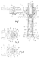
- Number 1 in Figure 1 indicates as a whole a fast-fit fastening device adjustable in length along an axis A, and in particular for fastening two components 2, 3 of a sanitary fixture a predetermined distance apart along axis A.
- device 1 is used to fix, a predetermined distance apart, a known control plate, of which only a frame portion 2 is shown, to a known lavatory flush tank, of which only a wall portion 3 is shown.
- Device 1 comprises a main member 5 having a seat 6 extending along axis A; a connecting rod 7 inserted and sliding inside seat 6 along axis A; and a lock member 8 for securing rod 7 inside seat 6.
- Main member 5, rod 7, and lock member 8 are all made of plastic.
- main member 5 comprises an elongated body 10 having seat 6, which is formed through two opposite surfaces 11, 12 of body 10 and bounded by two opposite end edges 13, 14.
- Main member 5 also has a through hole 15, parallel to seat 6, for insertion of a fastening member 16, e.g. a screw, by which to fix main member 5 to component 3.
- a fastening member 16 e.g. a screw
- seat 6 is substantially cylindrical, and has an inner lateral surface 17 from which two threaded, diametrically opposite projections 18 project towards each other and radially inwards of seat 6.
- Seat 6 therefore has two threaded sectors 19, defined by projections 18, alternating circumferentially with two smooth sectors 20 defined by the portions of surface 17 between the projections and having no threads.
- Threaded sectors 19 extend parallel to axis A inside seat 6, and each extend about an angle of roughly 90° (or less) with respect to the centre of seat 6.
- Seat 6 has an end portion 21 bounded by a radially outer annular shoulder facing surface 11 and edge 13.
- Main member 5 has a guide 23 for supporting lock member 8 in rotary manner about axis A.
- guide 23 comprises lateral-wall portions 24 defined by respective arms 25 (two diametrically opposite arms 25 in the example shown) projecting from surface 11, parallel to axis A, and curving about axis A; and opposite, facing, axial locating members 26 perpendicular to axis A. Locating members 26 are defined by edge 13 and, respectively, by two flexible teeth 27 at respective free ends of arms 25.
- guide 23 has a curved groove 28 formed in edge 13, extending about an angle of roughly 90°, and having two stop members 29, 30 located roughly 90° apart at respective opposite ends of groove 28 to limit rotation of lock member 8 between two predetermined limit positions, as explained below.
- Lock member 8 comprises a cylindrical ring 35 extending along axis A.
- Ring 35 has an inner axial through seat 36; and a radially outer collar 37 extending about ring 35 and defined by two opposite annular shoulders 38, 39.
- Ring 35 is housed inside guide 23, between arms 25, so as to rotate about axis A. More specifically, an end portion 40 of ring 35 is inserted for rotation inside end portion 21 of seat 6, shoulder 39 rests on edge 13, and shoulder 38 is engaged by teeth 27.
- Lock member 8 has a radially outer appendix 41 projecting axially from shoulder 39 and housed inside groove 28 to cooperate with stop members 29, 30.
- Lock member 8 also comprises a ring nut 42 integral with ring 35 and user-operated to rotate lock member 8 with respect to main member 5.
- Seat 36 is aligned with seat 6 along axis A, is in turn substantially cylindrical, and has an inner lateral surface 47 supporting two diametrically opposite, longitudinal projections 48, which extend parallel to axis A and project, towards each other, radially inwards of seat 36.
- Projections 48 are threaded and define respective threaded sectors 49, each of which extends about an angle of roughly 90° (or less), and which alternate circumferentially with smooth sectors 50 defined by portions of surface 47 with no threads.
- rod 7 comprises a substantially cylindrical stem 54 extending along axis A; and a head 55 having a cavity 56, and which is manoeuvred manually or by means of an appropriate tool inserted inside cavity 56.
- Stem 54 has an outer lateral surface 57 having two diametrically opposite, longitudinal threaded portions 59 alternating circumferentially with two longitudinal grooves 60.
- Stem 54 also has a number of cut-off sections 61 spaced along axis A, and by which to cut off surplus portions of rod 7, as required.
- Stem 54 is inserted through a hole 62 in component 2, and through seats 6, 36; and head 55 rests against a front surface 63 of component 2.
- Lock member 8 is movable with respect to main member 5 to selectively align and offset threaded sectors 19, 49 of seats 6, 36 along axis A. More specifically, as shown in Figures 7 and 8, lock member 8 rotates about axis A to selectively assume:
- lock member 8 corresponds to the two predetermined limit positions defined by stop members 29, 30 (and shown by the dash line in Figure 4).
- Device 1 operates as follows.
- Main member 5, complete with lock member 8 clicked inside guide 23 by virtue of flexible teeth 27, is fixed to component 3 ( Figure 1) ; lock member 8 is in the open position ( Figure 7), and rod 7, cut to length, if necessary, using cut-off sections 61, is inserted through hole 62 and seats 6, 36, with threaded portions 59 offset with respect to threaded sectors 19, 49 of seats 6, 36, i.e. with threaded sectors 19, 49 located along grooves 60.
- Grooves 60 are sized to avoid interfering with threaded sectors 19, 49, so that rod 7 slides freely along axis A inside the seats to permit fast rough adjustment of the length of device 1, i.e. of the distance between components 2 and 3 being fitted together.
- Appendix 41 rests against stop member 29.
- threaded sectors 19, 49 of seats 6, 36 are offset, and define a common threaded seat for rod 7, inside which rod 7 is screwed by means of threaded portions 59. Fine adjustment of the length of device 1 along axis A can be made by further clockwise rotation of rod 7.
Landscapes
- Engineering & Computer Science (AREA)
- General Engineering & Computer Science (AREA)
- Hydrology & Water Resources (AREA)
- Health & Medical Sciences (AREA)
- Public Health (AREA)
- Water Supply & Treatment (AREA)
- Life Sciences & Earth Sciences (AREA)
- Mechanical Engineering (AREA)
- Toilet Supplies (AREA)
- Connection Of Plates (AREA)
- Absorbent Articles And Supports Therefor (AREA)
- Clamps And Clips (AREA)
- Connector Housings Or Holding Contact Members (AREA)
Applications Claiming Priority (1)
| Application Number | Priority Date | Filing Date | Title |
|---|---|---|---|
| IT001550A ITMI20051550A1 (it) | 2005-08-05 | 2005-08-05 | Dispositivo di fissaggio rapido a lunghezza regolabile in particolare di una placca di coando di una apparecchiatura sanitaria |
Publications (2)
| Publication Number | Publication Date |
|---|---|
| EP1749940A1 true EP1749940A1 (de) | 2007-02-07 |
| EP1749940B1 EP1749940B1 (de) | 2008-07-30 |
Family
ID=37056404
Family Applications (1)
| Application Number | Title | Priority Date | Filing Date |
|---|---|---|---|
| EP06118492A Not-in-force EP1749940B1 (de) | 2005-08-05 | 2006-08-04 | Schnell- und längsverstellbare Befestigungsvorrichtung, insbesondere zur Befestigung einer Betätigungsplatte einer Sanitäranlage. |
Country Status (6)
| Country | Link |
|---|---|
| EP (1) | EP1749940B1 (de) |
| AT (1) | ATE403044T1 (de) |
| DE (1) | DE602006002002D1 (de) |
| ES (1) | ES2310891T3 (de) |
| IT (1) | ITMI20051550A1 (de) |
| RU (1) | RU2401912C2 (de) |
Cited By (1)
| Publication number | Priority date | Publication date | Assignee | Title |
|---|---|---|---|---|
| DE102017007588A1 (de) * | 2017-08-11 | 2019-02-14 | GROHEDAL Sanitärsysteme GmbH | Vorrichtung zur Befestigung eines Rahmens für eine Sanitäreinheit |
Families Citing this family (1)
| Publication number | Priority date | Publication date | Assignee | Title |
|---|---|---|---|---|
| WO2026022003A1 (de) * | 2024-07-23 | 2026-01-29 | Geberit International Ag | Lagerungsanordnung für eine betätigungseinheit eines unterputzspülkastens und schraubverbindung |
Citations (4)
| Publication number | Priority date | Publication date | Assignee | Title |
|---|---|---|---|---|
| US1451970A (en) * | 1920-02-03 | 1923-04-17 | Constant J Kryzanowsky | Temporary fastening |
| EP0273863A1 (de) * | 1986-12-11 | 1988-07-06 | Geberit AG | Bolzen und Gegenstück |
| EP0942183A2 (de) * | 1998-03-13 | 1999-09-15 | Oliveira & Irmao S.A. | Einstellbare Befestigungsvorrichtung |
| WO2003001068A2 (en) * | 2001-06-21 | 2003-01-03 | Yeong-Hoon Kim | Bolt and nut |
Family Cites Families (1)
| Publication number | Priority date | Publication date | Assignee | Title |
|---|---|---|---|---|
| SU1390319A1 (ru) * | 1986-04-28 | 1988-04-23 | Кишиневское Монтажное Управление N2 Треста "Молдсантехмонтаж" | Устройство дл монтажа на стене санитарного прибора |
-
2005
- 2005-08-05 IT IT001550A patent/ITMI20051550A1/it unknown
-
2006
- 2006-08-03 RU RU2006129214/03A patent/RU2401912C2/ru not_active IP Right Cessation
- 2006-08-04 ES ES06118492T patent/ES2310891T3/es active Active
- 2006-08-04 EP EP06118492A patent/EP1749940B1/de not_active Not-in-force
- 2006-08-04 AT AT06118492T patent/ATE403044T1/de not_active IP Right Cessation
- 2006-08-04 DE DE602006002002T patent/DE602006002002D1/de active Active
Patent Citations (4)
| Publication number | Priority date | Publication date | Assignee | Title |
|---|---|---|---|---|
| US1451970A (en) * | 1920-02-03 | 1923-04-17 | Constant J Kryzanowsky | Temporary fastening |
| EP0273863A1 (de) * | 1986-12-11 | 1988-07-06 | Geberit AG | Bolzen und Gegenstück |
| EP0942183A2 (de) * | 1998-03-13 | 1999-09-15 | Oliveira & Irmao S.A. | Einstellbare Befestigungsvorrichtung |
| WO2003001068A2 (en) * | 2001-06-21 | 2003-01-03 | Yeong-Hoon Kim | Bolt and nut |
Cited By (1)
| Publication number | Priority date | Publication date | Assignee | Title |
|---|---|---|---|---|
| DE102017007588A1 (de) * | 2017-08-11 | 2019-02-14 | GROHEDAL Sanitärsysteme GmbH | Vorrichtung zur Befestigung eines Rahmens für eine Sanitäreinheit |
Also Published As
| Publication number | Publication date |
|---|---|
| ES2310891T3 (es) | 2009-01-16 |
| RU2401912C2 (ru) | 2010-10-20 |
| ITMI20051550A1 (it) | 2007-02-06 |
| RU2006129214A (ru) | 2008-02-27 |
| DE602006002002D1 (de) | 2008-09-11 |
| ATE403044T1 (de) | 2008-08-15 |
| EP1749940B1 (de) | 2008-07-30 |
Similar Documents
| Publication | Publication Date | Title |
|---|---|---|
| US7513722B2 (en) | Collet collar stop for a drill bit | |
| US8407860B2 (en) | Apparatus for fastening a handle on a power tool | |
| US9066637B2 (en) | Shower rod with macro and micro adjustment | |
| US20080252086A1 (en) | Mechanism for Installing a Control Turning Handle of a Door Lock and Its Deinstalling Tool | |
| EP2752526A2 (de) | Vorrichtung zur Wandmontage einer Installationsstruktur für eine Sanitäranlagenbefestigung | |
| JP2019183629A (ja) | ピースの高さを調整するためのデバイス | |
| CN206616625U (zh) | 联接管道接管 | |
| CN111201380B (zh) | 接合设备 | |
| EP1750021B1 (de) | Sanitäranlagenstruktur mit einer einstellbaren Befestigungsvorrichtung | |
| EP1749940B1 (de) | Schnell- und längsverstellbare Befestigungsvorrichtung, insbesondere zur Befestigung einer Betätigungsplatte einer Sanitäranlage. | |
| CN108138988B (zh) | 龙头或减压器的打开和/或关闭状态的指示器 | |
| WO2010130874A1 (en) | Method and device for fixing a faucet to a mounting | |
| US10220502B2 (en) | Angle stop combination and tool handle | |
| PT1262266E (pt) | Dispositivo de fixação. | |
| KR20190008594A (ko) | 석재 설치용 앵커볼트 어셈블리 | |
| EP3514422A3 (de) | Adapter und verbindungen für aktuatoren und ventile | |
| US20150223898A1 (en) | Fast locking device for at least one tool on at least one guide element | |
| EP3070208A1 (de) | Betätigungsanordnung für eine bedieneinheit einer sanitären unterputzarmatur | |
| WO2007059535A2 (en) | Toggle clamp with manual horizontal and manual vertical adjustment | |
| EP1802817B1 (de) | Abflussrohr für eine sanitäreinrichtung. | |
| US20170106770A1 (en) | Connecting arrangement for a linkage of a vehicle seat, and vehicle seat | |
| EP2372173A1 (de) | Einstellungsvorrichtung zur Verwendung bei der Einstellung der Länge einer teleskopischen Anordnung | |
| CN221482739U (zh) | 一种阀结构 | |
| CN114681858A (zh) | 用于进行体育锻炼的单杠 | |
| EP1782924A1 (de) | Tiefenanschlagvorrichtung für kraftangetriebenes Werkzeug |
Legal Events
| Date | Code | Title | Description |
|---|---|---|---|
| PUAI | Public reference made under article 153(3) epc to a published international application that has entered the european phase |
Free format text: ORIGINAL CODE: 0009012 |
|
| AK | Designated contracting states |
Kind code of ref document: A1 Designated state(s): AT BE BG CH CY CZ DE DK EE ES FI FR GB GR HU IE IS IT LI LT LU LV MC NL PL PT RO SE SI SK TR |
|
| AX | Request for extension of the european patent |
Extension state: AL BA HR MK YU |
|
| 17P | Request for examination filed |
Effective date: 20070806 |
|
| 17Q | First examination report despatched |
Effective date: 20070905 |
|
| AKX | Designation fees paid |
Designated state(s): AT BE BG CH CY CZ DE DK EE ES FI FR GB GR HU IE IS IT LI LT LU LV MC NL PL PT RO SE SI SK TR |
|
| GRAP | Despatch of communication of intention to grant a patent |
Free format text: ORIGINAL CODE: EPIDOSNIGR1 |
|
| GRAS | Grant fee paid |
Free format text: ORIGINAL CODE: EPIDOSNIGR3 |
|
| GRAA | (expected) grant |
Free format text: ORIGINAL CODE: 0009210 |
|
| AK | Designated contracting states |
Kind code of ref document: B1 Designated state(s): AT BE BG CH CY CZ DE DK EE ES FI FR GB GR HU IE IS IT LI LT LU LV MC NL PL PT RO SE SI SK TR |
|
| REG | Reference to a national code |
Ref country code: GB Ref legal event code: FG4D |
|
| REG | Reference to a national code |
Ref country code: CH Ref legal event code: EP |
|
| REF | Corresponds to: |
Ref document number: 602006002002 Country of ref document: DE Date of ref document: 20080911 Kind code of ref document: P |
|
| REG | Reference to a national code |
Ref country code: IE Ref legal event code: FG4D |
|
| REG | Reference to a national code |
Ref country code: ES Ref legal event code: FG2A Ref document number: 2310891 Country of ref document: ES Kind code of ref document: T3 |
|
| PG25 | Lapsed in a contracting state [announced via postgrant information from national office to epo] |
Ref country code: IS Free format text: LAPSE BECAUSE OF FAILURE TO SUBMIT A TRANSLATION OF THE DESCRIPTION OR TO PAY THE FEE WITHIN THE PRESCRIBED TIME-LIMIT Effective date: 20081130 Ref country code: LT Free format text: LAPSE BECAUSE OF FAILURE TO SUBMIT A TRANSLATION OF THE DESCRIPTION OR TO PAY THE FEE WITHIN THE PRESCRIBED TIME-LIMIT Effective date: 20080730 Ref country code: NL Free format text: LAPSE BECAUSE OF FAILURE TO SUBMIT A TRANSLATION OF THE DESCRIPTION OR TO PAY THE FEE WITHIN THE PRESCRIBED TIME-LIMIT Effective date: 20080730 |
|
| PG25 | Lapsed in a contracting state [announced via postgrant information from national office to epo] |
Ref country code: PT Free format text: LAPSE BECAUSE OF FAILURE TO SUBMIT A TRANSLATION OF THE DESCRIPTION OR TO PAY THE FEE WITHIN THE PRESCRIBED TIME-LIMIT Effective date: 20081230 Ref country code: FI Free format text: LAPSE BECAUSE OF FAILURE TO SUBMIT A TRANSLATION OF THE DESCRIPTION OR TO PAY THE FEE WITHIN THE PRESCRIBED TIME-LIMIT Effective date: 20080730 Ref country code: LV Free format text: LAPSE BECAUSE OF FAILURE TO SUBMIT A TRANSLATION OF THE DESCRIPTION OR TO PAY THE FEE WITHIN THE PRESCRIBED TIME-LIMIT Effective date: 20080730 Ref country code: SI Free format text: LAPSE BECAUSE OF FAILURE TO SUBMIT A TRANSLATION OF THE DESCRIPTION OR TO PAY THE FEE WITHIN THE PRESCRIBED TIME-LIMIT Effective date: 20080730 Ref country code: AT Free format text: LAPSE BECAUSE OF FAILURE TO SUBMIT A TRANSLATION OF THE DESCRIPTION OR TO PAY THE FEE WITHIN THE PRESCRIBED TIME-LIMIT Effective date: 20080730 Ref country code: BG Free format text: LAPSE BECAUSE OF FAILURE TO SUBMIT A TRANSLATION OF THE DESCRIPTION OR TO PAY THE FEE WITHIN THE PRESCRIBED TIME-LIMIT Effective date: 20081030 |
|
| PG25 | Lapsed in a contracting state [announced via postgrant information from national office to epo] |
Ref country code: BE Free format text: LAPSE BECAUSE OF FAILURE TO SUBMIT A TRANSLATION OF THE DESCRIPTION OR TO PAY THE FEE WITHIN THE PRESCRIBED TIME-LIMIT Effective date: 20080730 Ref country code: MC Free format text: LAPSE BECAUSE OF NON-PAYMENT OF DUE FEES Effective date: 20080831 |
|
| PG25 | Lapsed in a contracting state [announced via postgrant information from national office to epo] |
Ref country code: EE Free format text: LAPSE BECAUSE OF FAILURE TO SUBMIT A TRANSLATION OF THE DESCRIPTION OR TO PAY THE FEE WITHIN THE PRESCRIBED TIME-LIMIT Effective date: 20080730 Ref country code: DK Free format text: LAPSE BECAUSE OF FAILURE TO SUBMIT A TRANSLATION OF THE DESCRIPTION OR TO PAY THE FEE WITHIN THE PRESCRIBED TIME-LIMIT Effective date: 20080730 |
|
| REG | Reference to a national code |
Ref country code: IE Ref legal event code: MM4A |
|
| PG25 | Lapsed in a contracting state [announced via postgrant information from national office to epo] |
Ref country code: SK Free format text: LAPSE BECAUSE OF FAILURE TO SUBMIT A TRANSLATION OF THE DESCRIPTION OR TO PAY THE FEE WITHIN THE PRESCRIBED TIME-LIMIT Effective date: 20080730 Ref country code: RO Free format text: LAPSE BECAUSE OF FAILURE TO SUBMIT A TRANSLATION OF THE DESCRIPTION OR TO PAY THE FEE WITHIN THE PRESCRIBED TIME-LIMIT Effective date: 20080730 Ref country code: CZ Free format text: LAPSE BECAUSE OF FAILURE TO SUBMIT A TRANSLATION OF THE DESCRIPTION OR TO PAY THE FEE WITHIN THE PRESCRIBED TIME-LIMIT Effective date: 20080730 |
|
| PLBE | No opposition filed within time limit |
Free format text: ORIGINAL CODE: 0009261 |
|
| STAA | Information on the status of an ep patent application or granted ep patent |
Free format text: STATUS: NO OPPOSITION FILED WITHIN TIME LIMIT |
|
| 26N | No opposition filed |
Effective date: 20090506 |
|
| PG25 | Lapsed in a contracting state [announced via postgrant information from national office to epo] |
Ref country code: IE Free format text: LAPSE BECAUSE OF NON-PAYMENT OF DUE FEES Effective date: 20080804 |
|
| PGFP | Annual fee paid to national office [announced via postgrant information from national office to epo] |
Ref country code: ES Payment date: 20090826 Year of fee payment: 4 |
|
| PG25 | Lapsed in a contracting state [announced via postgrant information from national office to epo] |
Ref country code: SE Free format text: LAPSE BECAUSE OF FAILURE TO SUBMIT A TRANSLATION OF THE DESCRIPTION OR TO PAY THE FEE WITHIN THE PRESCRIBED TIME-LIMIT Effective date: 20081030 |
|
| PG25 | Lapsed in a contracting state [announced via postgrant information from national office to epo] |
Ref country code: PL Free format text: LAPSE BECAUSE OF FAILURE TO SUBMIT A TRANSLATION OF THE DESCRIPTION OR TO PAY THE FEE WITHIN THE PRESCRIBED TIME-LIMIT Effective date: 20080730 |
|
| PG25 | Lapsed in a contracting state [announced via postgrant information from national office to epo] |
Ref country code: HU Free format text: LAPSE BECAUSE OF FAILURE TO SUBMIT A TRANSLATION OF THE DESCRIPTION OR TO PAY THE FEE WITHIN THE PRESCRIBED TIME-LIMIT Effective date: 20090131 Ref country code: LU Free format text: LAPSE BECAUSE OF NON-PAYMENT OF DUE FEES Effective date: 20080804 Ref country code: CY Free format text: LAPSE BECAUSE OF FAILURE TO SUBMIT A TRANSLATION OF THE DESCRIPTION OR TO PAY THE FEE WITHIN THE PRESCRIBED TIME-LIMIT Effective date: 20080730 |
|
| PG25 | Lapsed in a contracting state [announced via postgrant information from national office to epo] |
Ref country code: TR Free format text: LAPSE BECAUSE OF FAILURE TO SUBMIT A TRANSLATION OF THE DESCRIPTION OR TO PAY THE FEE WITHIN THE PRESCRIBED TIME-LIMIT Effective date: 20080730 |
|
| PG25 | Lapsed in a contracting state [announced via postgrant information from national office to epo] |
Ref country code: GR Free format text: LAPSE BECAUSE OF FAILURE TO SUBMIT A TRANSLATION OF THE DESCRIPTION OR TO PAY THE FEE WITHIN THE PRESCRIBED TIME-LIMIT Effective date: 20081031 |
|
| REG | Reference to a national code |
Ref country code: CH Ref legal event code: PL |
|
| GBPC | Gb: european patent ceased through non-payment of renewal fee |
Effective date: 20100804 |
|
| PG25 | Lapsed in a contracting state [announced via postgrant information from national office to epo] |
Ref country code: CH Free format text: LAPSE BECAUSE OF NON-PAYMENT OF DUE FEES Effective date: 20100831 Ref country code: LI Free format text: LAPSE BECAUSE OF NON-PAYMENT OF DUE FEES Effective date: 20100831 |
|
| REG | Reference to a national code |
Ref country code: FR Ref legal event code: ST Effective date: 20110502 |
|
| PG25 | Lapsed in a contracting state [announced via postgrant information from national office to epo] |
Ref country code: FR Free format text: LAPSE BECAUSE OF NON-PAYMENT OF DUE FEES Effective date: 20100831 |
|
| PG25 | Lapsed in a contracting state [announced via postgrant information from national office to epo] |
Ref country code: GB Free format text: LAPSE BECAUSE OF NON-PAYMENT OF DUE FEES Effective date: 20100804 |
|
| PGFP | Annual fee paid to national office [announced via postgrant information from national office to epo] |
Ref country code: FR Payment date: 20090908 Year of fee payment: 4 |
|
| REG | Reference to a national code |
Ref country code: ES Ref legal event code: FD2A Effective date: 20111019 |
|
| PG25 | Lapsed in a contracting state [announced via postgrant information from national office to epo] |
Ref country code: ES Free format text: LAPSE BECAUSE OF NON-PAYMENT OF DUE FEES Effective date: 20100805 |
|
| PGFP | Annual fee paid to national office [announced via postgrant information from national office to epo] |
Ref country code: IT Payment date: 20120827 Year of fee payment: 7 |
|
| PGFP | Annual fee paid to national office [announced via postgrant information from national office to epo] |
Ref country code: DE Payment date: 20130731 Year of fee payment: 8 |
|
| PG25 | Lapsed in a contracting state [announced via postgrant information from national office to epo] |
Ref country code: IT Free format text: LAPSE BECAUSE OF NON-PAYMENT OF DUE FEES Effective date: 20130804 |
|
| REG | Reference to a national code |
Ref country code: DE Ref legal event code: R119 Ref document number: 602006002002 Country of ref document: DE |
|
| REG | Reference to a national code |
Ref country code: DE Ref legal event code: R119 Ref document number: 602006002002 Country of ref document: DE Effective date: 20150303 |
|
| PG25 | Lapsed in a contracting state [announced via postgrant information from national office to epo] |
Ref country code: DE Free format text: LAPSE BECAUSE OF NON-PAYMENT OF DUE FEES Effective date: 20150303 |