EP1749943A2 - Module voûté - Google Patents
Module voûté Download PDFInfo
- Publication number
- EP1749943A2 EP1749943A2 EP06015996A EP06015996A EP1749943A2 EP 1749943 A2 EP1749943 A2 EP 1749943A2 EP 06015996 A EP06015996 A EP 06015996A EP 06015996 A EP06015996 A EP 06015996A EP 1749943 A2 EP1749943 A2 EP 1749943A2
- Authority
- EP
- European Patent Office
- Prior art keywords
- vault
- modules
- vault module
- module
- open
- Prior art date
- Legal status (The legal status is an assumption and is not a legal conclusion. Google has not performed a legal analysis and makes no representation as to the accuracy of the status listed.)
- Granted
Links
- SEQDDYPDSLOBDC-UHFFFAOYSA-N Temazepam Chemical compound N=1C(O)C(=O)N(C)C2=CC=C(Cl)C=C2C=1C1=CC=CC=C1 SEQDDYPDSLOBDC-UHFFFAOYSA-N 0.000 claims description 14
- 230000002787 reinforcement Effects 0.000 claims description 4
- 230000000295 complement effect Effects 0.000 claims 1
- 239000003351 stiffener Substances 0.000 abstract description 3
- 238000002788 crimping Methods 0.000 abstract 1
- XLYOFNOQVPJJNP-UHFFFAOYSA-N water Substances O XLYOFNOQVPJJNP-UHFFFAOYSA-N 0.000 description 19
- 239000002689 soil Substances 0.000 description 17
- 238000004140 cleaning Methods 0.000 description 4
- 230000008595 infiltration Effects 0.000 description 4
- 238000001764 infiltration Methods 0.000 description 4
- 238000012423 maintenance Methods 0.000 description 4
- 238000010079 rubber tapping Methods 0.000 description 4
- 239000000463 material Substances 0.000 description 3
- 239000012459 cleaning agent Substances 0.000 description 2
- 238000010276 construction Methods 0.000 description 2
- 239000002184 metal Substances 0.000 description 2
- 238000000034 method Methods 0.000 description 2
- 230000000737 periodic effect Effects 0.000 description 2
- 238000003825 pressing Methods 0.000 description 2
- 239000007787 solid Substances 0.000 description 2
- 238000010521 absorption reaction Methods 0.000 description 1
- 238000006243 chemical reaction Methods 0.000 description 1
- 238000006073 displacement reaction Methods 0.000 description 1
- 230000003670 easy-to-clean Effects 0.000 description 1
- 230000007613 environmental effect Effects 0.000 description 1
- ZINJLDJMHCUBIP-UHFFFAOYSA-N ethametsulfuron-methyl Chemical compound CCOC1=NC(NC)=NC(NC(=O)NS(=O)(=O)C=2C(=CC=CC=2)C(=O)OC)=N1 ZINJLDJMHCUBIP-UHFFFAOYSA-N 0.000 description 1
- 238000002360 preparation method Methods 0.000 description 1
- 230000000284 resting effect Effects 0.000 description 1
- 239000004576 sand Substances 0.000 description 1
- 239000000565 sealant Substances 0.000 description 1
- 238000007789 sealing Methods 0.000 description 1
- 238000003860 storage Methods 0.000 description 1
- 230000009747 swallowing Effects 0.000 description 1
Images



Classifications
-
- E—FIXED CONSTRUCTIONS
- E03—WATER SUPPLY; SEWERAGE
- E03F—SEWERS; CESSPOOLS
- E03F1/00—Methods, systems, or installations for draining-off sewage or storm water
- E03F1/002—Methods, systems, or installations for draining-off sewage or storm water with disposal into the ground, e.g. via dry wells
- E03F1/003—Methods, systems, or installations for draining-off sewage or storm water with disposal into the ground, e.g. via dry wells via underground elongated vaulted elements
Definitions
- the invention relates to a vault module for producing a seepage tunnel, which is formed from an arcuate wall, wherein the wall along its longitudinal edges each having a support edge for the flat support of the vault module on a planum, has in the direction of its longitudinal extension successively arranged stiffening ribs in the form of periodic surveys and is broken by a variety of seepage openings.
- Such a vault module is already out of the WO 03/100180 A2 known.
- a vault module is described, which can be assembled by means of various connection modules in rows to form a seepage tunnel, the tunnel can also run around curves and corners.
- such vault modules serve for drainage of land.
- the rainwater accumulating on roofs, balconies or even concrete or paved areas is usually supplied to the drain by means of the roof slope or a slope provided in the area to be drained, which in turn supplies the water to the sewer.
- the above-mentioned infiltration tunnels now provide a solution for creating both the space required for infiltration and the traffic areas such as roads and parking lots from the water.
- a planum ie a flat surface which is formed of gravel, is prepared first.
- the seepage tunnels made up of vault modules are placed and, if necessary, connected to the planum.
- the vaults created in this way are covered with soil and can then be entered, transplanted and even driven on.
- a supply line for filling the tunnel for example, by a connection to the gutter or a drain. Water collected in the tunnel will now be slowly and continuously released into the soil and will no longer be sent to the sewers and thus to the rivers. The prerequisite for this, however, is that the soil is also able to be infiltrated.
- the US 2003/0161685 A1 also describes such a vault module, in particular a method for their preparation.
- a wire frame is used according to this method, which works out the vault shape of a block of rigid, air-permeable material with a rotating movement.
- the present invention seeks to provide a vault module, with a much greater efficiency in terms of space requirements for the infiltration of a certain amount of water and at the same time a high degree of stability is ensured.
- the vault module according to the invention has along its longitudinal edges in each case a support edge on which the vault module can rest on the subgrade.
- the problem here is the pressure exerted from above through the soil on the open vault module, which would push the vault modules into the planum.
- the size of the support edges can not be arbitrarily increased for cost and practical reasons, since the edges tend to break in such a configuration.
- a corresponding contribution to the strength of the support edges make additional stiffening fingers, which support the support edges in their right-angled arrangement with respect to the wall against them.
- the bottom of an initially open vault module is formed by a bottom surface. Due to the resulting smooth floor surface, it is possible to drive the seepage tunnel with a camera and, if necessary, find faulty spots, blockages or other things of interest in the seepage tunnel.
- the bottom surface is connectable to the support edges, preferably by means of a tapping of the bottom surface with the support edges, so that the flanks of the vault module are additionally held against the pressure of the soil.
- the maintenance aspect is further supported by the fact that in the middle of the bottom surface of a channel runs, in which any deposits flow.
- Such a gutter is Easy to clean with appropriate cleaning equipment.
- the vault module As far as the vault module is placed directly on the subgrade, it is advantageous to additionally connect the relevant module to the ground by means of a ground anchor driven by one of the support edges. As a result, it is avoided that shifts occur when filling the seepage tunnel. After the seepage tunnels are mostly filled in with construction machinery, a large amount of material may press asymmetrically on one side of the modules and displace the pressure due to displacement. With the aid of the ground anchor, the modules fixed in this way are each held in at least one place.
- the vault module according to the invention is such that it can be combined with a second vault module as needed to form a double volume seepage tunnel.
- an open vault module is first placed on the planum so that the Arch vault to planum points.
- a second open vault module is placed with its support edges so that a tube, thus a closed vault module is formed.
- the vault modules offset in the longitudinal direction in order to achieve a greater degree of rigidity. Then, however, the offset must be equalized at both ends of the seepage tunnel.
- the interconnected support edges additionally avoid pushing apart the Gewölbedeem.
- anti-tipper means are provided on the convex vault side. These are essentially formed of a strut, which forms a straight resting edge, so that the module rests on this edge and is no longer movable on the arc rounding.
- the lower vault module has no seepage openings.
- Such a module can be used as a cistern so that water can be stored for removal.
- no bottom surface is used in a two-shell arrangement. Rather, a bottom plate is inserted into the lower module, which as well as the bottom plate is camera-driven. In addition, this floor plate can if necessary by means of margins to a gutter be reformed, which in turn can be easily cleaned with cleaning equipment.
- a cistern or a seepage tunnel can also be constructed in such a way that alternating vault modules with individually arranged open vault modules are combined to form an overall arrangement.
- a plurality of analogously structured layers can be combined with each other in this arrangement, wherein for reasons of stability, a staggered position to position arrangement is selected.
- the strength against the soil pressing from above can be improved as an alternative or in addition to a bottom surface, that means for cross-bracing between two opposite support edges are introduced so that even with greater pressure, the support edges can not be pushed apart due to the tension of the means for cross-bracing ,
- the transverse reinforcement can be realized both as a material strip connected to the support edges, and also as a chain or band.
- this means for cross-bracing is connected by means of a tapping with the support edges.
- This type of connection is on the one hand very durable, as by the use of solid, possibly metal, pin a long life is achieved, on the other hand, it is easy to open, should take place once a conversion or about an extension of a seepage tunnel.
- the bumps distributed periodically over the vaulted ridges of the module, from which the stiffening ribs are formed, are also internally supported by means of stiffening means. Since these directly oppose the pressure by their highlighted position, so a yielding of the wall is avoided.
- an overhead module rests with its inner wall surface on the module below. Where this is not possible, it rests on the stiffeners of the periodic elevations, which are perpendicular stand on the lower surface and thus can absorb the greatest pressure.
- vault modules for example terminal modules, can be closed with an end wall, which is preferably also equipped with a tongue and groove connection.
- the front wall recesses for example, provided for cleaning or camera handling of the seepage tunnel, which are preferably initially closed.
- the required recesses can be opened only when installing the end wall.
- the recesses can be used as inlet or as overflow of the modules.
- the modules are usually fed by water infiltrating from the surface of the earth and by water introduced from gutters or traffic areas, for example. While the former penetrates by itself through the vault walls, the latter must be introduced into the seepage tunnel by means of pipes and hoses.
- the housing module engages over an area which corresponds approximately to the transport surface of a Euro pallet.
- two vault modules can be laid one above the other stacked. This can be on site in a structurally simplest way double-walled seepage tunnel with correspondingly increased load capacity can be created.
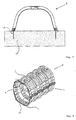
- FIG. 1 shows a vault module 1 for forming a seepage tunnel, which is formed from an arcuate wall 2.
- the vault module 1 is reinforced by means of stiffening ribs 5, which better support the pressure of the surrounding soil.
- the wall 2 is penetrated by a plurality of seepage openings 6 through which the rainwater to be seeped through the wall 2 can pass.
- a seepage tunnel is created by juxtaposing vault modules 1, which are connected together in series by means of a tongue and groove system 10.
- the area to be dewatered is first dug out and a subsurface 17 is created. This is fixed with gravel and carries the seepage tunnel.
- the vault modules 1 are placed on the planum 17 and optionally with anchored to this.
- the vault wall along its longitudinal edges supporting edges 4, which are supported with the vault module 1 with its surface.
- the pressure of the soil from above is additionally supported by means of the support edges 4.
- the rainwater to be seeped passes either via the seepage openings 6 or through supply lines into the seepage tunnel. There it can be stored first and then gradually released to the surrounding soil.
- Figure 2 shows how a vault module 1 can be greatly increased by assigning a second, along its longitudinal axis rotated by 180 °, vault module.
- the doubled capacity of the seepage tunnel is suitable for larger areas or larger amounts of water.
- the stability of the housing modules is ensured by means of anti-tilt device 7, which hold the modules 1,1 'in an upright position.
- the strength of the arrangement is additionally increased by means of transverse stiffening 8 in that the pressure of the soil from above, which would normally lead to a squeezing apart of the vault flanks is collected.
- FIG. 3 shows a sectional view of a single arch module 1, which is under attack by a bottom surface 14.
- the bottom surface 14 is camera accessible, so that the state the seepage tunnel is conveniently visible from outside the tunnel buried in the ground.
- a groove 15 is arranged so that flushed into the tunnel leaves, sand or the like when emptying the tunnel is preferably flushed into the channel 15.
- the channel 15 itself can be cleaned from the outside by means of cleaning devices which are pushed through the tunnel.
- the bottom surface is connected on both sides with the support edges of the vault module by means of a tap 9.
- the tapping 9 in contrast to about a screw has the advantage that it can be produced without tools.
- FIG. 4 shows a vault module 1 to which an end wall 16 is assigned.
- the end wall 16 limits the tunnel in its longitudinal extent so that on the one hand no soil can penetrate, but on the other hand, an orderly introduction of a camera or cleaning agents is possible.
- the front wall is associated with a maintenance opening 19, which is initially closed, but easy to open by means of a perforation.
- a maintenance opening 19 pipes or hoses for feeding a camera or cleaning agents can be connected.
- the end wall has inlet openings 20, through which, also by means of pipes or hoses, water collected on the site to be drained water is fed into the tunnel.
- Such inlet openings 20 are likewise arranged in each case on the vaulted back of the seepage tunnel between two stiffening ribs 5.
- FIG. 5 shows an arrangement of a plurality of seepage tunnels 3 into a pyramidal shape.
- Several side by side Seepage tunnels 3 are supplemented by a series of seepage tunnels arranged laterally offset.
- a simple and effective increase in capacity can also be achieved.
- taps 9 the overhead vault modules are firmly connected to the modules below.
- FIG. 6 shows a Euro pallet 18, on which a multiplicity of vault modules 1, 1 'are mounted.
- Figure 7 shows a sectional view through a vault module 1, which is connected by means of ground anchors 13 with a flat 17.
- the Planum 17 is prepared prior to the assembly of the seepage tunnels and consists of a surface as flat as possible of gravel.
- the vault modules placed thereon, which are assembled by means of their tongue and groove joints to form a seepage tunnel, can then be fixed using the ground anchors 13 in the planum 17, so that they can not move during the cover with soil.
- FIG. 8 shows an open vault module 1, to which a second, vault module 1 ', which is rotated by 180 ° along its longitudinal axis, is assigned.
- the two open vault modules 1, 1 ' are accordingly to a closed, here largely oval vault module.
- only the upper open vault module 1 has seepage openings 6 through which water enters the seepage tunnel can penetrate.
- the stability is enhanced by means of transverse stiffening 8 so that the seepage tunnel is not forced apart due to the weight of the surrounding soil or the water accumulated in the tunnel.
- the tunnel can be used as a cistern, which can also be filled or emptied by a submersible pump as needed.
- FIG. 9 shows a double-walled drainage tunnel which consists of at least two open vault modules 1, 1 '.
- the open arch modules 1, 1 ' stacked one inside the other, that the stiffening means of the stiffening ribs 12 of the above vault module 1 is largely perpendicular to the outside of the wall 2 of the underlying vault module 1' touches.
- Figures 10 and 11 show a special possible arrangement of the open vault modules 1, seen in cross section in alternation with closed vault modules 1 and 1 'laid.
- a plurality of correspondingly constructed layers can also be arranged one above the other, but each offset by a vault module.
Landscapes
- Health & Medical Sciences (AREA)
- Life Sciences & Earth Sciences (AREA)
- Engineering & Computer Science (AREA)
- Hydrology & Water Resources (AREA)
- Public Health (AREA)
- Water Supply & Treatment (AREA)
- Lining And Supports For Tunnels (AREA)
- Underground Structures, Protecting, Testing And Restoring Foundations (AREA)
Applications Claiming Priority (1)
| Application Number | Priority Date | Filing Date | Title |
|---|---|---|---|
| DE200520012192 DE202005012192U1 (de) | 2005-08-03 | 2005-08-03 | Gewölbemodul |
Publications (3)
| Publication Number | Publication Date |
|---|---|
| EP1749943A2 true EP1749943A2 (fr) | 2007-02-07 |
| EP1749943A3 EP1749943A3 (fr) | 2010-11-24 |
| EP1749943B1 EP1749943B1 (fr) | 2015-02-25 |
Family
ID=35404802
Family Applications (1)
| Application Number | Title | Priority Date | Filing Date |
|---|---|---|---|
| EP20060015996 Not-in-force EP1749943B1 (fr) | 2005-08-03 | 2006-08-01 | Système pour la fabrication d'un ou plusieurs tunnels de drainage |
Country Status (2)
| Country | Link |
|---|---|
| EP (1) | EP1749943B1 (fr) |
| DE (1) | DE202005012192U1 (fr) |
Cited By (3)
| Publication number | Priority date | Publication date | Assignee | Title |
|---|---|---|---|---|
| US10655316B1 (en) | 2019-04-05 | 2020-05-19 | Cur-Tech, LLC | Concrete galley water detention and release systems |
| US10900214B2 (en) | 2019-04-05 | 2021-01-26 | Cur-Tech, LLC | Concrete galley water detention and release systems |
| CN113669082A (zh) * | 2021-09-09 | 2021-11-19 | 中铁隧道集团二处有限公司 | 一种含中心水沟的隧道仰拱填充施工方法 |
Families Citing this family (4)
| Publication number | Priority date | Publication date | Assignee | Title |
|---|---|---|---|---|
| US7887256B2 (en) * | 2006-05-03 | 2011-02-15 | Joseph Miskovich | Smooth interior water collection and storage assembly |
| US8414222B2 (en) * | 2010-06-11 | 2013-04-09 | Robert J. DiTullio | Riser assembly for water storage chambers |
| DE102013225856A1 (de) * | 2013-12-13 | 2015-07-02 | Dr. Doll Holding Gmbh | Speichergewölbe für Flüssigkeiten |
| USD728825S1 (en) | 2014-03-12 | 2015-05-05 | Joseph Steve Miskovich | Construction conduit unit |
Citations (4)
| Publication number | Priority date | Publication date | Assignee | Title |
|---|---|---|---|---|
| EP0705946A2 (fr) | 1994-10-03 | 1996-04-10 | Infiltrator Systems, Inc. | Récipient d'infiltration avec paroi en forme de bande perforée |
| US20020044833A1 (en) | 2000-05-05 | 2002-04-18 | Kruger Kurt J. | Stormwater management system |
| US20030161685A1 (en) | 2002-02-26 | 2003-08-28 | Beaver Plastics Ltd. | Method of fabricating an insulated leaching chamber and an insulated leaching chamber |
| WO2003100180A2 (fr) | 2002-05-20 | 2003-12-04 | Infiltrator Systems, Inc. | Chambres de lixiviation assemblees par des raccords pivotants |
Family Cites Families (3)
| Publication number | Priority date | Publication date | Assignee | Title |
|---|---|---|---|---|
| US4523613A (en) * | 1980-07-01 | 1985-06-18 | Hancor, Inc. | Multi-layered corrugated conduit with "black-eye" like apertures |
| FR2801914B1 (fr) * | 1999-12-06 | 2002-10-18 | Gilles Giora | Structure de retention d'eau d'ecoulement |
| DE60323586D1 (de) * | 2002-10-31 | 2008-10-30 | Polypipe Civils Ltd | Grundwasserdrainagesystem |
-
2005
- 2005-08-03 DE DE200520012192 patent/DE202005012192U1/de not_active Expired - Lifetime
-
2006
- 2006-08-01 EP EP20060015996 patent/EP1749943B1/fr not_active Not-in-force
Patent Citations (5)
| Publication number | Priority date | Publication date | Assignee | Title |
|---|---|---|---|---|
| EP0705946A2 (fr) | 1994-10-03 | 1996-04-10 | Infiltrator Systems, Inc. | Récipient d'infiltration avec paroi en forme de bande perforée |
| EP0705946B1 (fr) | 1994-10-03 | 2002-01-30 | Infiltrator Systems, Inc. | Récipient d'infiltration avec paroi en forme de bande perforée |
| US20020044833A1 (en) | 2000-05-05 | 2002-04-18 | Kruger Kurt J. | Stormwater management system |
| US20030161685A1 (en) | 2002-02-26 | 2003-08-28 | Beaver Plastics Ltd. | Method of fabricating an insulated leaching chamber and an insulated leaching chamber |
| WO2003100180A2 (fr) | 2002-05-20 | 2003-12-04 | Infiltrator Systems, Inc. | Chambres de lixiviation assemblees par des raccords pivotants |
Cited By (3)
| Publication number | Priority date | Publication date | Assignee | Title |
|---|---|---|---|---|
| US10655316B1 (en) | 2019-04-05 | 2020-05-19 | Cur-Tech, LLC | Concrete galley water detention and release systems |
| US10900214B2 (en) | 2019-04-05 | 2021-01-26 | Cur-Tech, LLC | Concrete galley water detention and release systems |
| CN113669082A (zh) * | 2021-09-09 | 2021-11-19 | 中铁隧道集团二处有限公司 | 一种含中心水沟的隧道仰拱填充施工方法 |
Also Published As
| Publication number | Publication date |
|---|---|
| EP1749943A3 (fr) | 2010-11-24 |
| DE202005012192U1 (de) | 2005-11-10 |
| EP1749943B1 (fr) | 2015-02-25 |
Similar Documents
| Publication | Publication Date | Title |
|---|---|---|
| DE2835134C2 (de) | Rohr und System zum Be- und Entwässern des Erdreiches | |
| EP1757742B1 (fr) | Chambre d'infiltration avec canal de contrôle | |
| EP1291325B1 (fr) | Elément de caniveau pour la fabrication d'un caniveau pour la réception de l'eau de surface | |
| EP0322668A1 (fr) | Elément de construction pour l'érection d'un mur et mur érigé à l'aide de ces éléments | |
| EP1749943B1 (fr) | Système pour la fabrication d'un ou plusieurs tunnels de drainage | |
| CH589757A5 (en) | Box retaining wall for embankment protection - has crossed beams forming flexible assembly with smooth appearance | |
| DE19705824A1 (de) | Element zum Versickern einer Flüssigkeit | |
| DE19536896C2 (de) | Versickerungsrinnensystem | |
| DE4428482C2 (de) | Rinnenstein | |
| DE4326110A1 (de) | Ablaufrinne zur niveaugleichen Verlegung auf Flachdächern, insbesondere mit körnigen Substratschüttungen | |
| DE202009000040U1 (de) | Rigolenelement | |
| DE4102450C2 (de) | Ortsveränderliche Überdachung für Deponien | |
| EP2728076A2 (fr) | Canal pour l'évacuation des eaux de surface | |
| DE19955753B4 (de) | Wasserleitprofil | |
| EP4288611A1 (fr) | Système de drainage d'eau de surface et son procédé de production | |
| EP1522637B1 (fr) | Caniveau et élément d'angle pour caniveau | |
| DE8710405U1 (de) | Lärmschutzwand | |
| DE19721833C1 (de) | Salzhaldenabdeckung | |
| DE3519225A1 (de) | Verfahren zur errichtung von fuer hydraulische bergehalden benoetigten boeschungsstuetzkoerpern, sowie einrichtung zur durchfuehrung des verfahrens | |
| DE202023106435U1 (de) | Modul zur Begrünung von Dachflächen | |
| EP3626895B1 (fr) | Corps à rigoles destiné à la fabrication de rigoles souterrains de stockage des eaux pluviales | |
| AT520177B1 (de) | Trockenmauer und Zwischenstein hiefür | |
| EP1528168A2 (fr) | Rigole pour stockage intermédiaire de liquide, en particulier l'eau de pluie | |
| DE20306485U1 (de) | Steinkorb | |
| DE29612161U1 (de) | Stützmauerblock |
Legal Events
| Date | Code | Title | Description |
|---|---|---|---|
| PUAI | Public reference made under article 153(3) epc to a published international application that has entered the european phase |
Free format text: ORIGINAL CODE: 0009012 |
|
| AK | Designated contracting states |
Kind code of ref document: A2 Designated state(s): AT BE BG CH CY CZ DE DK EE ES FI FR GB GR HU IE IS IT LI LT LU LV MC NL PL PT RO SE SI SK TR |
|
| AX | Request for extension of the european patent |
Extension state: AL BA HR MK YU |
|
| PUAL | Search report despatched |
Free format text: ORIGINAL CODE: 0009013 |
|
| AK | Designated contracting states |
Kind code of ref document: A3 Designated state(s): AT BE BG CH CY CZ DE DK EE ES FI FR GB GR HU IE IS IT LI LT LU LV MC NL PL PT RO SE SI SK TR |
|
| AX | Request for extension of the european patent |
Extension state: AL BA HR MK RS |
|
| 17P | Request for examination filed |
Effective date: 20110524 |
|
| REG | Reference to a national code |
Ref country code: DE Ref legal event code: R108 |
|
| AKX | Designation fees paid |
Designated state(s): AT BE BG CH LI |
|
| RBV | Designated contracting states (corrected) |
Designated state(s): AT DE FR GB |
|
| REG | Reference to a national code |
Ref country code: DE Ref legal event code: R108 Ref document number: 502006014200 Country of ref document: DE Effective date: 20110720 Ref country code: DE Ref legal event code: R108 Effective date: 20110720 |
|
| 17Q | First examination report despatched |
Effective date: 20121107 |
|
| GRAP | Despatch of communication of intention to grant a patent |
Free format text: ORIGINAL CODE: EPIDOSNIGR1 |
|
| INTG | Intention to grant announced |
Effective date: 20141113 |
|
| GRAS | Grant fee paid |
Free format text: ORIGINAL CODE: EPIDOSNIGR3 |
|
| GRAA | (expected) grant |
Free format text: ORIGINAL CODE: 0009210 |
|
| AK | Designated contracting states |
Kind code of ref document: B1 Designated state(s): AT DE FR GB |
|
| REG | Reference to a national code |
Ref country code: GB Ref legal event code: FG4D Free format text: NOT ENGLISH |
|
| REG | Reference to a national code |
Ref country code: DE Ref legal event code: R096 Ref document number: 502006014200 Country of ref document: DE Effective date: 20150409 |
|
| REG | Reference to a national code |
Ref country code: AT Ref legal event code: REF Ref document number: 712134 Country of ref document: AT Kind code of ref document: T Effective date: 20150415 |
|
| REG | Reference to a national code |
Ref country code: DE Ref legal event code: R097 Ref document number: 502006014200 Country of ref document: DE |
|
| PLBE | No opposition filed within time limit |
Free format text: ORIGINAL CODE: 0009261 |
|
| STAA | Information on the status of an ep patent application or granted ep patent |
Free format text: STATUS: NO OPPOSITION FILED WITHIN TIME LIMIT |
|
| 26N | No opposition filed |
Effective date: 20151126 |
|
| REG | Reference to a national code |
Ref country code: FR Ref legal event code: PLFP Year of fee payment: 11 |
|
| REG | Reference to a national code |
Ref country code: FR Ref legal event code: PLFP Year of fee payment: 12 |
|
| PGFP | Annual fee paid to national office [announced via postgrant information from national office to epo] |
Ref country code: GB Payment date: 20170824 Year of fee payment: 12 Ref country code: DE Payment date: 20170823 Year of fee payment: 12 Ref country code: FR Payment date: 20170823 Year of fee payment: 12 |
|
| PGFP | Annual fee paid to national office [announced via postgrant information from national office to epo] |
Ref country code: AT Payment date: 20170821 Year of fee payment: 12 |
|
| REG | Reference to a national code |
Ref country code: DE Ref legal event code: R119 Ref document number: 502006014200 Country of ref document: DE |
|
| REG | Reference to a national code |
Ref country code: AT Ref legal event code: MM01 Ref document number: 712134 Country of ref document: AT Kind code of ref document: T Effective date: 20180801 |
|
| GBPC | Gb: european patent ceased through non-payment of renewal fee |
Effective date: 20180801 |
|
| PG25 | Lapsed in a contracting state [announced via postgrant information from national office to epo] |
Ref country code: AT Free format text: LAPSE BECAUSE OF NON-PAYMENT OF DUE FEES Effective date: 20180801 |
|
| PG25 | Lapsed in a contracting state [announced via postgrant information from national office to epo] |
Ref country code: DE Free format text: LAPSE BECAUSE OF NON-PAYMENT OF DUE FEES Effective date: 20190301 |
|
| PG25 | Lapsed in a contracting state [announced via postgrant information from national office to epo] |
Ref country code: FR Free format text: LAPSE BECAUSE OF NON-PAYMENT OF DUE FEES Effective date: 20180831 |
|
| PG25 | Lapsed in a contracting state [announced via postgrant information from national office to epo] |
Ref country code: GB Free format text: LAPSE BECAUSE OF NON-PAYMENT OF DUE FEES Effective date: 20180801 |