EP1749968B1 - Turbinenschaufeln - Google Patents
Turbinenschaufeln Download PDFInfo
- Publication number
- EP1749968B1 EP1749968B1 EP06253935A EP06253935A EP1749968B1 EP 1749968 B1 EP1749968 B1 EP 1749968B1 EP 06253935 A EP06253935 A EP 06253935A EP 06253935 A EP06253935 A EP 06253935A EP 1749968 B1 EP1749968 B1 EP 1749968B1
- Authority
- EP
- European Patent Office
- Prior art keywords
- neck portion
- platform
- turbine blade
- root
- additional material
- Prior art date
- Legal status (The legal status is an assumption and is not a legal conclusion. Google has not performed a legal analysis and makes no representation as to the accuracy of the status listed.)
- Active
Links
Images




Classifications
-
- F—MECHANICAL ENGINEERING; LIGHTING; HEATING; WEAPONS; BLASTING
- F01—MACHINES OR ENGINES IN GENERAL; ENGINE PLANTS IN GENERAL; STEAM ENGINES
- F01D—NON-POSITIVE DISPLACEMENT MACHINES OR ENGINES, e.g. STEAM TURBINES
- F01D5/00—Blades; Blade-carrying members; Heating, heat-insulating, cooling or antivibration means on the blades or the members
- F01D5/30—Fixing blades to rotors; Blade roots ; Blade spacers
- F01D5/3007—Fixing blades to rotors; Blade roots ; Blade spacers of axial insertion type
-
- F—MECHANICAL ENGINEERING; LIGHTING; HEATING; WEAPONS; BLASTING
- F01—MACHINES OR ENGINES IN GENERAL; ENGINE PLANTS IN GENERAL; STEAM ENGINES
- F01D—NON-POSITIVE DISPLACEMENT MACHINES OR ENGINES, e.g. STEAM TURBINES
- F01D5/00—Blades; Blade-carrying members; Heating, heat-insulating, cooling or antivibration means on the blades or the members
- F01D5/12—Blades
- F01D5/14—Form or construction
- F01D5/147—Construction, i.e. structural features, e.g. of weight-saving hollow blades
-
- F—MECHANICAL ENGINEERING; LIGHTING; HEATING; WEAPONS; BLASTING
- F05—INDEXING SCHEMES RELATING TO ENGINES OR PUMPS IN VARIOUS SUBCLASSES OF CLASSES F01-F04
- F05D—INDEXING SCHEME FOR ASPECTS RELATING TO NON-POSITIVE-DISPLACEMENT MACHINES OR ENGINES, GAS-TURBINES OR JET-PROPULSION PLANTS
- F05D2230/00—Manufacture
- F05D2230/10—Manufacture by removing material
-
- F—MECHANICAL ENGINEERING; LIGHTING; HEATING; WEAPONS; BLASTING
- F05—INDEXING SCHEMES RELATING TO ENGINES OR PUMPS IN VARIOUS SUBCLASSES OF CLASSES F01-F04
- F05D—INDEXING SCHEME FOR ASPECTS RELATING TO NON-POSITIVE-DISPLACEMENT MACHINES OR ENGINES, GAS-TURBINES OR JET-PROPULSION PLANTS
- F05D2230/00—Manufacture
- F05D2230/90—Coating; Surface treatment
-
- F—MECHANICAL ENGINEERING; LIGHTING; HEATING; WEAPONS; BLASTING
- F05—INDEXING SCHEMES RELATING TO ENGINES OR PUMPS IN VARIOUS SUBCLASSES OF CLASSES F01-F04
- F05D—INDEXING SCHEME FOR ASPECTS RELATING TO NON-POSITIVE-DISPLACEMENT MACHINES OR ENGINES, GAS-TURBINES OR JET-PROPULSION PLANTS
- F05D2240/00—Components
- F05D2240/80—Platforms for stationary or moving blades
-
- F—MECHANICAL ENGINEERING; LIGHTING; HEATING; WEAPONS; BLASTING
- F05—INDEXING SCHEMES RELATING TO ENGINES OR PUMPS IN VARIOUS SUBCLASSES OF CLASSES F01-F04
- F05D—INDEXING SCHEME FOR ASPECTS RELATING TO NON-POSITIVE-DISPLACEMENT MACHINES OR ENGINES, GAS-TURBINES OR JET-PROPULSION PLANTS
- F05D2250/00—Geometry
- F05D2250/70—Shape
-
- F—MECHANICAL ENGINEERING; LIGHTING; HEATING; WEAPONS; BLASTING
- F05—INDEXING SCHEMES RELATING TO ENGINES OR PUMPS IN VARIOUS SUBCLASSES OF CLASSES F01-F04
- F05D—INDEXING SCHEME FOR ASPECTS RELATING TO NON-POSITIVE-DISPLACEMENT MACHINES OR ENGINES, GAS-TURBINES OR JET-PROPULSION PLANTS
- F05D2250/00—Geometry
- F05D2250/70—Shape
- F05D2250/71—Shape curved
-
- F—MECHANICAL ENGINEERING; LIGHTING; HEATING; WEAPONS; BLASTING
- F05—INDEXING SCHEMES RELATING TO ENGINES OR PUMPS IN VARIOUS SUBCLASSES OF CLASSES F01-F04
- F05D—INDEXING SCHEME FOR ASPECTS RELATING TO NON-POSITIVE-DISPLACEMENT MACHINES OR ENGINES, GAS-TURBINES OR JET-PROPULSION PLANTS
- F05D2260/00—Function
- F05D2260/94—Functionality given by mechanical stress related aspects such as low cycle fatigue [LCF] of high cycle fatigue [HCF]
- F05D2260/941—Functionality given by mechanical stress related aspects such as low cycle fatigue [LCF] of high cycle fatigue [HCF] particularly aimed at mechanical or thermal stress reduction
Definitions
- the present invention relates to an improved design for a turbine blade to be used in a gas turbine engine
- turbine blades 10 typically used in gas turbine engines include a platform 12, an airfoil 14 extending radially from a first side of the platform, and an attachment or root portion 16 extending from a second side or underside of the platform.
- the root portion 16 typically includes a dovetail portion with a plurality of serrations and a neck portion between the dovetail portion and the underside of the platform.
- the airfoil 14 may overhang the footprint of the root portion 16.
- the neck portion of the attachment or root portion 16 begins just beneath the pocket structure 18 and forms a limiting structure in the sense that significant stresses act in this region - stresses which if not dealt with properly could be the source of cracks and other potential failure modes. Balancing stress concentrations between suction and pressure sides of the neck portion and the stress on the turbine airfoil 14 is highly desirable.
- US-5435694 discloses a stress relieving mount for an axial blade.
- the root axial length of the root portion 16 is generally shorter than the airfoil chord axial component. Most low pressure turbine airfoils also have shorter attachment root neck lengths. The overhung airfoil and short neck length create a load path that will concentrate stress in the root in most cases. This is exemplified in FIG. 2 . In certain cases, these stresses are unacceptable and a potential source of cracks.
- the traditional solution to this problem is to increase root axial length, width, and enlarge serration sizes. This traditional solution requires a new disk design and increases weight.
- the turbine blades of the present invention better balance the stress concentrations between the lower stress and higher stress sides of the turbine blade root neck.
- a turbine blade which broadly comprises a platform, an airfoil radially extending from the platform, an attachment portion including a neck portion with a rear root face and a root higher stress side, and means for dispersing strain in a region where the airfoil overhangs the neck portion.
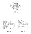
- FIGS. 3 through 5 illustrate a turbine blade 100 in accordance with the present invention.
- the turbine blade 100 has a platform 102, an airfoil 104 radially extending from a first side 106 of the platform 102, and an attachment or root portion 108 extending from a second side 110 of the platform 102.
- a pocket structure 112 is formed in the sides of the platform 102. Just below the pocket structure 112, there is a neck portion 114 that forms part of the root portion 108.
- the root portion 108 also has a dovetail portion 116 that is used to join the turbine blade 100 to a rotating member (not shown) such as a rotating disk.
- the root portion 108 has a front root face 111 and a rear root face 122.
- the airfoil 104 overhangs the footprint 118 of the root portion 108.
- stresses and strain which are caused by the overhung airfoil 104 are dispersed over an increased area.
- One part of this increased area is formed by additional material 120 along the rear root face 122.
- the additional material 120 may be a cast material or a deposited material and may be the same material as the material forming the turbine blade 100 or may be a material which is compatible with the material forming the turbine blade 100.
- the rear root face 122 has a planar portion 125 extending from an edge or a surface 127.
- the leading edge 129 of the additional material 120 begins at a point spaced from the surface 127.
- the leading edge 129 is preferably arcuately spaced and extends from a first side 133 of the rear root face 122 to a second or opposite side 135 of the rear root face 122.
- the additional material 120 increases in thickness as it goes from the leading edge 129 to a point where it intersects the second side 110 of the platform 102. This causes the rear root face 122, at the point where it contacts the platform 102 to have a curved, non-linear shape 137 as can be seen in FIG. 8 .
- the increased area for dispersing the stresses and strains may include a compound fillet 124 beginning at a point 139 at about 88% of the distance between the forward front root face 111 and the trailing edge 128 of the platform 102.
- the compound fillet 124 is preferably located on the higher stress side 126 of the platform 102.
- the higher stress side 126 is the pressure side of the platform.
- the compound fillet 124 may be a cast structure formed from the same material as that forming the turbine blade 100 or may be a deposited material formed from the same material as, or from a different material compatible with, the material forming the turbine blade 100.
- the compound fillet 124 may be machined if desired.
- the root neck portion 114 preferably has a planar or substantially planar portion 202 extending from the front root face 111 to a point 204 about midway of the distance from the front root face 111 to the trailing edge 128.
- the upper edge 200 then has an arcuately shaped transition zone 206 which extends from the point 204 to the starting point 139 of the compound fillet 124.
- the compound fillet 124 may then arcuately extend from the point 139 to a point near, or at, the intersection of the higher stress side 126 of the platform and the trailing edge 128 of the platform.
- the compound fillet 124 is three dimensional and rises from the planar surface of the second side 110 of the platform 102 to an elevated ridge 210 where it intersects the additional material 120.
- the load may be more dispersed between the pressure side and suction side serrations 212 and 214 through a larger area.
- the root neck portion 114 is tapered axially producing increased root thickness towards the rear of the root portion 108. This assists in reducing the stiffness in the center of the neck portion 114.
- the turbine blade 100 has a maximum stress life limiting section 130 which is an uppermost section of the neck portion 114 just beneath the platform 102.
- the stress concentrations caused by the overhung airfoil 104 should be balanced between the lower stress side 132 (typically the suction side) and the higher stress side 134 (typically the pressure side) of the limiting section 130.
- the stress load may be redistributed by adjusting the moment of the volume above the limiting section center of gravity (CG) 140 relative to the peak stress area CG 142 without adjusting the volume of the portion of the turbine blade 100 above the limiting section 130. This is done by adjusting the area CG 142 which affects the moment caused by the volume of the portion of the turbine blade above the limiting section. Increasing the moment to the lower stress side greatly reduces the stress on the higher or peak stress side.
- CG center of gravity
- the desired reduction in stress on the peak stress side may be accomplished by taking material away from the lower stress side (suction side) 144 of the limiting section 130 and/or by adding material on the high stress side (pressure side) 146. This is illustrated in FIG. 8 and results in the neck portion 114 being asymmetric.
- the change in location of the cg of area 142 and the cg of volume above the limiting section 140 can be seen in FIGS. 6 and 7 . It can be seen that the distance D2 between the cg of volume 140 and the cg of area 142 in FIG. 7 is greater than the distance D1 between cg of volume 140 and the cg of area 142 in FIG. 6 . This indicates the increase in moment to the lower stress side 144.
- approximately 0.005 inches (0.127 mm)of material may be removed from the side 144 in one or more benign stress areas.
- additional material giving rise to an increase of 0.020 inches (0.508 mm) may be made to the higher stress or pressure side 146.
- the additional material may comprise a material which is identical to or compatible with the material forming the turbine blade 100 and may take the form of the compound fillet 124 and the transition zone 206 from the planar or substantially planar portion 202 to the compound fillet 124.
- this additional material may be a cast material or may be deposited after the turbine blade 100 has been formed.
- the material removal from the lower stress or suction side 144 should be balanced with total P (force)/A (area) stress on the airfoil portion 104. Further, the bending moment is preferably moved more towards one side in such a way as to reduce the peak stress on the other side.
- the asymmetric nature of the neck portion 114 as a result of the aforementioned modifications is shown in FIG. 8 .
- the asymmetric neck portion 114 of the present invention has particular utility on blades with broach angles.
- FIG. 10 illustrates the stresses on the pressure side of a prior art turbine blade, particularly at the pressure side cast pocket 300.
- FIG. 11 illustrates the reduced stresses caused by the present invention. As can be seen from FIG. 11 , the stress at the pressure side cast pocket 300 has been reduced by 42%. The stress at the pressure side machined fillet 302 has been reduced by 31%.
Landscapes
- Engineering & Computer Science (AREA)
- Mechanical Engineering (AREA)
- General Engineering & Computer Science (AREA)
- Architecture (AREA)
- Turbine Rotor Nozzle Sealing (AREA)
Claims (15)
- Verfahren zum Bereitstellen einer Turbinenschaufel (100), die ausgeglichene Belastungskonzentrationen zwischen Saugseite und Druckseite (144, 146) aufweist, umfassend den Schritt:Ausbilden einer Turbinenschaufel aufweisend eine Plattform (102), einen Anbringungsbereich (108), der einen Halsbereich (114) unterhalb der Plattform (102) aufweist, und einen Strömungsprofilbereich (104), der sich radial von der Plattform (102) erstreckt und die Grundfläche (118) des Anbringungsbereichs (108) überragt und einen Begrenzungsabschnitt (130) an dem obersten Abschnitt des Halsbereichs (114) gleich unterhalb der Plattform (102);Anpassen eines Moments von Volumen oberhalb des Begrenzungsabschnitt-Schwerpunkts (140) hin zu einer Seite geringerer Belastung des Halsbereichs (114);wobei der Anpassungsschritt Entfernen von Material ausschließlich von der Seite geringerer Belastung des Begrenzungsabschnitts (130) und/oder Hinzufügen von Material zu der Seite höherer Belastung des Halsbereichs (114) umfasst.
- Verfahren nach Anspruch 1, wobei der Anpassungsschritt Abnehmen von Material von der Seite geringerer Belastung und Hinzufügen von Material zu der Seite höherer Belastung des Halsbereichs (114) umfasst, um dadurch einen asymmetrischen Halsbereich auszubilden.
- Verfahren nach Anspruch 2, wobei der Anpassungsschritt Abnehmen von Material von einer Saugseite des Halsbereichs (114) und Hinzufügen von Material zu einer Druckseite des Halsbereichs (114) umfasst.
- Verfahren nach einem der vorangehenden Ansprüche, des Weiteren umfassend Verteilen von Spannung in einem Bereich, in dem das Strömungsprofil (104) den Halsbereich (114) überragt.
- Verfahren nach Anspruch 4, wobei der Spannungsverteilungsschritt Hinzufügen von zusätzlichem Material (120) an eine hintere Wurzelfläche (122) des Anbringungsbereichs (108) umfasst, wobei die hintere Wurzelfläche (122) einen im Wesentlichen ebenen Bereich (125) an einem ersten Ende aufweist, und wobei der Aufbringungsschritt Hinzufügen des zusätzlichen Materials (120) beginnend an einem von dem ersten Ende beabstandeten Punkt umfasst, und wobei der Hinzufügungsschritt Hinzufügen des zusätzlichen Materials (120) umfasst, so dass das zusätzliche Material in der Dicke von dem zu dem ersten Ende beabstandeten Punkt zu einer Fläche der Plattform (102) ansteigt.
- Verfahren nach Anspruch 4 oder 5, wobei der Spannungsverteilungsschritt Ausbilden einer Verbundauskehlung (124) auf einer Hinterkante der Seite höherer Belastung einer Wurzel des Anbringungsbereichs (108) umfasst, wobei der Ausbildungsschritt das Ausbilden einer Halsbereichkante, die einen ebenen Bereich aufweist, eines bogenförmig geformten Übergangsbereichs (206), der an den ebenen Bereich angebracht ist, und Hinzufügen von Material an einem Ende des Übergangsbereichs (206) umfasst, um die Verbundauskehlung (124) auszubilden, und wobei der Ausbildungsschritt des Weiteren Entfernen von Material von einer Seite geringerer Belastung des Halsbereichs (114) beinhaltet, um einen asymmetrischen Halsbereich auszubilden.
- Turbinenschaufel (100) umfassend:eine Plattform (102);einen Anbringungsbereich (108), der einen Wurzelhalsbereich (114) umfasst, der eine Seite höherer Belastung und eine Seite geringerer Belastung aufweist;ein Strömungsprofil (104), das sich radial von der Plattform (102) erstreckt und den Grundriss (118) des Anbringungsbereichs (108) überragt;einen Begrenzungsabschnitt (130) an einem obersten Abschnitt des Wurzelhalsbereichs (114) gerade unterhalb der Plattform (102);dadurch gekennzeichnet, dass:der Wurzelhalsbereich (114) ein asymmetrischer Wurzelhalsbereich (114) ist und ein Moment von Volumen oberhalb des Begrenzungsabschnitt-Schwerpunkts (140) relativ zu einem Schwerpunkt des Belastungshöchstwertbereichs hin zu der Seite geringerer Belastung des asymmetrischen Wurzelhalsbereichs (114) anpasst: undder asymmetrische Wurzelhalsbereich (114) durch ein Material (120) ausgebildet ist, das der Seite höherer Belastung des Halsbereichs (114) hinzugefügt ist und/oder durch ausschließlich von einer Seite geringerer Belastung des Halsbereichs (114) entferntem Material.
- Turbinenschaufel nach Anspruch 7, wobei die Seite höherer Belastung eine Druckseite umfasst und die Seite geringerer Belastung eine Saugseite umfasst.
- Turbinenschaufel nach Anspruch 7 oder 8, wobei der Anbringungsbereich (108) eine vordere Wurzelfläche (111) aufweist und der Wurzelhalsbereich (114) eine Kante mit einem ebenen Bereich (202), der sich von der vorderen Wurzelfläche (111) erstreckt, einen bogenförmig geformten Übergangsbereich (206), der benachbart eines Endes der vorderen Wurzelfläche angeordnet ist, und eine Verbundauskehlung (124) aufweist, die sich von einem Ende des Übergangsbereichs (206) erstreckt.
- Turbinenschaufel nach Anspruch 9, wobei die Plattform (102) eine Hinterkante (128) aufweist und die Verbundauskehlung (124) eine gekrümmte Fläche aufweist, die sich von dem Ende des Übergangsbereichs (206) zu einem Punkt nahe einer Überschneidung der Seite höheren Drucks (126) und der Hinterkante (128) erstreckt, und wobei die Verbundauskehlung (124) in der Höhe von einem Punkt aus ansteigt, an dem die Verbundauskehlung (124) sich mit einer Fläche der Plattform (102) und einem erhöhten Vorsprung (210) überschneidet.
- Turbinenschaufel nach einem der Ansprüche 7 bis 10, des Weiteren umfassend Mittel zum Verteilen von Spannung in einem Bereich, in dem das Strömungsprofil (104) den Halsbereich (114) überragt.
- Turbinenschaufel nach Anspruch 11, wobei der Anbringungsbereich (108) eine hintere Wurzelfläche (122) aufweist, und das Spannungsverteilungsmittel zusätzliches Material (120) umfasst, das auf der hinteren Wurzelfläche (122) ausgebildet ist, wobei die Spannungsverteilungsmittel des Weiteren eine Verbundauskehlung (124) an einem Endbereich einer Seite höheren Drucks auf der Plattform (102) umfasst, wobei die hintere Wurzelfläche (122) einen ebenen Bereich (125) aufweist und das zusätzliche Material eine Vorderkante (129) aufweist, die von einer Kante des ebenen Bereichs (125) beabstandet ist, wobei die Vorderkante (129) bogenförmig geformt ist, und wobei das zusätzliche Material (120) in der Dicke von der Vorderkante (129) aus zu einem Punkt benachbart einer Fläche der Plattform (102) ansteigt.
- Turbinenschaufel nach Anspruch 11, wobei der Anbringungsbereich (108) eine hintere Wurzelfläche (122) aufweist und das Spannungsverteilungsmittel zusätzliches Material (120) auf der hinteren Wurzelfläche (122) umfasst.
- Turbinenschaufel nach Anspruch 13, wobei die hintere Wurzelfläche (122) einen ebenen Bereich (125), der an einem ersten Ende beginnt, aufweist und das zusätzliche Material (120) sich von einer Vorderkante (129), die von dem ersten Ende beabstandet ist, zu einem Ort, an dem das zusätzliche Material (120) eine Unterseite der Plattform (102) schneidet, erstreckt, und wobei das zusätzliche Material (120) in der Dicke von der Vorderkante zu dem Ort ansteigt.
- Turbinenschaufel nach Anspruch 13 oder 14, wobei das Spannungsverteilungsmittel des Weiteren eine Verbundauskehlung an einer Hinterkante einer Seite höherer Belastung (128) des Anbringungsbereichs (108) aufweist, wobei die Verbundauskehlung (124) einen Vorsprung (210) aufweist und die Verbundauskehlung (124) in der Dicke von einem Punkt, an dem die Verbundauskehlung (124) auf eine Unterseite der Plattform (102) trifft, zu dem Vorsprung (210) ansteigt, und wobei der Anbringungsbereich (108) einen ebenen Abschnitt (202) aufweist und das Spannungsverteilungsmittel des Weiteren einen gebogenen Übergangsabschnitt (206) zwischen dem ebenen Abschnitt (202) und der Verbundauskehlung (124) umfasst.
Applications Claiming Priority (1)
| Application Number | Priority Date | Filing Date | Title |
|---|---|---|---|
| US11/197,152 US7549846B2 (en) | 2005-08-03 | 2005-08-03 | Turbine blades |
Publications (3)
| Publication Number | Publication Date |
|---|---|
| EP1749968A2 EP1749968A2 (de) | 2007-02-07 |
| EP1749968A3 EP1749968A3 (de) | 2010-04-28 |
| EP1749968B1 true EP1749968B1 (de) | 2012-03-14 |
Family
ID=37397446
Family Applications (1)
| Application Number | Title | Priority Date | Filing Date |
|---|---|---|---|
| EP06253935A Active EP1749968B1 (de) | 2005-08-03 | 2006-07-27 | Turbinenschaufeln |
Country Status (6)
| Country | Link |
|---|---|
| US (1) | US7549846B2 (de) |
| EP (1) | EP1749968B1 (de) |
| JP (1) | JP2007040296A (de) |
| CN (1) | CN1908380A (de) |
| AU (1) | AU2006202238A1 (de) |
| SG (1) | SG130089A1 (de) |
Cited By (1)
| Publication number | Priority date | Publication date | Assignee | Title |
|---|---|---|---|---|
| US9353629B2 (en) | 2012-11-30 | 2016-05-31 | Solar Turbines Incorporated | Turbine blade apparatus |
Families Citing this family (19)
| Publication number | Priority date | Publication date | Assignee | Title |
|---|---|---|---|---|
| US20080317597A1 (en) * | 2007-06-25 | 2008-12-25 | General Electric Company | Domed tip cap and related method |
| USD611510S1 (en) * | 2007-08-28 | 2010-03-09 | Alstom Technology Ltd. | Turbo machine blade platform |
| USD586831S1 (en) * | 2007-08-28 | 2009-02-17 | Alstom Technology Ltd. | Turbo machine double blade and platform |
| US8122601B2 (en) * | 2008-04-15 | 2012-02-28 | United Technologies Corporation | Methods for correcting twist angle in a gas turbine engine blade |
| US9840931B2 (en) * | 2008-11-25 | 2017-12-12 | Ansaldo Energia Ip Uk Limited | Axial retention of a platform seal |
| US8608447B2 (en) * | 2009-02-19 | 2013-12-17 | Rolls-Royce Corporation | Disk for turbine engine |
| US8834123B2 (en) * | 2009-12-29 | 2014-09-16 | Rolls-Royce Corporation | Turbomachinery component |
| DE102010004854A1 (de) * | 2010-01-16 | 2011-07-21 | MTU Aero Engines GmbH, 80995 | Laufschaufel für eine Strömungsmaschine und Strömungsmaschine |
| FR2963383B1 (fr) * | 2010-07-27 | 2016-09-09 | Snecma | Aube de turbomachine, rotor, turbine basse pression et turbomachine equipes d'une telle aube |
| US9617860B2 (en) * | 2012-12-20 | 2017-04-11 | United Technologies Corporation | Fan blades for gas turbine engines with reduced stress concentration at leading edge |
| EP2971553B1 (de) | 2013-03-13 | 2019-11-13 | United Technologies Corporation | Rotorschaufel mit einem konischen verzahnungssteg an einem knotenpunkt zwischen einer plattform und einer verengung |
| EP2972604B1 (de) | 2013-03-15 | 2020-04-29 | United Technologies Corporation | Auf einem kompakten luft-wärme-modell basierender startalgorithmus für ein regelungssystem |
| PL2818639T3 (pl) * | 2013-06-27 | 2020-01-31 | MTU Aero Engines AG | Łopata maszyny wirnikowej i przynależna maszyna wirnikowa |
| FR3025563B1 (fr) * | 2014-09-04 | 2019-04-05 | Safran Aircraft Engines | Aube a plateforme et excroissance creusee |
| FR3063514B1 (fr) * | 2017-03-02 | 2019-04-12 | Safran | Aube de turbomachine et procede pour sa fabrication |
| GB201800732D0 (en) * | 2018-01-17 | 2018-02-28 | Rolls Royce Plc | Blade for a gas turbine engine |
| JP7064076B2 (ja) * | 2018-03-27 | 2022-05-10 | 三菱重工業株式会社 | タービン翼及びタービン並びにタービン翼の固有振動数のチューニング方法 |
| JP6776465B1 (ja) | 2020-01-27 | 2020-10-28 | 三菱パワー株式会社 | タービン動翼 |
| JP7360971B2 (ja) * | 2020-02-19 | 2023-10-13 | 三菱重工業株式会社 | タービン翼及びタービン |
Family Cites Families (15)
| Publication number | Priority date | Publication date | Assignee | Title |
|---|---|---|---|---|
| FR2556409B1 (fr) | 1983-12-12 | 1991-07-12 | Gen Electric | Aube perfectionnee pour moteur a turbine a gaz et procede de fabrication |
| WO1994012390A2 (en) | 1992-11-24 | 1994-06-09 | United Technologies Corporation | Coolable rotor blade structure |
| US5310318A (en) | 1993-07-21 | 1994-05-10 | General Electric Company | Asymmetric axial dovetail and rotor disk |
| US5435694A (en) * | 1993-11-19 | 1995-07-25 | General Electric Company | Stress relieving mount for an axial blade |
| US5492447A (en) * | 1994-10-06 | 1996-02-20 | General Electric Company | Laser shock peened rotor components for turbomachinery |
| US5836744A (en) * | 1997-04-24 | 1998-11-17 | United Technologies Corporation | Frangible fan blade |
| US6033185A (en) * | 1998-09-28 | 2000-03-07 | General Electric Company | Stress relieved dovetail |
| US6739837B2 (en) * | 2002-04-16 | 2004-05-25 | United Technologies Corporation | Bladed rotor with a tiered blade to hub interface |
| US6769877B2 (en) * | 2002-10-18 | 2004-08-03 | General Electric Company | Undercut leading edge for compressor blades and related method |
| US7121803B2 (en) * | 2002-12-26 | 2006-10-17 | General Electric Company | Compressor blade with dovetail slotted to reduce stress on the airfoil leading edge |
| US6902376B2 (en) * | 2002-12-26 | 2005-06-07 | General Electric Company | Compressor blade with dovetail slotted to reduce stress on the airfoil leading edge |
| US6805534B1 (en) | 2003-04-23 | 2004-10-19 | General Electric Company | Curved bucket aft shank walls for stress reduction |
| US6951447B2 (en) * | 2003-12-17 | 2005-10-04 | United Technologies Corporation | Turbine blade with trailing edge platform undercut |
| US7252481B2 (en) * | 2004-05-14 | 2007-08-07 | Pratt & Whitney Canada Corp. | Natural frequency tuning of gas turbine engine blades |
| US20060073022A1 (en) | 2004-10-05 | 2006-04-06 | Gentile David P | Frequency tailored thickness blade for a turbomachine wheel |
-
2005
- 2005-08-03 US US11/197,152 patent/US7549846B2/en active Active
-
2006
- 2006-05-26 AU AU2006202238A patent/AU2006202238A1/en not_active Abandoned
- 2006-06-01 SG SG200603737-8A patent/SG130089A1/en unknown
- 2006-06-02 JP JP2006154369A patent/JP2007040296A/ja active Pending
- 2006-07-27 EP EP06253935A patent/EP1749968B1/de active Active
- 2006-08-03 CN CNA2006101111365A patent/CN1908380A/zh active Pending
Cited By (1)
| Publication number | Priority date | Publication date | Assignee | Title |
|---|---|---|---|---|
| US9353629B2 (en) | 2012-11-30 | 2016-05-31 | Solar Turbines Incorporated | Turbine blade apparatus |
Also Published As
| Publication number | Publication date |
|---|---|
| JP2007040296A (ja) | 2007-02-15 |
| CN1908380A (zh) | 2007-02-07 |
| US20070031259A1 (en) | 2007-02-08 |
| EP1749968A2 (de) | 2007-02-07 |
| US7549846B2 (en) | 2009-06-23 |
| SG130089A1 (en) | 2007-03-20 |
| AU2006202238A1 (en) | 2007-02-22 |
| EP1749968A3 (de) | 2010-04-28 |
Similar Documents
| Publication | Publication Date | Title |
|---|---|---|
| US7549846B2 (en) | Turbine blades | |
| JP4942244B2 (ja) | 湾曲圧縮機翼形部 | |
| EP2362066B1 (de) | Hohle Fanschaufel | |
| EP1980714B1 (de) | Laufschaufel und zugehörige Turbine | |
| EP2372096B1 (de) | Verbundstofflüfterschaufel mit schwalbenschwanzartigem Fuß | |
| US6669445B2 (en) | Endwall shape for use in turbomachinery | |
| EP2372088B1 (de) | Turbolüfterfließwegkanal | |
| US6524074B2 (en) | Gas turbine engine blade | |
| EP1813771B1 (de) | Beschaufelte Rotoranordnung | |
| EP1270141A2 (de) | Verfahren zum Reparieren von Rissen in der Hinterkantenwurzel einer Turbinenschaufel | |
| US8142165B2 (en) | Aerofoil | |
| EP2500524B1 (de) | Rotorschaufel eines Gasturbinentriebwerks und zugehörige Baugruppe | |
| EP1118747A3 (de) | Schaufelblatt für eine axiale Turbomaschine | |
| EP4130430B1 (de) | Integrierter beschaufelter rotor | |
| EP2500525A1 (de) | Dämpferbolzen | |
| US7273353B2 (en) | Shroud honeycomb cutter | |
| JP2001132696A (ja) | 狭ウェスト部を有する静翼 | |
| CA2746415A1 (en) | Curved platform turbine blade | |
| US8801384B2 (en) | Airfoil attachment holding an airfoil root in a broach fitting | |
| US5425622A (en) | Turbine blade attachment means | |
| US9945232B2 (en) | Gas turbine blade configuration | |
| US8827654B2 (en) | Compressor blade of a gas-turbine engine with a self-sharpening leading-edge structure | |
| EP1818503B1 (de) | Turbinenschaufel mit gewichtreduziertem Plenum | |
| EP1749970B1 (de) | Verlängerung der Plattform einer Turbinenschaufel mit einer niedrigen Spannung in seinem Stützpfeiler | |
| US9482099B2 (en) | Rotor blade for a turbomachine and turbomachine |
Legal Events
| Date | Code | Title | Description |
|---|---|---|---|
| PUAI | Public reference made under article 153(3) epc to a published international application that has entered the european phase |
Free format text: ORIGINAL CODE: 0009012 |
|
| AK | Designated contracting states |
Kind code of ref document: A2 Designated state(s): AT BE BG CH CY CZ DE DK EE ES FI FR GB GR HU IE IS IT LI LT LU LV MC NL PL PT RO SE SI SK TR |
|
| AX | Request for extension of the european patent |
Extension state: AL BA HR MK YU |
|
| PUAL | Search report despatched |
Free format text: ORIGINAL CODE: 0009013 |
|
| AK | Designated contracting states |
Kind code of ref document: A3 Designated state(s): AT BE BG CH CY CZ DE DK EE ES FI FR GB GR HU IE IS IT LI LT LU LV MC NL PL PT RO SE SI SK TR |
|
| AX | Request for extension of the european patent |
Extension state: AL BA HR MK RS |
|
| RIC1 | Information provided on ipc code assigned before grant |
Ipc: F01D 5/30 20060101AFI20100323BHEP |
|
| 17P | Request for examination filed |
Effective date: 20101027 |
|
| 17Q | First examination report despatched |
Effective date: 20101202 |
|
| AKX | Designation fees paid |
Designated state(s): DE GB |
|
| REG | Reference to a national code |
Ref country code: DE Ref legal event code: R079 Ref document number: 602006028146 Country of ref document: DE Free format text: PREVIOUS MAIN CLASS: F01D0005120000 Ipc: F01D0005300000 |
|
| RIC1 | Information provided on ipc code assigned before grant |
Ipc: F01D 5/30 20060101AFI20110630BHEP |
|
| GRAP | Despatch of communication of intention to grant a patent |
Free format text: ORIGINAL CODE: EPIDOSNIGR1 |
|
| GRAS | Grant fee paid |
Free format text: ORIGINAL CODE: EPIDOSNIGR3 |
|
| GRAA | (expected) grant |
Free format text: ORIGINAL CODE: 0009210 |
|
| AK | Designated contracting states |
Kind code of ref document: B1 Designated state(s): DE GB |
|
| REG | Reference to a national code |
Ref country code: GB Ref legal event code: FG4D |
|
| REG | Reference to a national code |
Ref country code: DE Ref legal event code: R081 Ref document number: 602006028146 Country of ref document: DE Owner name: UNITED TECHNOLOGIES CORP. (N.D.GES.D. STAATES , US Free format text: FORMER OWNER: UNITED TECHNOLOGIES CORP. (N.D.GES.D. STAATES DELAWARE), HARTFORD, CONN., US |
|
| REG | Reference to a national code |
Ref country code: DE Ref legal event code: R096 Ref document number: 602006028146 Country of ref document: DE Effective date: 20120510 |
|
| PLBE | No opposition filed within time limit |
Free format text: ORIGINAL CODE: 0009261 |
|
| STAA | Information on the status of an ep patent application or granted ep patent |
Free format text: STATUS: NO OPPOSITION FILED WITHIN TIME LIMIT |
|
| 26N | No opposition filed |
Effective date: 20121217 |
|
| REG | Reference to a national code |
Ref country code: DE Ref legal event code: R097 Ref document number: 602006028146 Country of ref document: DE Effective date: 20121217 |
|
| REG | Reference to a national code |
Ref country code: DE Ref legal event code: R082 Ref document number: 602006028146 Country of ref document: DE Representative=s name: SCHMITT-NILSON SCHRAUD WAIBEL WOHLFROM PATENTA, DE |
|
| REG | Reference to a national code |
Ref country code: DE Ref legal event code: R082 Ref document number: 602006028146 Country of ref document: DE Representative=s name: SCHMITT-NILSON SCHRAUD WAIBEL WOHLFROM PATENTA, DE Ref country code: DE Ref legal event code: R081 Ref document number: 602006028146 Country of ref document: DE Owner name: UNITED TECHNOLOGIES CORP. (N.D.GES.D. STAATES , US Free format text: FORMER OWNER: UNITED TECHNOLOGIES CORP., HARTFORD, CONN., US |
|
| PGFP | Annual fee paid to national office [announced via postgrant information from national office to epo] |
Ref country code: DE Payment date: 20190620 Year of fee payment: 14 |
|
| REG | Reference to a national code |
Ref country code: DE Ref legal event code: R119 Ref document number: 602006028146 Country of ref document: DE |
|
| PG25 | Lapsed in a contracting state [announced via postgrant information from national office to epo] |
Ref country code: DE Free format text: LAPSE BECAUSE OF NON-PAYMENT OF DUE FEES Effective date: 20210202 |
|
| PGFP | Annual fee paid to national office [announced via postgrant information from national office to epo] |
Ref country code: GB Payment date: 20250619 Year of fee payment: 20 |