EP1749993A2 - Conduit d'entrée avec aubes de guidage air-acoustiquées pour une unité de puissance auxiliaire - Google Patents
Conduit d'entrée avec aubes de guidage air-acoustiquées pour une unité de puissance auxiliaire Download PDFInfo
- Publication number
- EP1749993A2 EP1749993A2 EP05078054A EP05078054A EP1749993A2 EP 1749993 A2 EP1749993 A2 EP 1749993A2 EP 05078054 A EP05078054 A EP 05078054A EP 05078054 A EP05078054 A EP 05078054A EP 1749993 A2 EP1749993 A2 EP 1749993A2
- Authority
- EP
- European Patent Office
- Prior art keywords
- side wall
- intake duct
- guide vane
- bend portion
- curved
- Prior art date
- Legal status (The legal status is an assumption and is not a legal conclusion. Google has not performed a legal analysis and makes no representation as to the accuracy of the status listed.)
- Granted
Links
Images


Classifications
-
- B—PERFORMING OPERATIONS; TRANSPORTING
- B64—AIRCRAFT; AVIATION; COSMONAUTICS
- B64D—EQUIPMENT FOR FITTING IN OR TO AIRCRAFT; FLIGHT SUITS; PARACHUTES; ARRANGEMENT OR MOUNTING OF POWER PLANTS OR PROPULSION TRANSMISSIONS IN AIRCRAFT
- B64D41/00—Power installations for auxiliary purposes
-
- F—MECHANICAL ENGINEERING; LIGHTING; HEATING; WEAPONS; BLASTING
- F02—COMBUSTION ENGINES; HOT-GAS OR COMBUSTION-PRODUCT ENGINE PLANTS
- F02C—GAS-TURBINE PLANTS; AIR INTAKES FOR JET-PROPULSION PLANTS; CONTROLLING FUEL SUPPLY IN AIR-BREATHING JET-PROPULSION PLANTS
- F02C7/00—Features, components parts, details or accessories, not provided for in, or of interest apart form groups F02C1/00 - F02C6/00; Air intakes for jet-propulsion plants
- F02C7/04—Air intakes for gas-turbine plants or jet-propulsion plants
-
- F—MECHANICAL ENGINEERING; LIGHTING; HEATING; WEAPONS; BLASTING
- F02—COMBUSTION ENGINES; HOT-GAS OR COMBUSTION-PRODUCT ENGINE PLANTS
- F02C—GAS-TURBINE PLANTS; AIR INTAKES FOR JET-PROPULSION PLANTS; CONTROLLING FUEL SUPPLY IN AIR-BREATHING JET-PROPULSION PLANTS
- F02C7/00—Features, components parts, details or accessories, not provided for in, or of interest apart form groups F02C1/00 - F02C6/00; Air intakes for jet-propulsion plants
- F02C7/32—Arrangement, mounting, or driving, of auxiliaries
-
- B—PERFORMING OPERATIONS; TRANSPORTING
- B64—AIRCRAFT; AVIATION; COSMONAUTICS
- B64D—EQUIPMENT FOR FITTING IN OR TO AIRCRAFT; FLIGHT SUITS; PARACHUTES; ARRANGEMENT OR MOUNTING OF POWER PLANTS OR PROPULSION TRANSMISSIONS IN AIRCRAFT
- B64D33/00—Arrangement in aircraft of power plant parts or auxiliaries not otherwise provided for
- B64D33/02—Arrangement in aircraft of power plant parts or auxiliaries not otherwise provided for of combustion air intakes
- B64D2033/0213—Arrangement in aircraft of power plant parts or auxiliaries not otherwise provided for of combustion air intakes specially adapted for auxiliary power units (APU's)
Definitions
- the present invention relates auxiliary power units for aircraft's and, particularly, to intake ducts for such power units.
- An APU is a gas turbine engine mounted in the tailcone or in the wheelwell of the aircraft, i.e. inside the aircraft so that an intake duct is needed to feed outside air to the APU, as well as an outlet duct through which exhaust gases are expelled from the APU.
- an APU comprises a compressor inlet ('plenum chamber'), a compressor, a combustor having a primary fuel nozzle and a secondary fuel nozzle, a turbine, a gas exhaust, and a shaft on which the compressor and the combustor are mounted for rotation on a shaft connected to a gearbox and the gearbox is connected to a power generator.
- the length, width and shape of an intake conduct is generally subject to position of the air intake and the position of the APU, and to the structural elements, components and/or aggregates that may be located between the air intake and the plenum entry of the APU.
- the air intake is normally be located in a forward position with respect to the APU so as to allow a stream of air to be guided to the APU in the smoothest possible manner.
- the duct air inlet is normally in connection with housing with an actuator flap used to close and open the air intake,
- the APU plenum entry may be located in a position being lower or higher than the air intake or at the same level as the air intake.
- the first bend portion of the intake duct may extend downwards from the straight portion and connect with the second bend portion, whilst the second bend portion of the intake duct may extend leftwards or rightwards from the first bend portion.
- the first bend portion of the intake duct may extend upwards from the straight portion and connect with the second bend portion, whilst the second bend portion of the intake duct may extend leftwards or rightwards from the first bend portion.
- APUs generate high levels of noise at the outside of the aircraft. This is especially unpleasant and even harmful when the APU is operating to power the aircraft systems prior to take off.
- An intake duct for the APU therefore must not only be suitable to efficiently provide a uniform flow of air to the APU but should also contribute to reduce noise propagation through the APU intake.
- aeroacoustic guide vanes within an intake duct having a bend in a position following the curvature of the bend.
- the present invention is intended to provide a vane structure for an intake duct with two bends that reduces noise propagation through the APU intake and simultaneously provides an efficient and uniform flow of air to the plenum entry of the APU.
- an auxiliary power unit intake duct with elongated guide vanes for an aircraft comprising an internal straight portion, an internal first bend portion, and an internal second bend portion, said portions extending between a duct air inlet and a plenum entry of the auxiliary power unit, the second bend having a first side wall having a first side wall curvature and a second side wall having a second side wall curvature, the second side wall being shorter than the first side wall; the first bend portion extending between the straight portion and the second bend portion, said second bend portion having a bend curvature, characterized in that the intake duct further comprises: a plurality of acoustic guides vanes located in said straight portion of the intake duct, said acoustic guide vanes extending horizontally between opposite side portions of said
- the guide vanes By arranging the guide vanes in two different sets, i.e. one set comprised of the plurality of acoustic guide vanes in the straight part of the duct, and another set comprised of the plurality of aerodynamic guide vanes following the curvature of the second bend of the duct, a uniform flow velocities distribution in the APU plenum inlet is achieved in intake ducts for APUs comprising two bend portions, whereby the APU performances are improved and noise propagation through the duct air inlet is reduced.
- the guide vanes are in the shape of deflectors.
- the plurality of acoustic guide vanes may comprise an upper acoustic guide vane and a lower acoustic guide vane being positioned such that the straight portion is divided into paths having the same heights.
- the upper acoustic guide vane may be longer than the lower acoustic guide vane and extend into the first bend portion when the first bend portion is bent downwards, whilst, when the first bend portion is bent upwards, lower acoustic guide vane may be longer than the upper acoustic guide vane.
- the plurality of curved aerodynamic guide vanes may comprise a curved first aerodynamic guide vane located in a radial position in the middle between at least a first external radius given by the first side wall curvature of said second bend portion and at least a first internal radius given by the second side wall curvature of said second bend portion a curved second aerodynamic guide vane located between said first aerodynamic guide vane and said second sidewall.
- the second aerodynamic guide vane is preferably shorter than the first aerodynamic guide vane.
- the intake duct of the present invention preferably has a substantially quadrangular horizontal cross section such that the cross sections of its top and the bottom walls are longer than the cross sections of its sidewalls.
- the curvatures of the side walls of the second bend portion of the intake duct do not need to be uniform but may be composed of a plurality differing arched sections, but is its important that the curvature of the guide vanes follows the curvature of the second bend portion.
- the first aerodynamic guide vane may be comprised of an equal number of curved sections located in radial positions in the middle between a plurality of external radius given each by one of the differing arched sections of the first side wall curvature of said second bend portion, and at least said first internal radius given each by second differing arched sections of the second side wall curvature of said second bend portion or a plurality of internal radius given each by second differing arched sections of the second side wall curvature of said second bend portion.
- a first curved section of the first aerodynamic guide vane is located in a radial position in the middle between the first external radius given by a first arched section of the first side wall curvature, and at least one internal radius given by a first arched section of the second side wall curvature of said second bend portion, whilst a second curved section of the curved first aerodynamic guide vane is located in a radial position in the middle between a second external radius given by a second arched section of the first side wall curvature and at least a second internal radius given by a second arched section of the second side wall curvature.
- FIGS 1 to 4 schematically show an embodiment of the intake duct of the present invention.
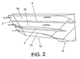
- the intake duct 1 has a substantially quadrangular cross section and comprises an internal straight portion 1a, an internal first bend portion 1b and an internal second bend portion 1c which extend between a duct air inlet 2 and a plenum entry 3 of a per se conventional auxiliary power unit (not shown in the drawings).
- the straight portion 1a connects with the first bend portion 1b that extends downwards and connects with the second bend portion 1c that bends leftwards.
- An upper acoustic guide vane 4 and a lower acoustic guide vane 5 are placed horizontally between the sidewalls of the straight portion 1a of the duct 1. As the first bend portion 1b of the intake duct 1 bends downwards, the upper acoustic guide vane 4 is slightly longer than the lower acoustic guide vane 5 and extends into the first bend portion 1b.
- the second bend portion 1c has a first side wall 8 with a first sidewall curvature a1 and a second side wall 9 with a second sidewall curvature a2.
- the second side wall 9 is shorter than the first side wall 8.
- Two curved aerodynamic guide vanes 6,7 are located in the second bend portion 1c proximate to the plenum inlet 3.
- the aerodynamic guide vanes 6,7 extend vertically between the top wall and the bottom wall of the second bend portion 1c.
- the first curved aerodynamic guide vane 6 is located in a radial position in the middle between the first side wall 8 and the second side wall 9, approximately in the middle of the second bend portion 1c, whilst the second curved aerodynamic guide vane 7 is located between the first aerodynamic guide vane 6 and the second side wall 9 of the second bend portion 1c.
- the second aerodynamic guide vane 7 is shorter than the first aerodynamic guide vane 6.
- Both aerodynamic guide vanes 6,7 have a shape that follows the curvature of the second bend portion.
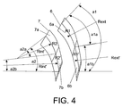
- the first aerodynamic guide vane 6 comprised a first curved section 6a and a second curved section 6b.
- the first curved section 6a of the first aerodynamic guide vane 6 is located in a radial position R1 in the middle between the first external radius Rext given by a first arched section a1a of the first side wall curvature a1, and a first internal radius Rint given by a first arched section a2a of the second side wall curvature a2 of the second bend portion 1c.
- the second curved section 6b of the curved first aerodynamic guide vane 6 is located in a radial position R1' in the middle between a second external radius Rext' given by a second arched section a1b of the first side wall curvature a1 and a second internal radius Rint' given by a second arched section a2b of the second side wall curvature a2.
- Figure 4 shows a possible relationship between the geometries of the curvatures of the second bend portion 1c and of the two aerodynamic guide vanes 6,7 in the embodiment of the intake duct shown in figure 1.
- the upper acoustic guide vane 4 and the lower acoustic guide vane 5 are positioned such that the straight portion 1a is horizontally divided into flow paths 2a,2b,2c.
- the longitudinal axes of the acoustic vanes 4,5 are slightly divergent in the direction of the free ends of the acoustic guide vanes 4,5 i.e. the flowpaths have a narrower cross section at the duct air inlet 2 than at the free ends of the acoustic guide vanes 4,5.
- the longitudinal axis of the upper acoustic guide vane 4 may deviate from the longitudinal axis of the top wall of the straight portion 1a of the intake duct by approx. 1.7°.
- the deviation between the longitudinal axis of the upper acoustic guide vane 4 and the longitudinal axis of the lower acoustic guide vane 5 may be approx. 2.6°.
- the deviation between the lower acoustic guide vane 5 and the longitudinal axis of the bottom wall of the straight portion 1a of the intake duct by approx. 2-7°.
Landscapes
- Engineering & Computer Science (AREA)
- Chemical & Material Sciences (AREA)
- Combustion & Propulsion (AREA)
- Mechanical Engineering (AREA)
- General Engineering & Computer Science (AREA)
- Aviation & Aerospace Engineering (AREA)
- Structures Of Non-Positive Displacement Pumps (AREA)
- Duct Arrangements (AREA)
- Current-Collector Devices For Electrically Propelled Vehicles (AREA)
- Other Liquid Machine Or Engine Such As Wave Power Use (AREA)
- Soundproofing, Sound Blocking, And Sound Damping (AREA)
Applications Claiming Priority (1)
| Application Number | Priority Date | Filing Date | Title |
|---|---|---|---|
| ES200403174A ES2273546B1 (es) | 2004-12-31 | 2004-12-31 | Conducto de admision para un grupo electrogeno auxiliar con aletas guiadoras aeroacusticas. |
Publications (3)
| Publication Number | Publication Date |
|---|---|
| EP1749993A2 true EP1749993A2 (fr) | 2007-02-07 |
| EP1749993A3 EP1749993A3 (fr) | 2011-01-05 |
| EP1749993B1 EP1749993B1 (fr) | 2012-03-28 |
Family
ID=36216803
Family Applications (1)
| Application Number | Title | Priority Date | Filing Date |
|---|---|---|---|
| EP05078054A Expired - Lifetime EP1749993B1 (fr) | 2004-12-31 | 2005-12-28 | Conduit d'entrée avec aubes de guidage air-acoustiquées pour une unité de puissance auxiliaire |
Country Status (6)
| Country | Link |
|---|---|
| US (1) | US7597283B2 (fr) |
| EP (1) | EP1749993B1 (fr) |
| BR (1) | BRPI0600695A (fr) |
| CA (1) | CA2531699C (fr) |
| EA (1) | EA009545B1 (fr) |
| ES (1) | ES2273546B1 (fr) |
Families Citing this family (12)
| Publication number | Priority date | Publication date | Assignee | Title |
|---|---|---|---|---|
| US9194293B2 (en) * | 2007-09-18 | 2015-11-24 | Hamilton Sundstrand Corporation | Air inlet noise attenuation assembly |
| KR100928595B1 (ko) * | 2007-12-28 | 2009-11-26 | 삼성중공업 주식회사 | 덕트의 배기구조 |
| US8322981B2 (en) * | 2009-03-02 | 2012-12-04 | Hamilton Sundstrand Corporation | Aircraft fluid diversion inlet louver |
| US8733694B2 (en) * | 2011-01-06 | 2014-05-27 | Jay M. Francisco | Arrangement for maintaining flow to an air inlet of an auxiliary power unit assembly |
| FR2975547B1 (fr) * | 2011-05-20 | 2013-06-07 | Turbomeca | Procede de rationalisation de chaine de composants electriques d'un aeronef, architecture de mise en oeuvre et aeronef correspondant |
| US9051057B2 (en) * | 2011-12-28 | 2015-06-09 | Embraer S.A. | Aircraft air inlet diverter assemblies with improved aerodynamic characteristics |
| US9719352B2 (en) | 2014-12-17 | 2017-08-01 | Honeywell International Inc. | Compartment based inlet particle separator system |
| US10087839B2 (en) * | 2016-02-24 | 2018-10-02 | Pratt & Whitney Canada Corp. | Air intake for turboprop engine |
| US10030581B2 (en) * | 2016-02-24 | 2018-07-24 | Pratt & Whitney Canada Corp. | Air intake with scroll portion and strutted portion for gas turbine engine |
| US11124310B2 (en) | 2018-04-10 | 2021-09-21 | DMS Aviation Services, LLC | Pressure recovery device for an aircraft engine air intake |
| US10266275B1 (en) | 2018-04-10 | 2019-04-23 | DMS Aviation Services, LLC | Pressure recovery device for an aircraft engine air intake |
| CN115384784B (zh) * | 2022-07-20 | 2025-08-08 | 中国航发哈尔滨东安发动机有限公司 | 一种适应复杂进气路线的高性能小体积进气转接装置 |
Family Cites Families (17)
| Publication number | Priority date | Publication date | Assignee | Title |
|---|---|---|---|---|
| US2272620A (en) * | 1939-02-20 | 1942-02-10 | Internat Multifeed Drills Ltd | Diamond drill |
| US2365328A (en) * | 1941-12-10 | 1944-12-19 | Goodrich Co B F | Protective shield |
| GB877838A (en) * | 1959-08-20 | 1961-09-20 | Rolls Royce | Improvements relating to gas turbine engine air intakes |
| US3374856A (en) * | 1966-09-09 | 1968-03-26 | Garrett Corp | Flexible sound attenuating duct with foamed plastic lining |
| US3583417A (en) * | 1969-10-07 | 1971-06-08 | Boeing Co | Sound suppressor for jet engine inlet |
| US3778983A (en) * | 1972-08-30 | 1973-12-18 | Avco Corp | Integral multichannel separator |
| US4058141A (en) * | 1975-08-20 | 1977-11-15 | The United States Of America As Represented By The Secretary Of The Air Force | Supersonic flow diffuser with energy redistribution |
| US4354346A (en) * | 1979-05-24 | 1982-10-19 | British Aerospace | Intake ducts for aircraft jet propulsion plant |
| US4685942A (en) * | 1982-12-27 | 1987-08-11 | General Electric Company | Axial flow inlet particle separator |
| US4787421A (en) * | 1986-04-14 | 1988-11-29 | General Motors Corporation | Flow path defining means and method of making |
| US5140819A (en) * | 1989-09-28 | 1992-08-25 | Sundstrand Corporation | Turbine inlet silencer |
| US5709529A (en) * | 1995-11-14 | 1998-01-20 | Westinghouse Electric Corporation | Optimization of turbomachinery harmonics |
| US5725180A (en) * | 1995-12-29 | 1998-03-10 | General Electric Company | Aircraft engine pitot plenum intake |
| US6050527A (en) * | 1997-12-19 | 2000-04-18 | The Boeing Company | Flow control device to eliminate cavity resonance |
| JP2000120497A (ja) * | 1998-10-19 | 2000-04-25 | Honda Motor Co Ltd | 自動車用吸気消音装置 |
| GB0206139D0 (en) * | 2002-03-15 | 2002-04-24 | Rolls Royce Plc | A variable position intake for an aircraft mounted gas turbine engine |
| DE10331085C5 (de) * | 2003-07-09 | 2008-02-28 | Rehau Ag + Co. | Luftführungselement für ein Kraftfahrzeug |
-
2004
- 2004-12-31 ES ES200403174A patent/ES2273546B1/es not_active Expired - Fee Related
-
2005
- 2005-12-28 EP EP05078054A patent/EP1749993B1/fr not_active Expired - Lifetime
- 2005-12-29 CA CA2531699A patent/CA2531699C/fr not_active Expired - Lifetime
- 2005-12-30 EA EA200501935A patent/EA009545B1/ru not_active IP Right Cessation
- 2005-12-30 US US11/324,020 patent/US7597283B2/en active Active
-
2006
- 2006-01-02 BR BRPI0600695-7A patent/BRPI0600695A/pt not_active IP Right Cessation
Also Published As
| Publication number | Publication date |
|---|---|
| CA2531699A1 (fr) | 2006-06-30 |
| EP1749993A3 (fr) | 2011-01-05 |
| EA009545B1 (ru) | 2008-02-28 |
| BRPI0600695A (pt) | 2006-09-19 |
| CA2531699C (fr) | 2012-11-13 |
| ES2273546A1 (es) | 2007-05-01 |
| EP1749993B1 (fr) | 2012-03-28 |
| ES2273546B1 (es) | 2008-03-16 |
| US20060179846A1 (en) | 2006-08-17 |
| US7597283B2 (en) | 2009-10-06 |
| EA200501935A3 (ru) | 2006-12-29 |
| EA200501935A2 (ru) | 2006-08-25 |
Similar Documents
| Publication | Publication Date | Title |
|---|---|---|
| EP1749993B1 (fr) | Conduit d'entrée avec aubes de guidage air-acoustiquées pour une unité de puissance auxiliaire | |
| EP1895140B1 (fr) | Buse d'échappement de Soufflante pour turboréacteur à double flux | |
| US6845606B2 (en) | Variable cycle propulsion system with gas tapping for a supersonic airplane, and a method of operation | |
| EP2098714B1 (fr) | Turboréacteur à double flux à taux de dilution élevé | |
| CA2609291C (fr) | Capot de reacteur a double flux et methode de fonctionnement | |
| US7861513B2 (en) | Aeroengine ventilation system | |
| CN103108805B (zh) | 优化飞机总能量效率的方法,和实施这种方法的主动力装置 | |
| JP4981624B2 (ja) | ターボファンエンジンノズル組立体及びターボファンエンジン組立体 | |
| KR101814842B1 (ko) | 터빈 엔진의 배기 라인 내에 설치된 열교환 구조체 | |
| US7886518B2 (en) | Turbofan engine cowl assembly and method of operating the same | |
| JP4890423B2 (ja) | ターボファンエンジンノズル組立体及びターボファンエンジン組立体 | |
| CN107893701A (zh) | 用于整流罩下分流冷却的方法和设备 | |
| JP2009510304A (ja) | プリクーラを備えたターボファン | |
| US20140290270A1 (en) | Attachment pylon for a turbine engine | |
| EP2514947A1 (fr) | Moteur à turbine à gaz avec ensemble formant nacelle comprenant une cavité et une structure de confinement de soufflante d'avion | |
| CN107848629A (zh) | 在机身后部上包括具有风扇的推进组件的飞机 | |
| EP4194679B1 (fr) | Éjecteur de cône de queue pour système de refroidissement de câble d'alimentation dans un moteur à turbine à gaz | |
| WO2005100765A1 (fr) | Turbopropulseur a deux entrees | |
| US6926232B2 (en) | Variable cycle propulsion system with compressed air tapping for a supersonic airplane | |
| EP4219314B1 (fr) | Système de propulsion à ventilateur à couche limite canalisée | |
| US20030113205A1 (en) | Air intake system of a propeller-turbine engine | |
| CN215333139U (zh) | 航空发动机进气道以及航空发动机 | |
| CN105217047A (zh) | 具有隔热罩的柔性排气通道 |
Legal Events
| Date | Code | Title | Description |
|---|---|---|---|
| PUAI | Public reference made under article 153(3) epc to a published international application that has entered the european phase |
Free format text: ORIGINAL CODE: 0009012 |
|
| AK | Designated contracting states |
Kind code of ref document: A2 Designated state(s): AT BE BG CH CY CZ DE DK EE ES FI FR GB GR HU IE IS IT LI LT LU LV MC NL PL PT RO SE SI SK TR |
|
| AX | Request for extension of the european patent |
Extension state: AL BA HR MK YU |
|
| RAP1 | Party data changed (applicant data changed or rights of an application transferred) |
Owner name: AIRBUS OPERATIONS S.L. |
|
| PUAL | Search report despatched |
Free format text: ORIGINAL CODE: 0009013 |
|
| AK | Designated contracting states |
Kind code of ref document: A3 Designated state(s): AT BE BG CH CY CZ DE DK EE ES FI FR GB GR HU IE IS IT LI LT LU LV MC NL PL PT RO SE SI SK TR |
|
| AX | Request for extension of the european patent |
Extension state: AL BA HR MK YU |
|
| RIC1 | Information provided on ipc code assigned before grant |
Ipc: F02C 7/04 20060101ALI20101202BHEP Ipc: B64D 33/02 20060101ALI20101202BHEP Ipc: F02C 7/045 20060101AFI20060504BHEP |
|
| 17P | Request for examination filed |
Effective date: 20110704 |
|
| AKX | Designation fees paid |
Designated state(s): DE FR GB IT |
|
| GRAP | Despatch of communication of intention to grant a patent |
Free format text: ORIGINAL CODE: EPIDOSNIGR1 |
|
| GRAS | Grant fee paid |
Free format text: ORIGINAL CODE: EPIDOSNIGR3 |
|
| GRAA | (expected) grant |
Free format text: ORIGINAL CODE: 0009210 |
|
| AK | Designated contracting states |
Kind code of ref document: B1 Designated state(s): DE FR GB IT |
|
| REG | Reference to a national code |
Ref country code: GB Ref legal event code: FG4D |
|
| REG | Reference to a national code |
Ref country code: DE Ref legal event code: R096 Ref document number: 602005033350 Country of ref document: DE Effective date: 20120531 |
|
| PLBE | No opposition filed within time limit |
Free format text: ORIGINAL CODE: 0009261 |
|
| STAA | Information on the status of an ep patent application or granted ep patent |
Free format text: STATUS: NO OPPOSITION FILED WITHIN TIME LIMIT |
|
| 26N | No opposition filed |
Effective date: 20130103 |
|
| REG | Reference to a national code |
Ref country code: DE Ref legal event code: R097 Ref document number: 602005033350 Country of ref document: DE Effective date: 20130103 |
|
| GBPC | Gb: european patent ceased through non-payment of renewal fee |
Effective date: 20121228 |
|
| REG | Reference to a national code |
Ref country code: FR Ref legal event code: ST Effective date: 20130830 |
|
| PG25 | Lapsed in a contracting state [announced via postgrant information from national office to epo] |
Ref country code: DE Free format text: LAPSE BECAUSE OF NON-PAYMENT OF DUE FEES Effective date: 20130702 |
|
| REG | Reference to a national code |
Ref country code: DE Ref legal event code: R119 Ref document number: 602005033350 Country of ref document: DE Effective date: 20130702 |
|
| PG25 | Lapsed in a contracting state [announced via postgrant information from national office to epo] |
Ref country code: FR Free format text: LAPSE BECAUSE OF NON-PAYMENT OF DUE FEES Effective date: 20130102 Ref country code: GB Free format text: LAPSE BECAUSE OF NON-PAYMENT OF DUE FEES Effective date: 20121228 |
|
| PGFP | Annual fee paid to national office [announced via postgrant information from national office to epo] |
Ref country code: IT Payment date: 20151228 Year of fee payment: 11 |
|
| PG25 | Lapsed in a contracting state [announced via postgrant information from national office to epo] |
Ref country code: IT Free format text: LAPSE BECAUSE OF NON-PAYMENT OF DUE FEES Effective date: 20161228 |