EP1749994A2 - Méthode et appareil pour ajouter un fluide secondaire dans la conduite de carburant d'une turbine à gaz - Google Patents
Méthode et appareil pour ajouter un fluide secondaire dans la conduite de carburant d'une turbine à gaz Download PDFInfo
- Publication number
- EP1749994A2 EP1749994A2 EP06118263A EP06118263A EP1749994A2 EP 1749994 A2 EP1749994 A2 EP 1749994A2 EP 06118263 A EP06118263 A EP 06118263A EP 06118263 A EP06118263 A EP 06118263A EP 1749994 A2 EP1749994 A2 EP 1749994A2
- Authority
- EP
- European Patent Office
- Prior art keywords
- fuel line
- fuel
- line
- spool
- passageway
- Prior art date
- Legal status (The legal status is an assumption and is not a legal conclusion. Google has not performed a legal analysis and makes no representation as to the accuracy of the status listed.)
- Withdrawn
Links
Images

Classifications
-
- F—MECHANICAL ENGINEERING; LIGHTING; HEATING; WEAPONS; BLASTING
- F02—COMBUSTION ENGINES; HOT-GAS OR COMBUSTION-PRODUCT ENGINE PLANTS
- F02C—GAS-TURBINE PLANTS; AIR INTAKES FOR JET-PROPULSION PLANTS; CONTROLLING FUEL SUPPLY IN AIR-BREATHING JET-PROPULSION PLANTS
- F02C7/00—Features, components parts, details or accessories, not provided for in, or of interest apart form groups F02C1/00 - F02C6/00; Air intakes for jet-propulsion plants
- F02C7/22—Fuel supply systems
-
- F—MECHANICAL ENGINEERING; LIGHTING; HEATING; WEAPONS; BLASTING
- F02—COMBUSTION ENGINES; HOT-GAS OR COMBUSTION-PRODUCT ENGINE PLANTS
- F02C—GAS-TURBINE PLANTS; AIR INTAKES FOR JET-PROPULSION PLANTS; CONTROLLING FUEL SUPPLY IN AIR-BREATHING JET-PROPULSION PLANTS
- F02C7/00—Features, components parts, details or accessories, not provided for in, or of interest apart form groups F02C1/00 - F02C6/00; Air intakes for jet-propulsion plants
- F02C7/22—Fuel supply systems
- F02C7/232—Fuel valves; Draining valves or systems
-
- F—MECHANICAL ENGINEERING; LIGHTING; HEATING; WEAPONS; BLASTING
- F02—COMBUSTION ENGINES; HOT-GAS OR COMBUSTION-PRODUCT ENGINE PLANTS
- F02C—GAS-TURBINE PLANTS; AIR INTAKES FOR JET-PROPULSION PLANTS; CONTROLLING FUEL SUPPLY IN AIR-BREATHING JET-PROPULSION PLANTS
- F02C9/00—Controlling gas-turbine plants; Controlling fuel supply in air- breathing jet-propulsion plants
- F02C9/26—Control of fuel supply
-
- F—MECHANICAL ENGINEERING; LIGHTING; HEATING; WEAPONS; BLASTING
- F05—INDEXING SCHEMES RELATING TO ENGINES OR PUMPS IN VARIOUS SUBCLASSES OF CLASSES F01-F04
- F05D—INDEXING SCHEME FOR ASPECTS RELATING TO NON-POSITIVE-DISPLACEMENT MACHINES OR ENGINES, GAS-TURBINES OR JET-PROPULSION PLANTS
- F05D2270/00—Control
- F05D2270/30—Control parameters, e.g. input parameters
- F05D2270/301—Pressure
Definitions
- the present invention is directed toward a method and apparatus for adding a flow of secondary fluid to a fuel line in a gas turbine engine providing control pressure to a controlled system, and more specifically, toward a method and apparatus for adding a secondary fluid, which may comprise for example, washed and heated fuel, to a control pressure fuel line downstream of a pressurizing valve in a manner that substantially prevents unintended mixing of the secondary fluid and a burn fuel flow to the gas turbine engine.
- a secondary fluid which may comprise for example, washed and heated fuel
- Gas turbine engines such as those used in aircraft, include various valves and mechanisms for providing a controlled flow of fuel to a combustion chamber. It is also known in such engines to use fuel pressures and pressure differences to drive various actuators and other devices. This "muscle" pressure is often generated in a fuel line separate from a main burn fuel line which may sometimes be referred to as a control fuel line.
- Gas turbine engines include a variety of filters for filtering fuel in different passageways. Burn fuel need not be as clean as the fuel that is used for various engine controls. It is therefore known to provide additional filtering for fuel that will be used in a control fuel line. If the control fuel is to be used in locations where freezing might be a problem, it is also known to provide a heated control fuel supply. Such filtered and heated fuel may be referred to as washed heated fuel.
- Fuel supplied to a combustion chamber must be accurately metered to control the power developed by an engine.
- Many gas turbine engines use a metering valve to accurately meter a fuel supply and a pressurizing valve for increasing the metered fuel supply to a given pressure.
- the pressurizing valve generally exhibits what may be referred to as "drip tight" shutoff. In other words, closing the pressurizing valve substantially completely stops the flow of fuel therethrough. This may be contrasted with valves that use matched clearances to restrict fuel flow therepast but which are known and intended to leak at least a small amount.
- a first aspect of which comprises a gas turbine engine fuel system that includes a fuel line and a pressurizing valve in the fuel line having a burn fuel outlet to a burn fuel line providing burn fuel to the engine and a control fuel outlet to a control fuel line providing pressure for controlling an engine system.
- the pressurizing valve is shiftable between a closed position blocking fuel flow to the burn fuel line and to the control fuel line and a second position.
- a secondary flow valve is provided that has a first end in fluid communication with the burn fuel line downstream of the pressurizing valve and a second end in fluid communication with the control fuel line downstream of the pressurizing valve.
- the secondary flow valve controls the addition of a secondary fluid from a secondary fluid line to the control fuel line and substantially prevents the secondary fluid from reaching the secondary flow valve first end.
- Another aspect of the invention comprises, in a gas turbine engine fuel system that includes a pressurizing valve providing burn fuel to a burn fuel line at a first pressure and control fuel to a control fuel line at a second pressure, a method of adding a secondary fluid to the control fuel line downstream of the pressurizing valve.
- the method involves providing a first passageway connecting the burn fuel line to the control fuel line and providing a second passageway connecting a secondary fluid line to the first passageway.
- a movable spool is provided in the first passageway for substantially blocking the first passageway and selectively blocking the second passageway. The spool is moved from a first position blocking the first passageway and the second passageway to a second position blocking the first passageway and allowing communication between the second passageway and the control fuel line.
- a further aspect of the invention comprises, in a gas turbine engine fuel system including a pressurizing valve providing burn fuel to a burn fuel line at a first pressure and control fuel to a control fuel line at a second pressure, a method that involves providing a washed, heated fuel flow to the control fuel line downstream of the pressurizing valve and substantially preventing the washed heated fuel flow from mixing with the burn fuel before mixing with the control fuel.
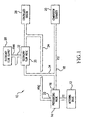
- Figure 1 is a block diagram schematically illustrating a system according to an embodiment of the present invention
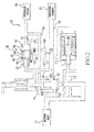
- Figure 2 illustrates, somewhat schematically, an embodiment of the present invention using a first type of secondary flow valve
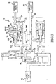
- FIG. 3 illustrates, somewhat schematically, an embodiment of the present invention using a different type of secondary flow valve
- Figure 4 is a flow chart illustrating a method according to an embodiment of the present invention.
- Figure 1 shows a fuel system 10 that includes a metering valve 12 providing a metered supply of fuel to a pressurizing valve 14 at a pressure P2.
- Pressurizing valve 14 has a first outlet 16 to burn fuel line 18 which provides a burn fuel flow to combustion chamber 20 at a pressure P22.
- Pressurizing valve 14 has a second outlet 22 to a control fuel line 24 and provides fuel at a pressure PFNC to a controlled system 26 through control fuel line 24.
- a secondary fluid such as washed and heated fuel, is supplied from secondary fuel supply 28 to secondary flow valve 30 through a secondary fluid line 32 at a pressure P1WH.
- Secondary flow valve 30 controllably adds this secondary fluid to control fuel line 24.
- Secondary flow valve 30 is also in fluid communication with burn fuel line 18 via passage 34, and the pressure in the burn fuel line 18 affects the position of secondary flow valve 30.
- Valve 30 comprises a spool 40 mounted for sliding movement in a chamber 42 which connects passage 34 to control fuel line 24.
- Spool 40 comprises a first end 44 and a second end 46 and first and second annular grooves 48 each containing a seal 50 such as an O-ring.
- a spring 52 biases spool 40 in the direction of arrow 54 - to the right in Figure 2.
- Seals 50 substantially prevent fluid from passage 34 from traveling past spool 40 in the direction of arrow 54 and substantially prevent fluid adjacent second end 46 of spool 40 from reaching first end 44 of spool 40.
- Secondary fuel line 32 enters chamber 42 through an opening 56 that is blocked and exposed by the movement of spool 40.
- pressurizing valve 14 opens and fluid begins to flow through second outlet 22 into control fuel line 24.
- fuel also begins to flow through first outlet 16 into burn fuel line 18.
- Pressure PFNC in control fuel line 24 is greater than pressure P22 in burn fuel line 18 and therefore holds spool 40 in the position shown in Figure 2 with spring 52 compressed. In this position, spool 40 uncovers opening 56 and allows fluid in secondary fluid line 32, which is at a higher pressure than pressure PFNC, to enter chamber 42 and mix with fuel in the control fuel line 24. Seals 50 prevent the fluid from secondary fuel line 32 from reaching the first end 44 of spool 40 and mixing with the fuel in passageway 34.
- pressurizing valve 14 When pressurizing valve 14 is closed, no further fluid flows through first and second outlets 16 and 22 and the pressures in burn fuel line 18 and control fuel line 24 begin to drop. When the pressures drop below a given level, the biasing force exerted by spring 52 forces spool 40 in the direction of arrow 54 and covers opening 56 to stop further fluid flow from secondary fuel line 32 through opening 56. In this manner, drip-tight shutoff of the secondary fuel flow is provided. The opening of pressurizing valve 14 returns spool 40 to the position illustrated in Figure 2.
- valve 30 comprises a spool 60 mounted for sliding movement in chamber 42 which connects passage 34 to control fuel line 24.
- Spool 60 comprises a first end 64 and a second end 66 and three annular sealing grooves 68 each containing a seal 70 such as an O-ring.
- a spring 72 biases spool 60 in the direction of arrow 54 - to the right in Figure 3.
- Spool 60 includes an annular flow groove 74 between a pair of annular sealing grooves 68 that communicates with a central passage 76 which includes a filter 78 and a bleed 80.
- Figure 4 illustrates a method of adding a secondary fluid to a control fuel line in a gas turbine engine fuel system that involves providing a first passageway connecting the burn fuel line to the control fuel line at a step 100, providing a second passageway connecting a secondary fluid line to the first passageway at a step 102, providing a movable spool in the first passageway for substantially blocking the first passageway and selectively blocking the second passageway at a step 104 and moving the spool from a first position blocking the first passageway and the second passageway to a second position backing the first passageway and allowing communication between the second passageway and the control fuel line at a step 106.
Landscapes
- Engineering & Computer Science (AREA)
- Chemical & Material Sciences (AREA)
- Combustion & Propulsion (AREA)
- Mechanical Engineering (AREA)
- General Engineering & Computer Science (AREA)
- Feeding And Controlling Fuel (AREA)
- Output Control And Ontrol Of Special Type Engine (AREA)
Applications Claiming Priority (1)
| Application Number | Priority Date | Filing Date | Title |
|---|---|---|---|
| US11/193,334 US20060053796A1 (en) | 2004-09-10 | 2005-08-01 | Method and apparatus for adding a secondary fluid flow to a gas turbine engine control fuel line |
Publications (2)
| Publication Number | Publication Date |
|---|---|
| EP1749994A2 true EP1749994A2 (fr) | 2007-02-07 |
| EP1749994A3 EP1749994A3 (fr) | 2008-05-21 |
Family
ID=37396048
Family Applications (1)
| Application Number | Title | Priority Date | Filing Date |
|---|---|---|---|
| EP06118263A Withdrawn EP1749994A3 (fr) | 2005-08-01 | 2006-08-01 | Méthode et appareil pour ajouter un fluide secondaire dans la conduite de carburant d'une turbine à gaz |
Country Status (2)
| Country | Link |
|---|---|
| US (1) | US20060053796A1 (fr) |
| EP (1) | EP1749994A3 (fr) |
Families Citing this family (1)
| Publication number | Priority date | Publication date | Assignee | Title |
|---|---|---|---|---|
| US7966995B2 (en) * | 2007-09-05 | 2011-06-28 | Honeywell International Inc. | Dual level pressurization control based on fuel flow to one or more gas turbine engine secondary fuel loads |
Family Cites Families (7)
| Publication number | Priority date | Publication date | Assignee | Title |
|---|---|---|---|---|
| GB2180005B (en) * | 1985-09-04 | 1989-03-01 | Rolls Royce | Fuel systems for gas turbine engines |
| GB8530847D0 (en) * | 1985-12-14 | 1986-01-22 | Lucas Ind Plc | Gas turbine engine fuel control system |
| US5715674A (en) * | 1995-12-22 | 1998-02-10 | United Technologies Corporation | Hydromechanical control for a variable delivery, positive displacement fuel pump |
| ES2193606T3 (es) * | 1997-12-12 | 2003-11-01 | Allied Signal Inc | Valvula de derivacion proporcional y de fuerzas equilibradas. |
| GB9727157D0 (en) * | 1997-12-24 | 1998-02-25 | Lucas Ind Plc | Fuel system for a gas turbine engine |
| FR2806488B1 (fr) * | 2000-03-16 | 2002-05-17 | Snecma Moteurs | Dispositif et procede de regulation de pression et debit de carburant d'alimentation d'une unite de servovannes |
| US6401446B1 (en) * | 2000-06-23 | 2002-06-11 | Hamilton Sundstrand Corporation | Valve apparatus for providing shutoff and overspeed protection in a gas turbine fuel system |
-
2005
- 2005-08-01 US US11/193,334 patent/US20060053796A1/en not_active Abandoned
-
2006
- 2006-08-01 EP EP06118263A patent/EP1749994A3/fr not_active Withdrawn
Also Published As
| Publication number | Publication date |
|---|---|
| EP1749994A3 (fr) | 2008-05-21 |
| US20060053796A1 (en) | 2006-03-16 |
Similar Documents
| Publication | Publication Date | Title |
|---|---|---|
| CA2756846C (fr) | Robinet de sectionnement a detection de debit | |
| EP2497923B1 (fr) | Système de carburant | |
| US6195978B1 (en) | Ecology system for a gas turbine engine | |
| GB2512170B (en) | A fuel circuit of a turbine engine | |
| US8366404B2 (en) | Fuel system | |
| US20100213010A1 (en) | Automatic Shut-Off Valve For The Oil Circuit In An Airplane Engine | |
| EP2813682B1 (fr) | Soupape de dosage de combustible à faible frottement | |
| CA2706211C (fr) | Dispositif de filtration d'air pour systeme pneumatique de turbine a gaz | |
| EP4015814B1 (fr) | Ensemble filtre à carburant | |
| US12128336B2 (en) | Fuel filter assembly | |
| CN101297108A (zh) | 适合于低粘性燃油的燃油喷射系统 | |
| US7587900B2 (en) | Gas turbine engine fuel control system having a transfer valve and a shutoff valve and a common controller therefor | |
| DE102016004997A1 (de) | Gasdurchflussbegrenzer für ein Kraftstoffsystem und Verfahren zu dessen Verwendung | |
| EP1749994A2 (fr) | Méthode et appareil pour ajouter un fluide secondaire dans la conduite de carburant d'une turbine à gaz | |
| EP1338774A1 (fr) | Système d'injection de carburant pour un moteur à combustion | |
| US7296406B2 (en) | System for positioning a piston including a fail fixed valve for holding the piston in position during a power interruption and method of using same | |
| CN107288787B (zh) | 燃油喷射系统 | |
| CN102884276B (zh) | 具有防热禁闭机构的喷射或其他系统及相关方法 | |
| EP3390786A1 (fr) | Dispositif de distribution d'écoulement entre une pompe à huile et un moteur | |
| DE102014211287A1 (de) | Fluid-Einspritzvorrichtung für eine Verbrennungskraftmaschine | |
| DE2921088A1 (de) | Kombiniertes druck- und durchfluss-regelventil |
Legal Events
| Date | Code | Title | Description |
|---|---|---|---|
| PUAI | Public reference made under article 153(3) epc to a published international application that has entered the european phase |
Free format text: ORIGINAL CODE: 0009012 |
|
| AK | Designated contracting states |
Kind code of ref document: A2 Designated state(s): AT BE BG CH CY CZ DE DK EE ES FI FR GB GR HU IE IS IT LI LT LU LV MC NL PL PT RO SE SI SK TR |
|
| AX | Request for extension of the european patent |
Extension state: AL BA HR MK YU |
|
| PUAL | Search report despatched |
Free format text: ORIGINAL CODE: 0009013 |
|
| AK | Designated contracting states |
Kind code of ref document: A3 Designated state(s): AT BE BG CH CY CZ DE DK EE ES FI FR GB GR HU IE IS IT LI LT LU LV MC NL PL PT RO SE SI SK TR |
|
| AX | Request for extension of the european patent |
Extension state: AL BA HR MK RS |
|
| RIC1 | Information provided on ipc code assigned before grant |
Ipc: F02C 9/26 20060101ALI20080415BHEP Ipc: F02C 7/232 20060101ALI20080415BHEP Ipc: F02C 7/22 20060101AFI20061120BHEP |
|
| AKX | Designation fees paid | ||
| REG | Reference to a national code |
Ref country code: DE Ref legal event code: 8566 |
|
| STAA | Information on the status of an ep patent application or granted ep patent |
Free format text: STATUS: THE APPLICATION IS DEEMED TO BE WITHDRAWN |
|
| 18D | Application deemed to be withdrawn |
Effective date: 20081122 |