EP1750003A2 - Dispositif permettant la supression d'infra-rouges - Google Patents
Dispositif permettant la supression d'infra-rouges Download PDFInfo
- Publication number
- EP1750003A2 EP1750003A2 EP06254000A EP06254000A EP1750003A2 EP 1750003 A2 EP1750003 A2 EP 1750003A2 EP 06254000 A EP06254000 A EP 06254000A EP 06254000 A EP06254000 A EP 06254000A EP 1750003 A2 EP1750003 A2 EP 1750003A2
- Authority
- EP
- European Patent Office
- Prior art keywords
- baffle
- duct
- stage
- engine
- infrared
- Prior art date
- Legal status (The legal status is an assumption and is not a legal conclusion. Google has not performed a legal analysis and makes no representation as to the accuracy of the status listed.)
- Granted
Links
- 230000005855 radiation Effects 0.000 claims abstract description 15
- 230000000903 blocking effect Effects 0.000 claims description 6
- 238000005086 pumping Methods 0.000 claims description 5
- 239000003570 air Substances 0.000 description 92
- 239000007789 gas Substances 0.000 description 42
- 230000001629 suppression Effects 0.000 description 23
- 238000001816 cooling Methods 0.000 description 12
- 238000000034 method Methods 0.000 description 10
- 230000009467 reduction Effects 0.000 description 9
- 230000033001 locomotion Effects 0.000 description 8
- 238000000576 coating method Methods 0.000 description 7
- 239000012080 ambient air Substances 0.000 description 6
- 239000011800 void material Substances 0.000 description 6
- 229910052751 metal Inorganic materials 0.000 description 5
- 239000002184 metal Substances 0.000 description 5
- 238000010790 dilution Methods 0.000 description 4
- 239000012895 dilution Substances 0.000 description 4
- 230000009471 action Effects 0.000 description 3
- 239000011248 coating agent Substances 0.000 description 3
- 238000010276 construction Methods 0.000 description 3
- 125000006850 spacer group Chemical group 0.000 description 3
- 230000003068 static effect Effects 0.000 description 3
- 230000000712 assembly Effects 0.000 description 2
- 238000000429 assembly Methods 0.000 description 2
- 230000008859 change Effects 0.000 description 2
- 238000001514 detection method Methods 0.000 description 2
- 238000012546 transfer Methods 0.000 description 2
- 238000013519 translation Methods 0.000 description 2
- 238000011144 upstream manufacturing Methods 0.000 description 2
- 229910000831 Steel Inorganic materials 0.000 description 1
- RTAQQCXQSZGOHL-UHFFFAOYSA-N Titanium Chemical compound [Ti] RTAQQCXQSZGOHL-UHFFFAOYSA-N 0.000 description 1
- 230000004888 barrier function Effects 0.000 description 1
- 238000005452 bending Methods 0.000 description 1
- 230000008901 benefit Effects 0.000 description 1
- 230000001419 dependent effect Effects 0.000 description 1
- 238000011161 development Methods 0.000 description 1
- 230000018109 developmental process Effects 0.000 description 1
- 230000009977 dual effect Effects 0.000 description 1
- 238000005516 engineering process Methods 0.000 description 1
- 239000012530 fluid Substances 0.000 description 1
- 238000010438 heat treatment Methods 0.000 description 1
- 239000003973 paint Substances 0.000 description 1
- 239000000243 solution Substances 0.000 description 1
- 239000007921 spray Substances 0.000 description 1
- 239000010959 steel Substances 0.000 description 1
- 239000010936 titanium Substances 0.000 description 1
- 229910052719 titanium Inorganic materials 0.000 description 1
- 230000007704 transition Effects 0.000 description 1
- 238000005406 washing Methods 0.000 description 1
- 239000013585 weight reducing agent Substances 0.000 description 1
Images








Classifications
-
- F—MECHANICAL ENGINEERING; LIGHTING; HEATING; WEAPONS; BLASTING
- F02—COMBUSTION ENGINES; HOT-GAS OR COMBUSTION-PRODUCT ENGINE PLANTS
- F02K—JET-PROPULSION PLANTS
- F02K1/00—Plants characterised by the form or arrangement of the jet pipe or nozzle; Jet pipes or nozzles peculiar thereto
- F02K1/78—Other construction of jet pipes
- F02K1/82—Jet pipe walls, e.g. liners
- F02K1/822—Heat insulating structures or liners, cooling arrangements, e.g. post combustion liners; Infrared radiation suppressors
- F02K1/825—Infrared radiation suppressors
-
- F—MECHANICAL ENGINEERING; LIGHTING; HEATING; WEAPONS; BLASTING
- F02—COMBUSTION ENGINES; HOT-GAS OR COMBUSTION-PRODUCT ENGINE PLANTS
- F02K—JET-PROPULSION PLANTS
- F02K1/00—Plants characterised by the form or arrangement of the jet pipe or nozzle; Jet pipes or nozzles peculiar thereto
- F02K1/38—Introducing air inside the jet
- F02K1/386—Introducing air inside the jet mixing devices in the jet pipe, e.g. for mixing primary and secondary flow
Definitions
- This invention relates generally to infrared suppression devices and more generally to methods and apparatus for reducing infrared emission from gas turbines such as those used, for example, in helicopters.
- Some aspects of the present invention therefore provide a method for suppressing infrared radiation from an engine of an aircraft operating in an environment.
- the method includes directing hot exhaust from the aircraft engine into a lobed mixer of a single baffle infrared suppressor having a collapsible, translatable baffle to generate alternating flows of hot exhaust gas and cold air.
- the method further includes directing the alternating flows of hot exhaust gas and cold air towards the single baffle assembly to mix the hot exhaust gas with the cold air.
- the method includes directing hot exhaust from the aircraft engine into a lobed mixer of a single baffle infrared suppressor to generate alternating flows of hot exhaust gas and cold air.
- the method further includes directing the alternating flows of hot exhaust gas and cold air towards the single baffle assembly to mix the hot exhaust gas with the cold air, and positioning a hood and a panel of the infrared suppressor in accordance with the threat environment.
- Still other aspects of the present invention provide a method for suppressing infrared radiation from an engine of an aircraft operating in an environment.
- the method includes directing hot exhaust from the aircraft engine into a lobed mixer of a single baffle infrared suppressor to generate alternating flows of hot exhaust gas and cold air.
- the method further includes directing the alternating flows of hot exhaust gas and cold air towards the single baffle assembly to mix the hot exhaust gas with the cold air, and selecting a mode of operation from a set of modes.
- the set of modes includes a first mode in which a direct view of an exhaust cavity is blocked, a second mode that pumps and blocks a line-of-sight into the engine, and a third mode in which backpressure is minimized or reduced.
- inventions for suppressing infrared radiation from an engine of an aircraft operating in an environment.
- the infrared suppressor is configured to direct hot exhaust from the aircraft engine into a lobed mixer of a single baffle assembly having a collapsible, translatable baffle to generate alternating flows of hot exhaust gas and cold air.
- the suppressor is further configured to direct the alternating flows of hot exhaust gas and cold air towards the single baffle assembly to mix the hot exhaust gas with the cold air.
- an infrared suppressor for suppressing infrared radiation from an engine of an aircraft operating in an environment.
- the suppressor is configured to direct hot exhaust from the aircraft engine into a lobed mixer of a single baffle assembly having a collapsible, translatable baffle to generate alternating flows of hot exhaust gas and cold air.
- the suppressor is further configured to direct the alternating flows of hot exhaust gas and cold air towards the single baffle assembly to mix the hot exhaust gas with the cold air.
- the infrared suppressor also comprises a hood and a panel that are repositionable in accordance with the threat environment.
- the set of modes includes a first mode in which direct view of an exhaust cavity is blocked and which facilitates high infrared suppression when the aircraft is under threat, a second mode which blocks a line-of-sight into the engine and which represents a compromise between suppression and performance for some protection in hostile environments, and a third mode in which backpressure is minimized or reduced which facilitates high performance for emergency situations or benign environments.
- the infrared suppressor includes a stage I duct, a stage II duct, and a stage III duct.
- the stage I duct has an adapter ring configured to slide over a tailpipe of the engine and a lobed mixer.
- the stage II duct is coupled to the stage I duct and has a collapsible and translatable single baffle assembly.
- the stage II duct is configured to receive exhaust from the engine that leaves the stage I duct.
- the stage III duct is coupled to the stage II duct and configured to receive exhaust from the engine that leaves said stage II duct.
- the stage III duct includes a hood and a panel that are positionable and/or rotatable to turn exhaust leaving the stage III duct.
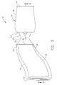
- an infrared suppressor assembly 10 is fitted to the back end of a standard turboshaft or turboprop engine (not shown).
- An adapter ring 12 slides over the tailpipe of the turboshaft engine.
- Adapter ring 12 may comprise a finger seal having a plurality of metal strips (not shown) that fit over a cylindrical section of an engine and hold tight to it. The metal strips are mounted on a slidable and moveable disk, so that if the engine moves relative to suppressor assembly 10, adapter ring 12 takes up the movement.
- Hot exhaust gas from the jet engine thereby flows into a stage I duct 14 that transitions from a round shape to a rectangular shape in the natural direction of the exhaust flow.
- stage I duct 14 is straight, however, in other configurations, stage I duct 14 can be repositioned to facilitate guiding the exhaust flows from the engine and away from the aircraft.
- FIG 2 is a side elevation view of infrared suppressor assembly 10 of Figure 1.
- a stage II duct 16 having a rectangular opening 18 and wall 37 receives exhaust from the jet engine that leaves stage I duct 14.
- Stage II duct 16 exhausts into a Stage III duct 20 that includes wall 39 and, among other things, physical barriers that prevent infrared sensors from looking up into infrared suppressor assembly 10 and using infrared sensors to observe hot parts of the jet engine (not shown in Figure 2 but described in conjunction with other figures below).
- Stage I duct 14 fits into stage II duct 16 which, in turn, fits into stage III duct 20.
- Figure 3 is an upright, vertical section view in elevation through the middle of assembly 10 shown in Figures 1 and 2.
- Hot engine air flow enters at adapter ring 12 and flows to the right as indicated by arrow A towards a plurality of spaced-apart lobes 22, only two of which are shown in Figure 3.
- Stage I duct 14 is also referred to herein as a "lobed mixer," for reasons that will become evident below.
- infrared suppression assembly 10 creates an induced flow resulting from entrainment with static air in that a high speed air flow A draws additional air into assembly 10.
- the additional air is, advantageously, cold (as compared to engine exhaust) ambient air.
- infrared suppression assembly 10 acts, in part, as an ejector-type nozzle.
- the mass flow within assembly 10 may be increased by about 150% (total) in some configurations by this entrainment of ambient air, which enters via an opening 24 formed around the rectangular exit end of stage I duct 14 by the larger rectangular input end 18 of Stage II duct 16.
- Air inlets 30 of lobes 22 open into opening 24 through stage I wall 56.
- Each stage can be mechanically coupled to the succeeding stage using, for example and without limitation, standoff posts or sheet metal wiggle strips.
- Lobes 22 are spaced from one another in two rows. Lobes 22 are spaced in two horizontal rows perpendicular to the plane of Figure 3, wherein the two rows are vertically separate from one another, as shown in Figure 3. Therefore, lobes 22 only partially impede high speed flow A.
- a single forward (or "hot") baffle 26 is provided in hot high speed air flow A behind lobes 22. Wedge-shaped forward baffle 26 splits flow A into two approximately equal flows B and C and also serves to hide lobes 22 from a line-of-sight from an exit of stage III duct 20.
- stage II duct 16 As the hot, high pressure exhaust flow races through stage II duct 16 it draws ambient, cool, outside air through opening 24.
- the cold air drawn through opening 24 passes alongside columns of hot air, thereby cooling an exiting gas stream flowing up and over baffle 42, from which the exiting gas stream flows into stage III duct 20, which acts as another ejector nozzle that pulls in more cold air into voids denoted by 34 and 90 and into opening 33, all of which are open to the atmosphere.
- Forward baffle 26 splits the hot, high pressure exhaust flow into two paths B and C.
- Forward baffle 26, which is substantially "V" shaped may include, in some configurations, a strut or other supporting structure 32.
- Forward or hot baffle 26 and cold baffle 42 together comprise a single baffle assembly, distinguishing it from previous designs that utilize a plurality of baffle assemblies.
- Cold baffle 42 is used to shield forward or hot baffle 26 as seen from an exit direction (i.e., looking into the exhaust exit of stage III duct 20).
- a "single baffle assembly” is defined as a combination of a single hot baffle and a single cold baffle.
- Lobes 22 may also be present in a single baffle assembly, as may shields 38, further described below.
- an assembly having a plurality of forward or hot baffles, a plurality of cold baffles, or a plurality of both is excluded from the term "single baffle assembly,” and rather is referred to herein as a “plural baffle assembly.”
- a “single baffle infrared suppressor,” such as infrared suppressor assembly 10 is referred to herein as a “single baffle infrared suppressor” configuration when it includes exactly one single baffle assembly and no plural baffle assemblies.
- a cold air flow is guided into a recess or void 90 inside cold baffle 42, drawn from inlets 33. This air is drawn around into the top and bottom surfaces of cold baffle 42 (as shown in Figure 3) and further guided by shields 38. Additional air is brought in at both sides of cold baffle 42, i.e., above and below the plane of Figure 3. This additional air is brought in towards the plane of Figure 3.
- Shields 38 which block the view of cold baffle 42 from the exhaust side, can be mounted to cold baffle 42 by a plurality of pins (not shown in the Figures), such as steel pegs, screws, bolts, standoffs, or rivets. These pins can be thermally conductive, to provide additional cooling of the surfaces of shields 38 and/or cold baffle 42. Other portions of the apparatus can be assembled using such pins as well.
- Line of sight shields can be provided to prevent a viewer looking upstream from exhaust end 35 from seeing hot parts of stage I duct 14. For example, mixer lobes 22 would normally be running hot because there is hot gas flowing underneath it. Line of sight shields can be added to prevent an observer from viewing lobes 22 looking into exhaust end 35.
- Figure 4 is a top view of suppressor assembly 10.
- Adapter ring 12 is shown at the left, stage II duct 16 at the center, and stage III duct 20 at right.
- Figure 5 is a centerline horizontal section through assembly 10, looking at the bottom half of the assembly with the top half removed. (Note that the centerline through Figure 1, which illustrates a turned configuration of stage I duct 14, is not straight. In configurations in which stage I duct 14 is not turned, the centerline would be straight.)
- Figure 6 is a partial cut-away perspective view of stage II duct 16 including the mixer section of stage I duct 14, and Figure 7 is a view looking into the mouth of stage II duct 16, in the direction of exhaust gas flow.
- the incoming high pressure hot air flow is broken into a plurality of flows F (only a few of which are shown in the Figures, and those shown in Figure 6 and Figure 7 are not necessarily corresponding flows F) that flow between and past lobes 22.
- Figures 6 and 7 are provided for orientation purposes.
- Figure 6 is a sectional perspective view that is cut-away directly upstream of lobes 22 in stage II duct 16.
- Wall 56 is of stage I duct 14, and mixer section, is shown inside stage II duct 16.
- Figure 8 is a perspective centerline section in elevation through line 8--8 of Figure 7. This section slices through two lobes 22, one above a horizontal centerline of stage II duct 16 and one below and shown at the right of the upper and lower lobe groupings. Since the bottom section of stage II duct 16 is a mirror image of the top section, the discussion here will be confined to the top section. The right-most upper lobes 22 shown in Figure 8, is shown cut in half. Another section along line 9--9 shown in Figure 7 goes through two lobes 22. This section is illustrated in Figure 9.
- Ends 58 of lobes 22 are open to thereby exhaust the cold air drawn into lobes 22 into a duct between forward baffle 26 and outer wall 54 of stage II duct 16. While in lobes 22, the cold air is next to the hot exhaust stream, separated from it by lobe side walls 52.
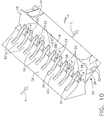
- FIG. 10 is a perspective view of a portion of stage II duct 16 looking down at inlets 30 with outer wall 54 of stage II duct 16 removed. Forward baffle 26 is also shown.
- Lobes 22 draw cold air from gap 24 through wall 56.
- hot air flows F emerge to strike hot baffle 26, they are surrounded on two sides by cold air coming from lobe ends 58 and on the top (in the visible portion seen in Figure 10) by cold air guided by segments 62 of wall 56, so that hot air flows F are surrounded on three sides by cold air.
- Stage I duct 14 can be referred to as a "lobed mixer,” because of the presence of lobes 22 and the mixing of cold ambient air in lobes 22 with the hot exhaust between lobes 22.
- hot exhaust gasses from an aircraft engine are directed into the lobed mixer of single baffle infrared suppressor 10, which includes a single baffle assembly comprising forward or hot baffle 26, cold baffle 42, and shields 38.
- the direction of hot exhaust from the engine in conjunction with cold air entering through gap 24 generates alternating flows of hot exhaust gas and cold air. These alternating flows are directed towards the single baffle assembly to mix the hot exhaust gas with the cold air to cool the emission from the engine to thereby reduce infrared emissions.
- the practical use of a single element baffle assembly in a single baffle infrared suppressor 10 is made possible by, among other things, the use of a lobed mixer.
- This mixer rapidly and effectively mixes engine bay cooling air in the engine exhaust with cold air to reduce or eliminate hot streaks, which are portions of unmixed engine exhaust air.
- hot streaks are a strong plume signature contributor, a source of radiation heat transfer to stage II duct walls, and where it persists further into suppressor 10, a source of hot streaks in stage II or stage III walls. Hot streaks cause the exhaust plume to become a significant contributor to an IR signature at close range.
- an additional flow path of cold air guided in part by segments 62 between lobe inlets 30 is provided so that the hot exhaust flows are surrounded on three sides by cold air.
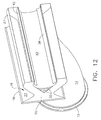
- Figure 12 is similar to Figure 11 but also shows a side wall 70 having a flow guide 32 as shown in Figure 5.
- Flow guide 32 scoops in cold ambient air that is in front of the flow guide so that it enters and cools a recess inside cold baffle 42.
- Figure 13 is a rear perspective view of a fully assembled suppressor 10, showing that hot surfaces and hot air flows within suppressor 10 are effectively shielded from view from infrared sensors that look into stage III duct 20 or the sides of suppressor 10.
- a flow of hot exhaust air flows into stage I duct 14, and is split into two flows B and C after going through a mixer that comprises stage II duct 16.
- Cold air is injected or entrained into the hot air stream, slowing down and cooling the air, as well as increasing the mass flow (by about 50% in some configurations).
- Surfaces of forward baffle 26 become hot, so a second injector comprising a cold air inlet 33 injects additional cold air to cool inner surfaces of suppressor 10 and shield hot surfaces from visibility.
- forward baffle 26 is shielded from view from the back end of suppressor 10 by cold baffle 42 and shields 38.
- Cold air entering from voids 34 is distributed laterally, and cools cold baffle 42.
- a purged air flow P comes from the left and right sides through a gap 24 as viewed from the vantage point of Figure 1 (only a right side gap 24 is shown in Figure 1). Also, referring to Figure 3, a cold air flow D also enters at 33. Some of air flow D turns and flows into void 34 between surface 28 and cold baffle 42. Also, some of air flow D flows into void 90 and between shield 38 and cold baffle 42 to create a cold air pool behind cold baffle 42. Some cold air from flow P also enters into void 34 and behind cold baffle 42 from the open sides hot baffle 26 and cold baffle 42.
- a cooling dilution flow is increased by controlling the size of areas of flow through suppressor 10.
- the exit of stage I duct 14 is smaller and has one or more relatively large gaps 24 for cold air to enter.
- Discrete rectangles of hot and cold gasses i.e., the hot air flows F and the cold flows through gaps 62 and exiting at lobe exits 58) are sized so that the hot gas that comes through is in a relatively small interlobe gap.
- the rectangles having the hot gas are narrowly sized (as is shown in Figure 10) to increase the cooling flow.
- the amount of hot gas through the open area is selected to achieve a cooling/dilution flow ratio of approximately 1.5:1. Standard calculations based on fluid dynamic principals can be used to select the sizes.
- stage III duct 20 The flow of gasses through suppressor 10 is also contoured.
- known prior art suppressors had a stage II duct 16 barely fitting into a stage III duct 20
- some configurations of the present invention have a stage III duct 20 that parallels stage II a much longer distance. In this manner, stage III duct 20 thus has an extended inlet flowpath through gap 33.
- the amount that stage II duct 16 fits into stage III duct 20 is just enough to allow the ducts to stay put when connected with spacers. A substantially greater overlap is provided to improve cooling of stage II walls 37.
- the total angle of the bend in curved stage I duct 14 in some configurations of the present invention is at least about a 15 degree change in the axis from adapter ring 12 and gap 24.
- This bend results in the axis of suppressor 10 being about 15 degrees tilted with respect to an attached engine.
- the angle of the bend and the tilt can be as high or higher than 30 degrees.
- From gap 24 aft some configurations (not shown in the Figures) provide additional curvature.
- the bending of the axis of suppressor 10 is not required in all configurations of the present invention, and can be provided at various angles dependent upon the aircraft on which suppressor 10 is to be used. In general, the bend is limited in that suppressor 10 has to fit the aircraft engine and structure. In some configurations, the bend is away from the fuselage of the aircraft.
- overall cooling/dilution flow is significantly increased to 1.5:1, resulting in significantly reduced plume temperatures to reduce plume signature, suppressor core heat load, and aircraft fuselage heat load.
- an extended and contoured inlet flow-path provides a more uniform stage III cooling film and "backside" cools the stage II wall.
- the suppressor exhaust is directed further outboard to prevent its washing the aft fuselage, resulting in a significant signature reduction from the aircraft.
- a variable geometry kinematic baffle configuration is provided that translates and/or collapses.
- some configurations provide a deflector hood and a lower panel coordinated with the kinematic baffle.
- a first mode is provided in which infrared suppression is achieved by blocking a direct view of an exhaust cavity using a cold shield.
- a second mode is provided in which the baffle is opened up at a downstream end of stage I to increase pumping and blocking a line-of-sight into an attached engine.
- a third mode is provided in which the baffle assembly is in a collapsed position to reduce or minimize stage I backpressure.
- Modes can be changed in some configurations as commanded by the pilot, a Full Authority Digital Engine Control (FADEC), or a missile warning receiver (MWR).
- FADEC Full Authority Digital Engine Control
- MWR missile warning receiver
- the first mode could be commanded automatically in the event of a missile launch.
- the second mode could be commanded in other hostile environments.
- the third mode can be commanded in non-hostile environments, in situations in which one engine is inoperative, or in cases in which a limiter temperature is reached.
- Figure 14 is an upright, vertical section view in elevation through the middle of infrared suppressor assembly 10 shown in Figures 1 and 2, but with portions of stage I duct 14 omitted.
- the configuration represented in Figure 14 replaces forward or hot baffle 26 with a collapsible and translatable baffle 126.
- a piano hinge 306 or other suitable hinge is provided to make baffle 126 collapsible.
- cold baffle parts or members 142 and a cold baffle nose 242 the latter being attached to collapsible and translatable baffle 126 by one or more struts 304.
- Shields 38 are replaced by similar shields 138 that differ from shields 38 in that shields 138, or cold baffle 142, are attached to rods 308 that join at a pivot or hinge axle 320 (better seen in Figure 17). Shields 138 are attached to cold baffle parts 142 by, for example, a plurality of spacers or bolts 312. Similar attachment members 312 are used in some configurations to attach collapsible baffle 126 to cold baffle parts 142.
- a suitable actuator for example, a piston comprising a cylinder 314 having a moveable piston rod 316, is mechanically coupled to rods 308 via rod rotating members 318, so that retraction or extension of piston rod 316 (or movement of any other suitable actuator) results in rotation of rods 308 around axle 320.
- Rod 316 is shown in its fully extended position in Figure 14. Partial retraction results in a rotation of rods 308 that retracts collapsible baffle 126 from lobes 22, as illustrated in Figure 15. This retraction also pulls back cold baffle parts 142, but the cold baffle remains intact as cold baffle nose 242 is pushed back by strut 304.
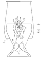
- FIGs 14, 15, and 16 correspond, respectively, to the first mode of operation, the second mode of operation, and the third mode of operation.
- baffle 126 In the first mode, baffle 126 is partially collapsed and translated forward to maintain bay and dilution flow pumping.
- baffle 126 In the second mode, baffle 126 is fully expanded to block hot engine parts.
- baffle 126 In the third mode, baffle 126 is fully collapsed and translated aft for minimal backpressure.
- Figure 14 corresponds to the first mode in which infrared suppression is achieved by blocking a direct view of an exhaust cavity using a cold shield that comprises cold baffle parts 142 and cold baffle nose 242.
- infrared suppressor 10 is effectively an ejector that is followed by a flow-path bend, in some configurations in which an additional hood 408 and panel 422 are provided.
- Flow deflector hood 408 is translated aft and rotated down, and lower panel 422 is rotated into a turning vane position, by extension of piston rods 420 that attach to attachment points 424 from piston cylinders 414 or by another suitable actuator or actuators that provide equivalent translation and rotation motions.
- This mode results in a large infrared signature reduction compared to conventional infrared suppression levels.
- a significant reduction from conventional infrared suppression levels is achieved in some configurations in the first mode when hood 408 and panel 422 are used in conjunction with the collapsible, translatable baffle.
- collapsible baffle 126 is opened up at a downstream end of stage I duct 14 to increase pumping and blocking a line-of-sight into an attached engine (not shown in the Figures).
- This second mode provides protection in a hostile environment without incurring all of the penalties of the redirected flow-path of the first mode.
- an approximately 74% infrared signature reduction from conventional infrared suppression levels is achieved at tail-on, and an approximately 71% infrared signature reduction at side view.
- an unsuppressed, low backpressure mode is achieved by actuating collapsible baffle 126 to its collapsed position (as shown in Figure 16) to reduce or minimize stage I duct 14 backpressure.
- the stage III duct 20 walls are aligned axially.
- Shaft horsepower is effectively increased or even maximized with reduced blockage by baffle 126. Additionally in some configurations, drag is reduced or minimized because flow is discharged along a centerline of suppressor 10.
- this reduction in drag is reduced by a retraction of piston rods 420 into piston cylinders 414 (or by another suitable actuation system), resulting in panel 422 becoming flush or essentially flush with a top side 428 of stage III wall 39 and hood 408 becoming flush with a bottom side 426 of stage III wall 39, with panel 422 forward rollers 416 and aft rollers 418 positioned as shown in Figure 16, and hood aft roller 410 engaging z-rail 404.
- Figure 18 does not show collapsible baffle 126 in its collapsed position as shown in Figure 16, because movement of baffle 126 can be independent of flow deflector hood 408 and lower panel 422 in some configurations.
- infrared suppression apparatus 10 is providing substantially the same exhaust configuration as a conventional IR suppressor, but with the baffle removed, which can provide installed engine performance slightly better than the that of an unsuppressed engine.
- deflector hood 408 and panel 422 are essentially oriented axially with respect to suppressor 10 to direct flow aft. In the first mode, however, deflector hood 408 and panel 422 are repositioned and/or rotated to turn the exhaust flow.
- Figure 20 is a rear view of an infrared suppression apparatus 10 that is representative of what is seen looking into the exhaust end of apparatus 10.
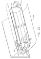
- Figures 21 and 22 are perspective views of stage III duct 20 in different stages of disassembly to allow internal components to be shown. The configuration shown in Figures 20 to 22 does not include the hood and panel assembly shown in Figures 17 to 19.
- mode selection can be selected manually by a pilot, automatically by a combination of a Full Authority Digital Engine Control (FADEC) and threat warning sensors, and/or by a combination of the foregoing.
- FADEC Full Authority Digital Engine Control
- the second mode provides a single element baffle 126 that eliminates characteristically higher temperatures of suppressors having multiple baffles.
- the lobed stage I duct exit mixer eliminates plume hot streaks, and the lobes are hidden from line of sight by the single element baffle.
- An increased bypass ratio of from about 0.8 to 1 to about 1.5 to 1 is provided for reduced hot metal and external plume signature.
- titanium metal is used in the construction of suppressor 10 for weight reduction.
- suppressor 10 is aligned 15 degrees further outboard to reduce fuselage heating.
- a coating or suite of coatings may be applied to enhance the device's emission suppression capabilities.
Landscapes
- Engineering & Computer Science (AREA)
- Chemical & Material Sciences (AREA)
- Combustion & Propulsion (AREA)
- Mechanical Engineering (AREA)
- General Engineering & Computer Science (AREA)
- Aiming, Guidance, Guns With A Light Source, Armor, Camouflage, And Targets (AREA)
- Exhaust Silencers (AREA)
- Lenses (AREA)
Applications Claiming Priority (1)
| Application Number | Priority Date | Filing Date | Title |
|---|---|---|---|
| US11/196,466 US7607306B2 (en) | 2005-08-03 | 2005-08-03 | Infrared suppressor apparatus and method |
Publications (3)
| Publication Number | Publication Date |
|---|---|
| EP1750003A2 true EP1750003A2 (fr) | 2007-02-07 |
| EP1750003A3 EP1750003A3 (fr) | 2010-09-08 |
| EP1750003B1 EP1750003B1 (fr) | 2018-07-25 |
Family
ID=37387399
Family Applications (1)
| Application Number | Title | Priority Date | Filing Date |
|---|---|---|---|
| EP06254000.0A Ceased EP1750003B1 (fr) | 2005-08-03 | 2006-07-31 | Dispositif permettant la supression d'infra-rouges |
Country Status (5)
| Country | Link |
|---|---|
| US (1) | US7607306B2 (fr) |
| EP (1) | EP1750003B1 (fr) |
| JP (1) | JP4771886B2 (fr) |
| BR (1) | BRPI0603420A (fr) |
| CA (1) | CA2554151C (fr) |
Cited By (3)
| Publication number | Priority date | Publication date | Assignee | Title |
|---|---|---|---|---|
| WO2009138068A1 (fr) * | 2008-05-15 | 2009-11-19 | Mtu Aero Engines Gmbh | Structure de tuyère mélangeuse |
| CN104033273A (zh) * | 2014-06-06 | 2014-09-10 | 中国航空工业集团公司沈阳发动机设计研究所 | 一种新型二元可调收敛喷管 |
| US12617550B2 (en) * | 2023-12-21 | 2026-05-05 | Tusas—Turk Havacilik Ve Uzay Sanayii Anonim Sirketi | Guidance system |
Families Citing this family (29)
| Publication number | Priority date | Publication date | Assignee | Title |
|---|---|---|---|---|
| US7313909B2 (en) * | 2004-10-25 | 2008-01-01 | General Electric Company | High-emissivity infrared coating applications for use in HIRSS applications |
| SE527787C2 (sv) * | 2004-11-05 | 2006-06-07 | Volvo Aero Corp | Utloppsanordning till en jetmotor och en jetmotor innefattande sådan utloppsanordning |
| US7607306B2 (en) * | 2005-08-03 | 2009-10-27 | General Electric Company | Infrared suppressor apparatus and method |
| US7607305B2 (en) * | 2005-08-03 | 2009-10-27 | General Electric Company | One-piece baffle infrared suppressor apparatus and method |
| FR2920035B1 (fr) * | 2007-08-17 | 2013-09-06 | Airbus France | Turbomoteur a emission de bruit reduite pour aeronef |
| US7937929B2 (en) * | 2007-11-16 | 2011-05-10 | Pratt & Whitney Canada Corp. | Exhaust duct with bypass channel |
| FR2924409B1 (fr) * | 2007-12-03 | 2010-05-14 | Airbus France | Nacelle d'aeronef comprenant des moyens d'evacuations d'air chaud |
| US8322126B2 (en) * | 2008-05-23 | 2012-12-04 | Rolls-Royce North American Technologies, Inc. | Gas turbine exhaust assembly |
| US8572947B2 (en) | 2008-12-31 | 2013-11-05 | Rolls-Royce Corporation | Gas turbine engine with ejector |
| US20100162680A1 (en) * | 2008-12-31 | 2010-07-01 | Syed Jalaluddin Khalid | Gas turbine engine with ejector |
| WO2012018615A1 (fr) | 2010-07-26 | 2012-02-09 | Rolls-Royce Corporation | Turbine à gaz comprenant un éjecteur |
| US20110162339A1 (en) * | 2011-01-07 | 2011-07-07 | Braden Manufacturing, Llc | Flow distribution of gas turbine exhaust using walls shaped to facilitate improved gas flow |
| EP2719620A3 (fr) | 2012-10-10 | 2017-10-18 | Sikorsky Aircraft Corporation | Système d'échappement tourné vers le haut pour aéronef à voilure tournante |
| US10562641B2 (en) * | 2012-10-10 | 2020-02-18 | Sikorsky Aircraft Corporation | AFT exhaust system for rotary wing aircraft |
| GB2506876A (en) * | 2012-10-10 | 2014-04-16 | Rolls Royce Plc | A gas turbine engine system transition duct |
| US9051047B2 (en) | 2012-11-12 | 2015-06-09 | Sikorsky Aircraft Corporation | Flexbeam rotor attachment to rotor blade |
| US9630706B2 (en) | 2013-02-22 | 2017-04-25 | Rolls-Royce Corporation | Positionable ejector member for ejector enhanced boundary layer alleviation |
| CN104033272A (zh) * | 2014-06-05 | 2014-09-10 | 中国航空工业集团公司沈阳发动机设计研究所 | 一种新型的二元可调收敛喷管 |
| CN104033285A (zh) * | 2014-06-05 | 2014-09-10 | 中国航空工业集团公司沈阳发动机设计研究所 | 一种新型的二元喷管 |
| CN104196649A (zh) * | 2014-06-05 | 2014-12-10 | 中国航空工业集团公司沈阳发动机设计研究所 | 一种新型二元遮挡旋流中心体结构 |
| US10480451B2 (en) | 2015-04-17 | 2019-11-19 | The Boeing Company | Systems and methods for restricting movement in flexible ducts |
| CN105114206B (zh) * | 2015-09-18 | 2017-06-16 | 中国航空工业集团公司沈阳发动机设计研究所 | 一种可降低红外和雷达信号特征的喷管 |
| EP3362668A4 (fr) * | 2015-10-13 | 2019-06-12 | Sikorsky Aircraft Corporation | Agencement de refroidissement d'échappement |
| US10577973B2 (en) | 2016-02-18 | 2020-03-03 | General Electric Company | Service tube for a turbine engine |
| CN106894917B (zh) * | 2017-02-17 | 2019-01-29 | 南京航空航天大学 | 一种低红外辐射信号的双出口s弯喷管及其控制方法 |
| US11608189B2 (en) * | 2020-08-11 | 2023-03-21 | Textron Innovations Inc | Multistage infrared suppression exhaust system |
| US11434018B1 (en) * | 2021-11-27 | 2022-09-06 | Airbus Defence and Space GmbH | Switchable air inlet device for engine air |
| CN114483367B (zh) * | 2021-12-29 | 2023-09-19 | 彩虹无人机科技有限公司 | 一种基于合成射流用于s弯喷管的红外抑制装置及方法 |
| US12180910B1 (en) | 2023-09-22 | 2024-12-31 | Rolls-Royce North American Technologies Inc. | Compact infrared suppressors with ring vanes for gas turbine engines |
Citations (2)
| Publication number | Priority date | Publication date | Assignee | Title |
|---|---|---|---|---|
| US4295332A (en) | 1978-11-13 | 1981-10-20 | General Electric Company | Infrared suppressor system |
| US6253540B1 (en) | 1982-07-08 | 2001-07-03 | General Electric Company | Removable baffle infrared suppressor |
Family Cites Families (13)
| Publication number | Priority date | Publication date | Assignee | Title |
|---|---|---|---|---|
| US4226084A (en) * | 1970-07-24 | 1980-10-07 | General Motors Corporation | Ducted fan engine exhaust mixer |
| US4800715A (en) * | 1981-08-10 | 1989-01-31 | The United States Of America As Represented By The Secretary Of The Army | Apparatus for suppressing infrared radiation emitted from gas turbine engines |
| US4537026A (en) * | 1982-04-07 | 1985-08-27 | Rolls-Royce Inc. | Variable area nozzles for turbomachines |
| US4502637A (en) * | 1982-06-07 | 1985-03-05 | Rolls-Royce Inc. | Turbomachine ejector nozzle with thrust reverser |
| US5746047A (en) * | 1982-07-08 | 1998-05-05 | Gereral Electric Company | Infrared suppressor |
| US5372006A (en) * | 1993-02-08 | 1994-12-13 | Aeronautical Concept Of Exhaust, Ltd. | Turbine engine equipped with thrust reverser |
| US6055804A (en) * | 1997-07-23 | 2000-05-02 | Sikorsky Aircraft Corporation | Turning vane arrangement for IR suppressors |
| US6615576B2 (en) * | 2001-03-29 | 2003-09-09 | Honeywell International Inc. | Tortuous path quiet exhaust eductor system |
| US7114323B2 (en) * | 2004-03-05 | 2006-10-03 | United Technologies Corporation | Jet exhaust noise reduction system and method |
| US6988674B2 (en) * | 2004-06-08 | 2006-01-24 | General Electric Company | Method and apparatus for suppressing infrared signatures |
| US7313909B2 (en) * | 2004-10-25 | 2008-01-01 | General Electric Company | High-emissivity infrared coating applications for use in HIRSS applications |
| US7607306B2 (en) * | 2005-08-03 | 2009-10-27 | General Electric Company | Infrared suppressor apparatus and method |
| US7681399B2 (en) * | 2006-11-14 | 2010-03-23 | General Electric Company | Turbofan engine cowl assembly and method of operating the same |
-
2005
- 2005-08-03 US US11/196,466 patent/US7607306B2/en active Active
-
2006
- 2006-07-27 CA CA2554151A patent/CA2554151C/fr not_active Expired - Fee Related
- 2006-07-31 EP EP06254000.0A patent/EP1750003B1/fr not_active Ceased
- 2006-08-02 BR BRPI0603420-9A patent/BRPI0603420A/pt not_active IP Right Cessation
- 2006-08-03 JP JP2006211816A patent/JP4771886B2/ja not_active Expired - Fee Related
Patent Citations (2)
| Publication number | Priority date | Publication date | Assignee | Title |
|---|---|---|---|---|
| US4295332A (en) | 1978-11-13 | 1981-10-20 | General Electric Company | Infrared suppressor system |
| US6253540B1 (en) | 1982-07-08 | 2001-07-03 | General Electric Company | Removable baffle infrared suppressor |
Cited By (4)
| Publication number | Priority date | Publication date | Assignee | Title |
|---|---|---|---|---|
| WO2009138068A1 (fr) * | 2008-05-15 | 2009-11-19 | Mtu Aero Engines Gmbh | Structure de tuyère mélangeuse |
| CN104033273A (zh) * | 2014-06-06 | 2014-09-10 | 中国航空工业集团公司沈阳发动机设计研究所 | 一种新型二元可调收敛喷管 |
| CN104033273B (zh) * | 2014-06-06 | 2016-06-08 | 中国航空工业集团公司沈阳发动机设计研究所 | 一种新型二元可调收敛喷管 |
| US12617550B2 (en) * | 2023-12-21 | 2026-05-05 | Tusas—Turk Havacilik Ve Uzay Sanayii Anonim Sirketi | Guidance system |
Also Published As
| Publication number | Publication date |
|---|---|
| CA2554151A1 (fr) | 2007-02-03 |
| US20070028623A1 (en) | 2007-02-08 |
| EP1750003A3 (fr) | 2010-09-08 |
| US7607306B2 (en) | 2009-10-27 |
| JP4771886B2 (ja) | 2011-09-14 |
| BRPI0603420A (pt) | 2007-03-27 |
| CA2554151C (fr) | 2014-04-01 |
| EP1750003B1 (fr) | 2018-07-25 |
| JP2007085336A (ja) | 2007-04-05 |
Similar Documents
| Publication | Publication Date | Title |
|---|---|---|
| EP1750003B1 (fr) | Dispositif permettant la supression d'infra-rouges | |
| US7762057B2 (en) | Internal mixing of a portion of fan exhaust flow and full core exhaust flow in aircraft turbofan engines | |
| EP1750002B1 (fr) | Dispositif compenant un déflecteur mono-pièce permettant la suppression d' infra-rouges | |
| JP4619089B2 (ja) | 固定ジオメトリ入口を備えたfladeガスタービンエンジン | |
| EP2966267B1 (fr) | Arrangements de buse pour un moteur à turbine à gaz et procédés de fonctionnement correspondants | |
| EP1655474B1 (fr) | Turboréacteur avec soufflante arrière de type flade et mécanisme d'orientation de la poussée | |
| EP2570641B1 (fr) | Carter de soufflante avec inverseur de poussée, soufflante et moteur à turbine à gaz associés | |
| EP1582730B1 (fr) | Appareil pour évacuer des gaz des turbomoteurs | |
| US20180094605A1 (en) | Turbofan engine for a civil supersonic aircraft | |
| GB2437295A (en) | Aeroengine ventilation system | |
| US9574518B2 (en) | Turbofan engine with variable exhaust cooling | |
| US10539095B2 (en) | Aircraft gas turbine engine nacelle | |
| US11486307B2 (en) | Aircraft comprising a gas turbine engine having an axially adjustable intake and a nacelle | |
| EP1726812B1 (fr) | Système d'inversion de poussée pour un avion | |
| US9574520B2 (en) | Reverse core engine thrust reverser for under wing | |
| US20140250863A1 (en) | Rear mounted reverse core engine thrust reverser | |
| US10156206B2 (en) | Pivoting blocker door | |
| EP1809893B1 (fr) | Stator pour moteur a reaction, moteur a reaction pourvu de ce stator, et aeronef equipe de ce moteur a reaction | |
| US12018629B2 (en) | Thrust reverser comprising a single actuator for controlling a mobile cowling | |
| EP4180639B1 (fr) | Dispositif d'admission d'air pour un conduit d'admission d'un moteur d'aéronef | |
| EP3148880B1 (fr) | Échappement convertible pour giravion | |
| EP2971728B1 (fr) | Module d'inverseur de poussée double cible | |
| Yepifanov et al. | Afterburners and exhaust systems of turbine engines |
Legal Events
| Date | Code | Title | Description |
|---|---|---|---|
| PUAI | Public reference made under article 153(3) epc to a published international application that has entered the european phase |
Free format text: ORIGINAL CODE: 0009012 |
|
| AK | Designated contracting states |
Kind code of ref document: A2 Designated state(s): AT BE BG CH CY CZ DE DK EE ES FI FR GB GR HU IE IS IT LI LT LU LV MC NL PL PT RO SE SI SK TR |
|
| AX | Request for extension of the european patent |
Extension state: AL BA HR MK YU |
|
| PUAL | Search report despatched |
Free format text: ORIGINAL CODE: 0009013 |
|
| AK | Designated contracting states |
Kind code of ref document: A3 Designated state(s): AT BE BG CH CY CZ DE DK EE ES FI FR GB GR HU IE IS IT LI LT LU LV MC NL PL PT RO SE SI SK TR |
|
| AX | Request for extension of the european patent |
Extension state: AL BA HR MK RS |
|
| 17P | Request for examination filed |
Effective date: 20110308 |
|
| AKX | Designation fees paid |
Designated state(s): DE FR GB IT SE TR |
|
| 17Q | First examination report despatched |
Effective date: 20170113 |
|
| REG | Reference to a national code |
Ref country code: DE Ref legal event code: R079 Ref document number: 602006055888 Country of ref document: DE Free format text: PREVIOUS MAIN CLASS: F02K0001820000 Ipc: F02K0001380000 |
|
| RIC1 | Information provided on ipc code assigned before grant |
Ipc: F02K 1/82 20060101ALI20180130BHEP Ipc: F02K 1/38 20060101AFI20180130BHEP |
|
| GRAP | Despatch of communication of intention to grant a patent |
Free format text: ORIGINAL CODE: EPIDOSNIGR1 |
|
| INTG | Intention to grant announced |
Effective date: 20180320 |
|
| GRAS | Grant fee paid |
Free format text: ORIGINAL CODE: EPIDOSNIGR3 |
|
| GRAA | (expected) grant |
Free format text: ORIGINAL CODE: 0009210 |
|
| AK | Designated contracting states |
Kind code of ref document: B1 Designated state(s): DE FR GB IT SE TR |
|
| REG | Reference to a national code |
Ref country code: GB Ref legal event code: FG4D |
|
| REG | Reference to a national code |
Ref country code: DE Ref legal event code: R096 Ref document number: 602006055888 Country of ref document: DE |
|
| REG | Reference to a national code |
Ref country code: FR Ref legal event code: PLFP Year of fee payment: 13 |
|
| PG25 | Lapsed in a contracting state [announced via postgrant information from national office to epo] |
Ref country code: SE Free format text: LAPSE BECAUSE OF FAILURE TO SUBMIT A TRANSLATION OF THE DESCRIPTION OR TO PAY THE FEE WITHIN THE PRESCRIBED TIME-LIMIT Effective date: 20180725 |
|
| REG | Reference to a national code |
Ref country code: DE Ref legal event code: R097 Ref document number: 602006055888 Country of ref document: DE |
|
| PG25 | Lapsed in a contracting state [announced via postgrant information from national office to epo] |
Ref country code: IT Free format text: LAPSE BECAUSE OF FAILURE TO SUBMIT A TRANSLATION OF THE DESCRIPTION OR TO PAY THE FEE WITHIN THE PRESCRIBED TIME-LIMIT Effective date: 20180725 |
|
| PLBE | No opposition filed within time limit |
Free format text: ORIGINAL CODE: 0009261 |
|
| STAA | Information on the status of an ep patent application or granted ep patent |
Free format text: STATUS: NO OPPOSITION FILED WITHIN TIME LIMIT |
|
| 26N | No opposition filed |
Effective date: 20190426 |
|
| PGFP | Annual fee paid to national office [announced via postgrant information from national office to epo] |
Ref country code: FR Payment date: 20190621 Year of fee payment: 14 |
|
| PGFP | Annual fee paid to national office [announced via postgrant information from national office to epo] |
Ref country code: DE Payment date: 20190620 Year of fee payment: 14 Ref country code: GB Payment date: 20190624 Year of fee payment: 14 |
|
| PG25 | Lapsed in a contracting state [announced via postgrant information from national office to epo] |
Ref country code: TR Free format text: LAPSE BECAUSE OF FAILURE TO SUBMIT A TRANSLATION OF THE DESCRIPTION OR TO PAY THE FEE WITHIN THE PRESCRIBED TIME-LIMIT Effective date: 20180725 |
|
| REG | Reference to a national code |
Ref country code: DE Ref legal event code: R119 Ref document number: 602006055888 Country of ref document: DE |
|
| GBPC | Gb: european patent ceased through non-payment of renewal fee |
Effective date: 20200731 |
|
| PG25 | Lapsed in a contracting state [announced via postgrant information from national office to epo] |
Ref country code: FR Free format text: LAPSE BECAUSE OF NON-PAYMENT OF DUE FEES Effective date: 20200731 Ref country code: GB Free format text: LAPSE BECAUSE OF NON-PAYMENT OF DUE FEES Effective date: 20200731 |
|
| PG25 | Lapsed in a contracting state [announced via postgrant information from national office to epo] |
Ref country code: DE Free format text: LAPSE BECAUSE OF NON-PAYMENT OF DUE FEES Effective date: 20210202 |