EP1750004B1 - Collecteur d'admission en résine - Google Patents
Collecteur d'admission en résine Download PDFInfo
- Publication number
- EP1750004B1 EP1750004B1 EP06014377A EP06014377A EP1750004B1 EP 1750004 B1 EP1750004 B1 EP 1750004B1 EP 06014377 A EP06014377 A EP 06014377A EP 06014377 A EP06014377 A EP 06014377A EP 1750004 B1 EP1750004 B1 EP 1750004B1
- Authority
- EP
- European Patent Office
- Prior art keywords
- intake
- intake manifold
- negative pressure
- raised portion
- surge tank
- Prior art date
- Legal status (The legal status is an assumption and is not a legal conclusion. Google has not performed a legal analysis and makes no representation as to the accuracy of the status listed.)
- Not-in-force
Links
- 239000011347 resin Substances 0.000 title claims description 8
- 229920005989 resin Polymers 0.000 title claims description 8
- XLYOFNOQVPJJNP-UHFFFAOYSA-N water Chemical compound O XLYOFNOQVPJJNP-UHFFFAOYSA-N 0.000 claims description 22
- 230000000630 rising effect Effects 0.000 claims description 20
- 238000002485 combustion reaction Methods 0.000 claims description 11
- 238000005192 partition Methods 0.000 claims description 6
- 238000010926 purge Methods 0.000 claims description 5
- 238000011144 upstream manufacturing Methods 0.000 claims description 5
- 239000007789 gas Substances 0.000 description 44
- 238000004519 manufacturing process Methods 0.000 description 5
- 239000003595 mist Substances 0.000 description 3
- 238000010276 construction Methods 0.000 description 2
- 238000000034 method Methods 0.000 description 2
- 230000008569 process Effects 0.000 description 2
- 230000008014 freezing Effects 0.000 description 1
- 238000007710 freezing Methods 0.000 description 1
- 230000006872 improvement Effects 0.000 description 1
- 230000002401 inhibitory effect Effects 0.000 description 1
- 239000002184 metal Substances 0.000 description 1
- 238000012986 modification Methods 0.000 description 1
- 230000004048 modification Effects 0.000 description 1
- 230000002093 peripheral effect Effects 0.000 description 1
- 230000004044 response Effects 0.000 description 1
- 238000013518 transcription Methods 0.000 description 1
- 230000035897 transcription Effects 0.000 description 1
Images





Classifications
-
- F—MECHANICAL ENGINEERING; LIGHTING; HEATING; WEAPONS; BLASTING
- F02—COMBUSTION ENGINES; HOT-GAS OR COMBUSTION-PRODUCT ENGINE PLANTS
- F02M—SUPPLYING COMBUSTION ENGINES IN GENERAL WITH COMBUSTIBLE MIXTURES OR CONSTITUENTS THEREOF
- F02M35/00—Combustion-air cleaners, air intakes, intake silencers, or induction systems specially adapted for, or arranged on, internal-combustion engines
- F02M35/10—Air intakes; Induction systems
- F02M35/104—Intake manifolds
- F02M35/112—Intake manifolds for engines with cylinders all in one line
-
- F—MECHANICAL ENGINEERING; LIGHTING; HEATING; WEAPONS; BLASTING
- F02—COMBUSTION ENGINES; HOT-GAS OR COMBUSTION-PRODUCT ENGINE PLANTS
- F02M—SUPPLYING COMBUSTION ENGINES IN GENERAL WITH COMBUSTIBLE MIXTURES OR CONSTITUENTS THEREOF
- F02M35/00—Combustion-air cleaners, air intakes, intake silencers, or induction systems specially adapted for, or arranged on, internal-combustion engines
- F02M35/10—Air intakes; Induction systems
- F02M35/10006—Air intakes; Induction systems characterised by the position of elements of the air intake system in direction of the air intake flow, i.e. between ambient air inlet and supply to the combustion chamber
- F02M35/10026—Plenum chambers
- F02M35/10039—Intake ducts situated partly within or on the plenum chamber housing
-
- F—MECHANICAL ENGINEERING; LIGHTING; HEATING; WEAPONS; BLASTING
- F02—COMBUSTION ENGINES; HOT-GAS OR COMBUSTION-PRODUCT ENGINE PLANTS
- F02M—SUPPLYING COMBUSTION ENGINES IN GENERAL WITH COMBUSTIBLE MIXTURES OR CONSTITUENTS THEREOF
- F02M35/00—Combustion-air cleaners, air intakes, intake silencers, or induction systems specially adapted for, or arranged on, internal-combustion engines
- F02M35/10—Air intakes; Induction systems
- F02M35/10209—Fluid connections to the air intake system; their arrangement of pipes, valves or the like
- F02M35/10222—Exhaust gas recirculation [EGR]; Positive crankcase ventilation [PCV]; Additional air admission, lubricant or fuel vapour admission
-
- F—MECHANICAL ENGINEERING; LIGHTING; HEATING; WEAPONS; BLASTING
- F02—COMBUSTION ENGINES; HOT-GAS OR COMBUSTION-PRODUCT ENGINE PLANTS
- F02M—SUPPLYING COMBUSTION ENGINES IN GENERAL WITH COMBUSTIBLE MIXTURES OR CONSTITUENTS THEREOF
- F02M35/00—Combustion-air cleaners, air intakes, intake silencers, or induction systems specially adapted for, or arranged on, internal-combustion engines
- F02M35/10—Air intakes; Induction systems
- F02M35/10209—Fluid connections to the air intake system; their arrangement of pipes, valves or the like
- F02M35/10229—Fluid connections to the air intake system; their arrangement of pipes, valves or the like the intake system acting as a vacuum or overpressure source for auxiliary devices, e.g. brake systems; Vacuum chambers
-
- F—MECHANICAL ENGINEERING; LIGHTING; HEATING; WEAPONS; BLASTING
- F02—COMBUSTION ENGINES; HOT-GAS OR COMBUSTION-PRODUCT ENGINE PLANTS
- F02M—SUPPLYING COMBUSTION ENGINES IN GENERAL WITH COMBUSTIBLE MIXTURES OR CONSTITUENTS THEREOF
- F02M35/00—Combustion-air cleaners, air intakes, intake silencers, or induction systems specially adapted for, or arranged on, internal-combustion engines
- F02M35/10—Air intakes; Induction systems
- F02M35/1034—Manufacturing and assembling intake systems
- F02M35/10354—Joining multiple sections together
-
- F—MECHANICAL ENGINEERING; LIGHTING; HEATING; WEAPONS; BLASTING
- F02—COMBUSTION ENGINES; HOT-GAS OR COMBUSTION-PRODUCT ENGINE PLANTS
- F02M—SUPPLYING COMBUSTION ENGINES IN GENERAL WITH COMBUSTIBLE MIXTURES OR CONSTITUENTS THEREOF
- F02M35/00—Combustion-air cleaners, air intakes, intake silencers, or induction systems specially adapted for, or arranged on, internal-combustion engines
- F02M35/02—Air cleaners
-
- F—MECHANICAL ENGINEERING; LIGHTING; HEATING; WEAPONS; BLASTING
- F02—COMBUSTION ENGINES; HOT-GAS OR COMBUSTION-PRODUCT ENGINE PLANTS
- F02M—SUPPLYING COMBUSTION ENGINES IN GENERAL WITH COMBUSTIBLE MIXTURES OR CONSTITUENTS THEREOF
- F02M35/00—Combustion-air cleaners, air intakes, intake silencers, or induction systems specially adapted for, or arranged on, internal-combustion engines
- F02M35/10—Air intakes; Induction systems
- F02M35/10091—Air intakes; Induction systems characterised by details of intake ducts: shapes; connections; arrangements
- F02M35/10111—Substantially V-, C- or U-shaped ducts in direction of the flow path
Definitions
- the invention relates to an intake manifold used in an internal combustion engine or the like mounted in a vehicle such as an automobile, for example.
- the engine to be mounted is provided with an intake manifold for supplying air to a combustion chamber.
- the intake manifold is such that a plurality of intake passages which are connected to a plurality of intake ports of the internal combustion engine are formed integrated with a surge tank which is disposed upstream of those intake passages and to which an outside air intake path is connected.
- An intake manifold is provided with a gas introduction hole and an intake air negative pressure outlet hole.
- the gas introduction hole is provided for introducing gas containing water vapor or oil content in the form of mist, such as EGR gas (re-circulated exhaust gas), purge air from a canister, or blow-by gas in the crankcase, or the like.
- the intake air negative pressure outlet hole is provided for applying intake air negative pressure within the surge tank to a brake booster or the like, for example.
- the gas introduction hole and the intake air negative pressure outlet hole are preferably arranged in locations that are relatively far apart from each other so that the water vapor that is mixed in with the gas introduced from the gas introduction hole is less apt to adhere to the inside opening of the intake air negative pressure outlet hole. This arrangement may be difficult to achieve, however, depending on how the intake manifold is mounted.
- the water vapor mixed in with the gas that is introduced from the gas introduction hole may adhere to the inside surface of a wall portion that forms the surge tank and form water droplets. If these water droplets trickle down the inside surface of the wall portion and adhere to the inside opening of the intake air negative pressure outlet hole, they may freeze and block the opening.
- the baffle plate and partition wall portion have comparatively complicated shapes, which means that a mold must be designed taking into account workability when opening the mold. As a result, designing the mold is difficult and increases manufacturing costs. Thus there remains room for improvement.
- This invention thus provides an intake manifold with a surge tank used in an internal combustion engine, which has a structure which i) makes it possible to prevent a phenomenon in which water droplets that trickle down an inside surface of a wall portion that forms the surge tank freeze and block the inside opening of an intake air negative pressure outlet hole, as well as which ii) can be manufactured relatively easily.
- a first aspect of the invention relates to an intake manifold in which an intake passage that is connected to an intake port of an internal combustion engine is integrally formed with a surge tank which is arranged on the upstream side of the intake passage and which is connected to an outside air intake path.
- This intake manifold is characterised by including i) a raised portion provided in a first predetermined location on an inside surface of a wall portion which forms the surge tank, ii) a gas introduction hole provided in a second predetermined location, other than in the raised portion, in the inside surface of the wall portion, iii) an intake air negative pressure outlet hole provided in the raised portion, and iv) guiding means for catching moisture that trickles down the inside surface of the wall portion above the raised portion and guiding the moisture to a location away from the intake air negative pressure outlet hole, provided in a region above the intake air negative pressure outlet hole in the rising surface of the raised portion.
- the guide means may be formed by a groove.
- the inside surface of the wall portion in which the gas introduction hole is provided and the raised portion in which the intake air negative pressure outlet hole is provided are on different planes.
- the water droplets adhering to the inside surface of the wall portion trickle down the inside surface of the wall portion, although they will run down to the rising surface of the raised portion, those water droplets are inhibited from reaching the inside opening of the intake air negative pressure outlet hole.
- the water droplets that have run down to the rising surface of the raised portion are guided by the guide means provided in the rising surface so that they run down away from the intake air negative pressure outlet hole, not toward the tip end side in the rising direction of the raised portion. Accordingly, it is possible to avoid a phenomenon in which the inside opening of the intake air negative pressure outlet hole becomes blocked by frozen moisture.
- the guide means may be formed by a dam which juts upward from the rising surface of the raised portion.
- the intake manifold may be formed of an upper case and a lower case, the intake passage and the surge tank may be provided partially divided in these cases, and the gas introduction hole and the intake air negative pressure outlet hole may be formed on one wall portion that forms the surge tank on the lower case side.
- This structure identifies an example in which the gas introduction hole is arranged relatively close to the intake air negative pressure outlet hole. In this case as well, moisture can be inhibited from coming near the inside opening of the intake air negative pressure outlet hole because of the step-like structure described above.
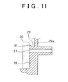
- a partition wall that separates the intake air negative pressure outlet hole and the gas introduction hole may be provided between those holes.
- This structure makes it possible to avoid moisture contained in gas that is introduced from the gas introduction hole from directly adhering to the intake air negative pressure outlet hole.
- the intake manifold according to the invention makes it possible to prevent a phenomenon in which moisture in the surge tank freezes and blocks the inside opening of the intake air negative pressure outlet hole. Moreover, that structure can be made relatively simply. Thus, when the intake manifold is made by resin forming, it is possible to make the structure simple such that the mold can be opened easily and the manufacturing costs of the mold can be reduced, in turn enabling the cost of the product to be reduced.
- the internal combustion engine with which the intake manifold is used is a 4-cylinder gasoline engine to be mounted in a vehicle, for example.
- the engine is not limited to this. For example, it may have a different number of cylinders, or may be a diesel engine.
- an engine 1 is provided with a cylinder block 2 and a cylinder head 3.
- the cylinder block 2 has a plurality of (in this case, four) cylinders 4, each of which has a piston 5 inserted therein which can move reciprocally.
- a combustion chamber 6 is formed in each cylinder 4 by the space between the upper end of the piston 5 and the cylinder head 3.
- an intake port 7 and an exhaust port 8 are provided for each combustion chamber 6.
- the inside openings (on the combustion chamber 6 side) of the intake port 7 and the exhaust port 8 are opened and closed by an intake valve 9 and an exhaust valve 10, respectively.
- An intake manifold 11 is attached to the intake ports 7 and an exhaust manifold 12 is attached to the exhaust ports 8.
- an air intake system which includes an intake pipe, a throttle body which opens and closes in response to an operation of an accelerator peddle, and an air cleaner and the like is attached to the intake manifold 11.
- the intake manifold 11 is structured such that a plurality of (i.e., four in this case) intake passages 21 that are connected to the intake ports 7 of the engine 1 are integrally formed with a surge tank 22 which is arranged upstream of the intake passages 21 and which are connected to the throttle body via the intake pipe of the air intake system described above.
- the surge tank 22 is formed of a single cavity of a predetermined capacity.
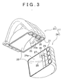
- the intake manifold 11 has a two-piece construction in which an upper case 23 and a lower case 24 are combined, as shown in FIG. 2 or FIG. 3 .
- the intake passages 21 and the surge tank 22 are provided partially divided in these cases 23 and 24.
- a gas introduction hole 26 and an air introduction portion 25 for introducing air from the outside into the surge tank 22 are formed in the upper case 23.
- the throttle body, not shown, and the air cleaner, also not shown, are attached to the air introduction portion 25 via the intake pipe, not shown, of the air intake system described above.
- various hoses such as a blow-by gas recirculation hole, a purge air hose, an exhaust gas recirculation hose, and the like, for example, are connected to the gas introduction hole 26.
- Gas containing water vapor or oil content in the form of mist such as re-circulated exhaust gas, purge air from a canister, blow-by gas within the crank case, or the like, are introduced through this gas introduction hole 26 into the surge tank 22.
- the lower case 24 has a hollow semi-circular column shape.
- the upstream portions of the four intake passages 21 are integrally formed along the inner peripheral surface of the semi-circular portion of the lower case 24.
- An intake air negative pressure outlet hole 27 is formed in the thickness direction through one side wall portion (one wall forming the surge tank 22) 24a of the two side wall portions of this lower case 24 which oppose each other substantially parallel.
- a brake booster for example, is connected via a brake hose, to the intake air negative pressure outlet hole 27 such that the surge tank 22 and the brake booster are connected via the intake air negative pressure outlet hole 27.
- one side wall portion 23a of the upper case 23 in which the gas introduction hole 26 is formed and the one side wall portion 24a of the lower case 24 in which the intake air negative pressure outlet hole 27 is formed are fitted together so as to form one continuous wall portion. Accordingly, the holes 26 and 27 are provided in a row while being relatively far apart from one another.
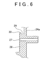
- a raised portion 28 is provided in a predetermined location on the inside surface of the one side wall portion 24a that forms the surge tank 22 of the lower case 24.
- This raised portion 28 is raised and thus not on the same plane as the rest of the inside surface of the one side wall portion 24a.
- the intake air negative pressure outlet hole 27 is formed in this raised portion 28.
- this raised portion 28 is formed in a strip with the upper end side formed in a semi-circle.
- the gas introduction hole 26 is formed in the inside surface of the one side wall portion 23a that forms the surge tank 22 of the upper case 23.
- This one side wall portion 23a is on the same plane as the inside surface of the one side wall portion 24a of the lower case 24 described above so the gas introduction hole 26 is not on the same plane as the raised portion 28.
- the inside opening of the gas introduction hole 26 and the inside opening of the intake air negative pressure outlet hole 27 are not on the same plane.
- a guide groove 29 is formed in a region above the intake air negative pressure outlet hole 27 in the rising surface of the raised portion 28.
- This guide groove 29 catches moisture that adheres to the inside surface of the one side wall portion 24a of the lower case 24 positioned above the raised portion 28 and trickles down the inside surface, and guides it to a location away from the intake air negative pressure outlet hole 27.
- the guide groove 29 is obtained by providing a dam 30 that juts upward at the tip end side in the rising direction on the rising surface of the raised portion 28.
- the upper end of the raised portion 28 is semi-circular so the rising surface of the raised portion 28 is also semi-circular, and the dam 30 is provided along this rising surface. Therefore, the guide groove 29 curves in an inverted U-shape such that moisture that had trickled down to the guide groove 29 then runs down both end sides of the raised portion 28 by its own weight.
- the dam 30 is provided on the tip end edge in the rising direction on the rising surface of the raised portion 28, but it may also be provided in a position farther inward toward the base side of the raised portion 28 than the tip end edge.
- gas containing water vapor or oil content in the form of mist such as EGR gas (re-circulated exhaust gas), purge air from a canister, not shown, or blow-by gas in the crankcase, also not shown, or the like is introduced from the gas introduction hole 26 into the surge tank 22.
- EGR gas re-circulated exhaust gas
- purge air from a canister, not shown, or blow-by gas in the crankcase, also not shown, or the like is introduced from the gas introduction hole 26 into the surge tank 22.
- the water vapor contained in these gases may adhere to the inside surface of the upper case 23 and the lower case 24 which form the surge tank 22 and become water droplets.
- this structure thus makes it possible to prevent a phenomenon in which the inside opening of the intake air negative pressure outlet hole 27 becomes blocked by frozen moisture.
- this example embodiment makes it possible to prevent the phenomenon in which those water droplets freeze at the inside opening of the intake air negative pressure outlet hole 27. Therefore, intake air negative pressure inside the surge tank 22 can be reliably released from the intake air negative pressure outlet hole 27, which makes it possible to ensure stable operation of a brake booster, for example.
- the dam 30 and the raised portion 28 which is on a different plane than the inside surface of the one side wall portion 24a are provided. Accordingly, if the intake manifold 11 were manufactured by resin forming, it is possible to make the structure simple such that the mold can be opened easily and the manufacturing costs of the mold can be reduced.
- the lower case 24 is formed by a concave receiving mold and a convex press mold.
- the mold can be opened easily if it is designed such that a transcription pattern for obtaining the linearly shaped raised portion 28 and the dam 30 which is provided inside these molds is parallel with the direction of mold release.
- the partition wall 31 simply juts out straight so when the intake manifold 11 is manufactured by a resin forming, it is possible to make the structure simple such that the mold can be opened easily and the manufacturing costs of the mold can be reduced, in turn enabling the cost of the product to be reduced.
Landscapes
- Engineering & Computer Science (AREA)
- Chemical & Material Sciences (AREA)
- Combustion & Propulsion (AREA)
- Mechanical Engineering (AREA)
- General Engineering & Computer Science (AREA)
- Manufacturing & Machinery (AREA)
- Lubrication Details And Ventilation Of Internal Combustion Engines (AREA)
- Exhaust-Gas Circulating Devices (AREA)
- Moulds For Moulding Plastics Or The Like (AREA)
Claims (12)
- Collecteur d'admission dans lequel un passage d'admission (21) qui est relié à un orifice d'admission (7) d'un moteur à combustion intérieure (1) est intégralement formé avec un réservoir d'expansion (22) qui est agencé sur un côté en amont du passage d'admission (21) et qui est relié à un chemin d'admission d'air externe, caractérisé par le fait de comprendre:une portion surélevée (28) pourvue dans un premier emplacement prédéterminé sur une surface intérieure d'une portion de paroi qui forme le réservoir d'expansion (22);un trou d'introduction de gaz (26) pourvu dans un deuxième emplacement prédéterminé, autre que dans la portion surélevée (28), dans la surface intérieure de la portion de paroi;un trou de sortie à pression négative d'air d'admission (27) pourvu dans la portion surélevée (28); etun moyen de guidage pour attraper l'humidité qui s'infiltre sous la surface intérieure de la portion de paroi au-dessus de la portion surélevée (28) et guider l'humidité à un emplacement éloigné du trou de sortie à pression négative d'air d'admission (27), pourvu dans une région au-dessus du trou de sortie à pression négative d'air d'admission (27) dans la surface montante de la portion surélevée (28).
- Collecteur d'admission selon la revendication 1, caractérisé en ce que le moyen de guidage est formé par une rainure.
- Collecteur d'admission selon la revendication 1, caractérisé en ce que le moyen de guidage est formé par un barrage (30) qui ait saillie vers le haut à partir de la surface montante de la portion surélevée (28).
- Collecteur d'admission selon la revendication 3, caractérisé en ce que le barrage (30) est formé sur un côté d'extrémité de pointe dans la direction montante sur la surface montante de la portion surélevée (28).
- Collecteur d'admission selon l'une quelconque des revendications 1 à 4, caractérisé en ce que:le collecteur d'admission est formé d'un boîtier supérieur (23) et d'un boîtier inférieur (24);une portion supérieure du passage d'admission (21) et une portion supérieure du réservoir d'expansion (22) sont pourvues dans le boîtier supérieur (23);une portion inférieure du passage d'admission (21) et une portion inférieure du réservoir d'expansion (22) sont pourvues dans le boîtier inférieur (24); etle trou d'introduction de gaz (26) et le trou de sortie à pression négative d'air d'admission (27) sont formés dans une portion de paroi (24a) qui forme le réservoir d'expansion (22) sur le côté du boîtier inférieur (24).
- Collecteur d'admission selon l'une quelconque des revendications 1 à 5, caractérisé par le fait de comprendre en plus:une paroi de séparation (31) pourvue entre le trou de sortie à pression négative d'air d'admission (27) et le trou d'introduction de gaz (26) qui sépare ces trous (26, 27).
- Collecteur d'admission selon l'une quelconque des revendications 1 à 6, caractérisé en ce que la surface montante de la portion surélevée (28) est semi-circulaire.
- Collecteur d'admission selon l'une quelconque des revendications 1 à 7, caractérisé en ce que le collecteur d'admission est fait en résine.
- Collecteur d'admission selon l'une quelconque des revendications 1 à 8, caractérisé en ce qu'une surface supérieure de la portion surélevée se trouve sur un plan différent de la surface intérieure de la portion de paroi qui forme le réservoir d'expansion (22).
- Collecteur d'admission selon l'une quelconque des revendications 1 à 9, caractérisé en ce que le trou d'introduction de gaz (26) est un trou qui introduit au moins l'un d'un gaz de soufflage, d'air de purge, et de gaz d'échappement recirculé qui inclut au moins de la vapeur d'eau dans le réservoir d'expansion (22).
- Collecteur d'admission selon l'une quelconque des revendications 1 à 10, caractérisé en ce que le trou de sortie à pression négative d'air d'admission (27) est un trou formé à travers la surface supérieure de la portion surélevée (28), dans la direction d'épaisseur de la portion surélevée (28).
- Collecteur d'admission selon l'une quelconque des revendications 1 à 11, caractérisé en ce que le trou de sortie à pression négative d'air d'admission (27) est un trou qui libère une pression négative d'air d'admission dans le réservoir d'expansion (22) à l'extérieur du réservoir d'expansion (22).
Applications Claiming Priority (1)
| Application Number | Priority Date | Filing Date | Title |
|---|---|---|---|
| JP2005223771A JP4422654B2 (ja) | 2005-08-02 | 2005-08-02 | インテークマニホルド |
Publications (2)
| Publication Number | Publication Date |
|---|---|
| EP1750004A1 EP1750004A1 (fr) | 2007-02-07 |
| EP1750004B1 true EP1750004B1 (fr) | 2008-04-23 |
Family
ID=37309351
Family Applications (1)
| Application Number | Title | Priority Date | Filing Date |
|---|---|---|---|
| EP06014377A Not-in-force EP1750004B1 (fr) | 2005-08-02 | 2006-07-11 | Collecteur d'admission en résine |
Country Status (5)
| Country | Link |
|---|---|
| US (1) | US7357110B2 (fr) |
| EP (1) | EP1750004B1 (fr) |
| JP (1) | JP4422654B2 (fr) |
| CN (1) | CN100545441C (fr) |
| DE (1) | DE602006000983T2 (fr) |
Families Citing this family (27)
| Publication number | Priority date | Publication date | Assignee | Title |
|---|---|---|---|---|
| US7779806B2 (en) * | 2007-01-05 | 2010-08-24 | Mann + Hummel Gmbh | Air intake manifold including a plenum reducer insert |
| JP4963976B2 (ja) * | 2007-01-26 | 2012-06-27 | ヤマハ発動機株式会社 | 樹脂ブロックベルトを有するベルト式無段変速機を備えた鞍乗型車両 |
| JP4792427B2 (ja) * | 2007-06-15 | 2011-10-12 | トヨタ自動車株式会社 | 配管防水接続構造 |
| JP4823159B2 (ja) * | 2007-07-17 | 2011-11-24 | 本田技研工業株式会社 | 内燃機関の吸気装置 |
| JP4814164B2 (ja) * | 2007-07-17 | 2011-11-16 | 本田技研工業株式会社 | 内燃機関の吸気装置 |
| JP4837646B2 (ja) * | 2007-10-05 | 2011-12-14 | 株式会社ケーヒン | エンジン用吸気マニフォルド |
| CA2719134C (fr) * | 2008-03-21 | 2015-06-30 | The University Of Chicago | Traitement avec des antagonistes des opioides et des inhibiteurs mtor |
| JP4840676B2 (ja) * | 2008-12-17 | 2011-12-21 | アイシン精機株式会社 | 吸気マニホルド |
| JP4892020B2 (ja) * | 2009-02-25 | 2012-03-07 | 日本サーモスタット株式会社 | 内燃機関における冷却水通路装置 |
| US8511289B2 (en) * | 2009-05-18 | 2013-08-20 | Aisan Kogyo Kabushiki Kaisha | Intake manifolds |
| US8677967B2 (en) | 2010-01-28 | 2014-03-25 | Aisin Seiki Kabushiki Kaisha | Intake manifold having negative pressure relief |
| JP5617382B2 (ja) * | 2010-06-28 | 2014-11-05 | トヨタ紡織株式会社 | インテークマニホールド |
| WO2012028639A1 (fr) * | 2010-09-02 | 2012-03-08 | Mann+Hummel Gmbh | Collecteur d'admission d'air pour moteur à combustion interne |
| JP5691435B2 (ja) * | 2010-11-24 | 2015-04-01 | トヨタ自動車株式会社 | 内燃機関の吸気装置 |
| DE102011014541B4 (de) * | 2011-03-19 | 2019-01-17 | Audi Ag | Luftzufuhrelement für eine Verbrennungskraftmaschine und Verfahren zum Fertigen eines Luftzufuhrelements |
| JP5814106B2 (ja) * | 2011-12-26 | 2015-11-17 | トヨタ自動車株式会社 | インテークマニホールド |
| US8967109B2 (en) * | 2013-05-31 | 2015-03-03 | Ford Global Technologies, Llc | Component catch for crash robustness |
| DE102013113827A1 (de) * | 2013-12-11 | 2015-06-11 | Dr. Ing. H.C. F. Porsche Aktiengesellschaft | Kraftfahrzeug mit einer Tankentlüftungsvorrichtung |
| WO2015145662A1 (fr) * | 2014-03-27 | 2015-10-01 | 日産自動車株式会社 | Dispositif d'admission d'air pour moteur à combustion interne |
| US9528406B2 (en) * | 2014-05-22 | 2016-12-27 | Ford Global Technologies, Llc | Systems and methods for purge and PCV control |
| US10001093B2 (en) * | 2016-01-21 | 2018-06-19 | Ford Global Technologies, Llc | Intake manifold having slosh prevention baffles |
| JP6754631B2 (ja) * | 2016-06-29 | 2020-09-16 | ダイハツ工業株式会社 | 多気筒内燃機関用の吸気マニホールド |
| JP7200548B2 (ja) * | 2018-08-29 | 2023-01-10 | 株式会社アイシン | インテークマニホールド |
| JP7124573B2 (ja) * | 2018-09-05 | 2022-08-24 | トヨタ紡織株式会社 | 吸気マニホールド |
| US11220983B2 (en) * | 2019-04-22 | 2022-01-11 | Zhejiang CFMOTO Power Co., Ltd. | Air intake system for off road vehicle |
| JP7107911B2 (ja) * | 2019-12-17 | 2022-07-27 | ダイハツ工業株式会社 | 自動車用内燃機関の吸気マニホールド |
| JP7746904B2 (ja) * | 2022-04-01 | 2025-10-01 | マツダ株式会社 | エンジンの吸気装置 |
Family Cites Families (11)
| Publication number | Priority date | Publication date | Assignee | Title |
|---|---|---|---|---|
| US4715348A (en) * | 1985-08-31 | 1987-12-29 | Nippondenso Co., Ltd. | Self-diagnosis system for exhaust gas recirculation system of internal combustion engine |
| JPH04104153A (ja) | 1990-08-23 | 1992-04-06 | Fujitsu Ltd | マスクの製造方法 |
| US5572979A (en) * | 1995-07-05 | 1996-11-12 | Ford Motor Company | Engine air induction system |
| JP3510091B2 (ja) | 1997-11-14 | 2004-03-22 | 愛知機械工業株式会社 | 吸気絞り弁の氷結防止構造 |
| JP2000257519A (ja) | 1999-03-03 | 2000-09-19 | Hino Motors Ltd | 吸気ダクト |
| JP3505431B2 (ja) * | 1999-05-12 | 2004-03-08 | 小島プレス工業株式会社 | Vsv用ポートの水入り防止構造 |
| JP4442740B2 (ja) * | 2000-10-17 | 2010-03-31 | ヤマハ発動機株式会社 | 船舶推進機の吸気装置 |
| JP3613184B2 (ja) * | 2001-02-09 | 2005-01-26 | 株式会社デンソー | 樹脂製インテークマニホールド |
| DE10222703B4 (de) * | 2001-05-23 | 2015-06-18 | Denso Corporation | Steuergerät für eine Brennkraftmaschine |
| JP3915550B2 (ja) | 2002-02-28 | 2007-05-16 | 株式会社デンソー | 内燃機関の吸気装置 |
| JP4088505B2 (ja) | 2002-10-03 | 2008-05-21 | トヨタ自動車株式会社 | 内燃機関吸気系の吸気負圧取り出し部の水入り防止構造 |
-
2005
- 2005-08-02 JP JP2005223771A patent/JP4422654B2/ja not_active Expired - Fee Related
-
2006
- 2006-07-11 DE DE602006000983T patent/DE602006000983T2/de active Active
- 2006-07-11 EP EP06014377A patent/EP1750004B1/fr not_active Not-in-force
- 2006-07-14 US US11/486,125 patent/US7357110B2/en not_active Expired - Fee Related
- 2006-08-01 CN CNB2006101009812A patent/CN100545441C/zh not_active Expired - Fee Related
Also Published As
| Publication number | Publication date |
|---|---|
| US7357110B2 (en) | 2008-04-15 |
| US20060249115A1 (en) | 2006-11-09 |
| CN1908416A (zh) | 2007-02-07 |
| EP1750004A1 (fr) | 2007-02-07 |
| JP2007040142A (ja) | 2007-02-15 |
| DE602006000983T2 (de) | 2009-05-20 |
| DE602006000983D1 (de) | 2008-06-05 |
| JP4422654B2 (ja) | 2010-02-24 |
| CN100545441C (zh) | 2009-09-30 |
Similar Documents
| Publication | Publication Date | Title |
|---|---|---|
| EP1750004B1 (fr) | Collecteur d'admission en résine | |
| US4183332A (en) | Intake system | |
| US8677967B2 (en) | Intake manifold having negative pressure relief | |
| JP2004245148A (ja) | 内燃機関のブローバイガス還流装置 | |
| US10612500B2 (en) | Intake manifold | |
| JP2016125467A (ja) | 内燃機関の吸気装置 | |
| US8464698B2 (en) | Air intake assembly with integrated crankcase ventilation system | |
| JP4043825B2 (ja) | 内燃機関のpcv装置 | |
| US6823968B2 (en) | Oil collecting arrangement for an internal-combustion engine, particularly for an opposed-cylinder engine | |
| JP6754631B2 (ja) | 多気筒内燃機関用の吸気マニホールド | |
| CN101994618A (zh) | 用于均匀分配其内的pcv气体的进气歧管 | |
| EP3674539B1 (fr) | Couvercle de culasse | |
| JP7340464B2 (ja) | エンジンの吸気マニホルド | |
| JP4357233B2 (ja) | 内燃機関のサージタンク | |
| CN110566359A (zh) | 集成油气分离通道的气缸盖及具有其的车辆 | |
| CN103912411B (zh) | 车辆用发动机的废气回流装置 | |
| US7946267B2 (en) | Intake device of internal combustion engine | |
| JP2005220883A (ja) | エンジンの上部体構造 | |
| JP2006207469A (ja) | 内燃機関の吸気マニホールド | |
| JP7235649B2 (ja) | 換気装置付エンジン | |
| JP2014105604A (ja) | 内燃機関の吸気装置 | |
| JP2004183484A (ja) | 排気還流ガス分配装置 | |
| CN112922693A (zh) | 盖罩结构 | |
| JP7107911B2 (ja) | 自動車用内燃機関の吸気マニホールド | |
| EP1931873B1 (fr) | Tuyau d'admission de moteur à combustion interne |
Legal Events
| Date | Code | Title | Description |
|---|---|---|---|
| PUAI | Public reference made under article 153(3) epc to a published international application that has entered the european phase |
Free format text: ORIGINAL CODE: 0009012 |
|
| 17P | Request for examination filed |
Effective date: 20060711 |
|
| AK | Designated contracting states |
Kind code of ref document: A1 Designated state(s): AT BE BG CH CY CZ DE DK EE ES FI FR GB GR HU IE IS IT LI LT LU LV MC NL PL PT RO SE SI SK TR |
|
| AX | Request for extension of the european patent |
Extension state: AL BA HR MK YU |
|
| AKX | Designation fees paid |
Designated state(s): DE FR IT |
|
| GRAP | Despatch of communication of intention to grant a patent |
Free format text: ORIGINAL CODE: EPIDOSNIGR1 |
|
| RIN1 | Information on inventor provided before grant (corrected) |
Inventor name: HASHIMOTO, YASUKI Inventor name: SHINKAI, FUMIHIRO |
|
| GRAS | Grant fee paid |
Free format text: ORIGINAL CODE: EPIDOSNIGR3 |
|
| GRAA | (expected) grant |
Free format text: ORIGINAL CODE: 0009210 |
|
| AK | Designated contracting states |
Kind code of ref document: B1 Designated state(s): DE FR IT |
|
| REF | Corresponds to: |
Ref document number: 602006000983 Country of ref document: DE Date of ref document: 20080605 Kind code of ref document: P |
|
| ET | Fr: translation filed | ||
| PLBE | No opposition filed within time limit |
Free format text: ORIGINAL CODE: 0009261 |
|
| STAA | Information on the status of an ep patent application or granted ep patent |
Free format text: STATUS: NO OPPOSITION FILED WITHIN TIME LIMIT |
|
| 26N | No opposition filed |
Effective date: 20090126 |
|
| PGFP | Annual fee paid to national office [announced via postgrant information from national office to epo] |
Ref country code: FR Payment date: 20120719 Year of fee payment: 7 Ref country code: IT Payment date: 20120714 Year of fee payment: 7 Ref country code: DE Payment date: 20120704 Year of fee payment: 7 |
|
| REG | Reference to a national code |
Ref country code: DE Ref legal event code: R119 Ref document number: 602006000983 Country of ref document: DE Effective date: 20140201 |
|
| REG | Reference to a national code |
Ref country code: FR Ref legal event code: ST Effective date: 20140331 |
|
| PG25 | Lapsed in a contracting state [announced via postgrant information from national office to epo] |
Ref country code: DE Free format text: LAPSE BECAUSE OF NON-PAYMENT OF DUE FEES Effective date: 20140201 |
|
| PG25 | Lapsed in a contracting state [announced via postgrant information from national office to epo] |
Ref country code: IT Free format text: LAPSE BECAUSE OF NON-PAYMENT OF DUE FEES Effective date: 20130711 Ref country code: FR Free format text: LAPSE BECAUSE OF NON-PAYMENT OF DUE FEES Effective date: 20130731 |