EP1750018A2 - Surfaces et articles resistants à l'impacte de liquides - Google Patents
Surfaces et articles resistants à l'impacte de liquides Download PDFInfo
- Publication number
- EP1750018A2 EP1750018A2 EP06254002A EP06254002A EP1750018A2 EP 1750018 A2 EP1750018 A2 EP 1750018A2 EP 06254002 A EP06254002 A EP 06254002A EP 06254002 A EP06254002 A EP 06254002A EP 1750018 A2 EP1750018 A2 EP 1750018A2
- Authority
- EP
- European Patent Office
- Prior art keywords
- surface portion
- article
- liquid
- drop
- droplets
- Prior art date
- Legal status (The legal status is an assumption and is not a legal conclusion. Google has not performed a legal analysis and makes no representation as to the accuracy of the status listed.)
- Withdrawn
Links
- 239000007788 liquid Substances 0.000 title claims abstract description 69
- 230000003116 impacting effect Effects 0.000 title description 17
- 238000009736 wetting Methods 0.000 claims abstract description 35
- 230000004044 response Effects 0.000 claims abstract description 14
- 239000011148 porous material Substances 0.000 claims description 65
- 239000000463 material Substances 0.000 claims description 43
- 239000012530 fluid Substances 0.000 claims description 6
- 238000000034 method Methods 0.000 abstract description 42
- XLYOFNOQVPJJNP-UHFFFAOYSA-N water Substances O XLYOFNOQVPJJNP-UHFFFAOYSA-N 0.000 description 30
- 229910052751 metal Inorganic materials 0.000 description 21
- 239000002184 metal Substances 0.000 description 21
- 230000008569 process Effects 0.000 description 17
- 230000000694 effects Effects 0.000 description 13
- 238000000576 coating method Methods 0.000 description 11
- 239000007789 gas Substances 0.000 description 11
- 238000005121 nitriding Methods 0.000 description 9
- OKTJSMMVPCPJKN-UHFFFAOYSA-N Carbon Chemical compound [C] OKTJSMMVPCPJKN-UHFFFAOYSA-N 0.000 description 8
- 238000004458 analytical method Methods 0.000 description 8
- 230000003993 interaction Effects 0.000 description 8
- 239000007787 solid Substances 0.000 description 8
- XUIMIQQOPSSXEZ-UHFFFAOYSA-N Silicon Chemical compound [Si] XUIMIQQOPSSXEZ-UHFFFAOYSA-N 0.000 description 7
- 230000004048 modification Effects 0.000 description 7
- 238000012986 modification Methods 0.000 description 7
- 229910052710 silicon Inorganic materials 0.000 description 7
- 239000010703 silicon Substances 0.000 description 7
- IJGRMHOSHXDMSA-UHFFFAOYSA-N Atomic nitrogen Chemical compound N#N IJGRMHOSHXDMSA-UHFFFAOYSA-N 0.000 description 6
- 230000008901 benefit Effects 0.000 description 6
- 239000002131 composite material Substances 0.000 description 6
- 238000013461 design Methods 0.000 description 6
- 229910052799 carbon Inorganic materials 0.000 description 5
- 239000002041 carbon nanotube Substances 0.000 description 5
- 230000006835 compression Effects 0.000 description 5
- 238000007906 compression Methods 0.000 description 5
- 238000009826 distribution Methods 0.000 description 5
- TWNQGVIAIRXVLR-UHFFFAOYSA-N oxo(oxoalumanyloxy)alumane Chemical compound O=[Al]O[Al]=O TWNQGVIAIRXVLR-UHFFFAOYSA-N 0.000 description 5
- 239000011248 coating agent Substances 0.000 description 4
- 210000001787 dendrite Anatomy 0.000 description 4
- 230000003628 erosive effect Effects 0.000 description 4
- 150000002500 ions Chemical class 0.000 description 4
- 230000000670 limiting effect Effects 0.000 description 4
- 150000002739 metals Chemical class 0.000 description 4
- 239000002073 nanorod Substances 0.000 description 4
- MUBZPKHOEPUJKR-UHFFFAOYSA-N Oxalic acid Chemical compound OC(=O)C(O)=O MUBZPKHOEPUJKR-UHFFFAOYSA-N 0.000 description 3
- 229910000831 Steel Inorganic materials 0.000 description 3
- 238000009825 accumulation Methods 0.000 description 3
- 229910021393 carbon nanotube Inorganic materials 0.000 description 3
- 238000005530 etching Methods 0.000 description 3
- XPBBUZJBQWWFFJ-UHFFFAOYSA-N fluorosilane Chemical compound [SiH3]F XPBBUZJBQWWFFJ-UHFFFAOYSA-N 0.000 description 3
- 239000011888 foil Substances 0.000 description 3
- 239000000203 mixture Substances 0.000 description 3
- 150000004767 nitrides Chemical class 0.000 description 3
- 229910052757 nitrogen Inorganic materials 0.000 description 3
- 239000002245 particle Substances 0.000 description 3
- 230000035515 penetration Effects 0.000 description 3
- 239000010959 steel Substances 0.000 description 3
- 238000007740 vapor deposition Methods 0.000 description 3
- XKRFYHLGVUSROY-UHFFFAOYSA-N Argon Chemical compound [Ar] XKRFYHLGVUSROY-UHFFFAOYSA-N 0.000 description 2
- 239000004593 Epoxy Substances 0.000 description 2
- XEEYBQQBJWHFJM-UHFFFAOYSA-N Iron Chemical compound [Fe] XEEYBQQBJWHFJM-UHFFFAOYSA-N 0.000 description 2
- PXHVJJICTQNCMI-UHFFFAOYSA-N Nickel Chemical compound [Ni] PXHVJJICTQNCMI-UHFFFAOYSA-N 0.000 description 2
- NBIIXXVUZAFLBC-UHFFFAOYSA-N Phosphoric acid Chemical compound OP(O)(O)=O NBIIXXVUZAFLBC-UHFFFAOYSA-N 0.000 description 2
- 238000005299 abrasion Methods 0.000 description 2
- 239000000853 adhesive Substances 0.000 description 2
- 230000001070 adhesive effect Effects 0.000 description 2
- 229910052782 aluminium Inorganic materials 0.000 description 2
- XAGFODPZIPBFFR-UHFFFAOYSA-N aluminium Chemical compound [Al] XAGFODPZIPBFFR-UHFFFAOYSA-N 0.000 description 2
- 238000002048 anodisation reaction Methods 0.000 description 2
- 238000003491 array Methods 0.000 description 2
- 230000015572 biosynthetic process Effects 0.000 description 2
- 238000005255 carburizing Methods 0.000 description 2
- 210000004027 cell Anatomy 0.000 description 2
- 239000000919 ceramic Substances 0.000 description 2
- 229910010293 ceramic material Inorganic materials 0.000 description 2
- 238000009833 condensation Methods 0.000 description 2
- 230000005494 condensation Effects 0.000 description 2
- 230000007423 decrease Effects 0.000 description 2
- 238000000151 deposition Methods 0.000 description 2
- 239000012634 fragment Substances 0.000 description 2
- 230000002209 hydrophobic effect Effects 0.000 description 2
- 229910000765 intermetallic Inorganic materials 0.000 description 2
- 229910044991 metal oxide Inorganic materials 0.000 description 2
- 150000004706 metal oxides Chemical class 0.000 description 2
- VNWKTOKETHGBQD-UHFFFAOYSA-N methane Chemical compound C VNWKTOKETHGBQD-UHFFFAOYSA-N 0.000 description 2
- 238000005459 micromachining Methods 0.000 description 2
- 239000002071 nanotube Substances 0.000 description 2
- BASFCYQUMIYNBI-UHFFFAOYSA-N platinum Chemical compound [Pt] BASFCYQUMIYNBI-UHFFFAOYSA-N 0.000 description 2
- 229920000642 polymer Polymers 0.000 description 2
- -1 polypropylenes Polymers 0.000 description 2
- 238000012545 processing Methods 0.000 description 2
- 230000009467 reduction Effects 0.000 description 2
- 230000002829 reductive effect Effects 0.000 description 2
- 230000003068 static effect Effects 0.000 description 2
- 239000000758 substrate Substances 0.000 description 2
- 230000036962 time dependent Effects 0.000 description 2
- 238000012546 transfer Methods 0.000 description 2
- 229910001094 6061 aluminium alloy Inorganic materials 0.000 description 1
- 229910000838 Al alloy Inorganic materials 0.000 description 1
- 229910000951 Aluminide Inorganic materials 0.000 description 1
- ZOXJGFHDIHLPTG-UHFFFAOYSA-N Boron Chemical compound [B] ZOXJGFHDIHLPTG-UHFFFAOYSA-N 0.000 description 1
- RYGMFSIKBFXOCR-UHFFFAOYSA-N Copper Chemical compound [Cu] RYGMFSIKBFXOCR-UHFFFAOYSA-N 0.000 description 1
- VGGSQFUCUMXWEO-UHFFFAOYSA-N Ethene Chemical compound C=C VGGSQFUCUMXWEO-UHFFFAOYSA-N 0.000 description 1
- 239000005977 Ethylene Substances 0.000 description 1
- PXGOKWXKJXAPGV-UHFFFAOYSA-N Fluorine Chemical compound FF PXGOKWXKJXAPGV-UHFFFAOYSA-N 0.000 description 1
- 229910001030 Iron–nickel alloy Inorganic materials 0.000 description 1
- 239000004698 Polyethylene Substances 0.000 description 1
- 239000004642 Polyimide Substances 0.000 description 1
- 239000004743 Polypropylene Substances 0.000 description 1
- 239000004793 Polystyrene Substances 0.000 description 1
- ATJFFYVFTNAWJD-UHFFFAOYSA-N Tin Chemical compound [Sn] ATJFFYVFTNAWJD-UHFFFAOYSA-N 0.000 description 1
- RTAQQCXQSZGOHL-UHFFFAOYSA-N Titanium Chemical compound [Ti] RTAQQCXQSZGOHL-UHFFFAOYSA-N 0.000 description 1
- HCHKCACWOHOZIP-UHFFFAOYSA-N Zinc Chemical compound [Zn] HCHKCACWOHOZIP-UHFFFAOYSA-N 0.000 description 1
- 150000001252 acrylic acid derivatives Chemical class 0.000 description 1
- 230000002411 adverse Effects 0.000 description 1
- 238000005054 agglomeration Methods 0.000 description 1
- 230000002776 aggregation Effects 0.000 description 1
- 150000001338 aliphatic hydrocarbons Chemical class 0.000 description 1
- 229910045601 alloy Inorganic materials 0.000 description 1
- 239000000956 alloy Substances 0.000 description 1
- 229910000147 aluminium phosphate Inorganic materials 0.000 description 1
- 229910052786 argon Inorganic materials 0.000 description 1
- 230000000712 assembly Effects 0.000 description 1
- 238000000429 assembly Methods 0.000 description 1
- QVGXLLKOCUKJST-UHFFFAOYSA-N atomic oxygen Chemical compound [O] QVGXLLKOCUKJST-UHFFFAOYSA-N 0.000 description 1
- 230000004888 barrier function Effects 0.000 description 1
- 230000009286 beneficial effect Effects 0.000 description 1
- 238000005422 blasting Methods 0.000 description 1
- 229910052796 boron Inorganic materials 0.000 description 1
- 238000005219 brazing Methods 0.000 description 1
- 239000003054 catalyst Substances 0.000 description 1
- 238000012512 characterization method Methods 0.000 description 1
- 238000003889 chemical engineering Methods 0.000 description 1
- 238000012993 chemical processing Methods 0.000 description 1
- 238000005229 chemical vapour deposition Methods 0.000 description 1
- 238000004140 cleaning Methods 0.000 description 1
- 229910017052 cobalt Inorganic materials 0.000 description 1
- 239000010941 cobalt Substances 0.000 description 1
- GUTLYIVDDKVIGB-UHFFFAOYSA-N cobalt atom Chemical compound [Co] GUTLYIVDDKVIGB-UHFFFAOYSA-N 0.000 description 1
- 150000001875 compounds Chemical class 0.000 description 1
- 229910052802 copper Inorganic materials 0.000 description 1
- 239000010949 copper Substances 0.000 description 1
- 238000000708 deep reactive-ion etching Methods 0.000 description 1
- 238000005137 deposition process Methods 0.000 description 1
- 230000001627 detrimental effect Effects 0.000 description 1
- 238000009792 diffusion process Methods 0.000 description 1
- 239000006185 dispersion Substances 0.000 description 1
- 238000006073 displacement reaction Methods 0.000 description 1
- 238000005553 drilling Methods 0.000 description 1
- 238000009713 electroplating Methods 0.000 description 1
- 125000003700 epoxy group Chemical group 0.000 description 1
- 239000011152 fibreglass Substances 0.000 description 1
- 239000011737 fluorine Substances 0.000 description 1
- 229910052731 fluorine Inorganic materials 0.000 description 1
- 239000004811 fluoropolymer Substances 0.000 description 1
- 229920002313 fluoropolymer Polymers 0.000 description 1
- 230000008014 freezing Effects 0.000 description 1
- 238000007710 freezing Methods 0.000 description 1
- 229910000078 germane Inorganic materials 0.000 description 1
- PCHJSUWPFVWCPO-UHFFFAOYSA-N gold Chemical compound [Au] PCHJSUWPFVWCPO-UHFFFAOYSA-N 0.000 description 1
- 229910052737 gold Inorganic materials 0.000 description 1
- 239000010931 gold Substances 0.000 description 1
- 238000000227 grinding Methods 0.000 description 1
- 230000036541 health Effects 0.000 description 1
- 239000001307 helium Substances 0.000 description 1
- 229910052734 helium Inorganic materials 0.000 description 1
- SWQJXJOGLNCZEY-UHFFFAOYSA-N helium atom Chemical compound [He] SWQJXJOGLNCZEY-UHFFFAOYSA-N 0.000 description 1
- 239000001257 hydrogen Substances 0.000 description 1
- 229910052739 hydrogen Inorganic materials 0.000 description 1
- 125000004435 hydrogen atom Chemical class [H]* 0.000 description 1
- 230000006872 improvement Effects 0.000 description 1
- 238000005468 ion implantation Methods 0.000 description 1
- 229910052742 iron Inorganic materials 0.000 description 1
- 230000000873 masking effect Effects 0.000 description 1
- 150000001247 metal acetylides Chemical class 0.000 description 1
- 239000007769 metal material Substances 0.000 description 1
- 239000002086 nanomaterial Substances 0.000 description 1
- 229910052759 nickel Inorganic materials 0.000 description 1
- 239000003921 oil Substances 0.000 description 1
- 235000006408 oxalic acid Nutrition 0.000 description 1
- 239000001301 oxygen Substances 0.000 description 1
- 229910052760 oxygen Inorganic materials 0.000 description 1
- BPUBBGLMJRNUCC-UHFFFAOYSA-N oxygen(2-);tantalum(5+) Chemical compound [O-2].[O-2].[O-2].[O-2].[O-2].[Ta+5].[Ta+5] BPUBBGLMJRNUCC-UHFFFAOYSA-N 0.000 description 1
- 230000000737 periodic effect Effects 0.000 description 1
- 238000000206 photolithography Methods 0.000 description 1
- 238000001020 plasma etching Methods 0.000 description 1
- 238000007747 plating Methods 0.000 description 1
- 229910052697 platinum Inorganic materials 0.000 description 1
- 239000004417 polycarbonate Substances 0.000 description 1
- 229920000515 polycarbonate Polymers 0.000 description 1
- 229920000647 polyepoxide Polymers 0.000 description 1
- 229920001601 polyetherimide Polymers 0.000 description 1
- 229920000573 polyethylene Polymers 0.000 description 1
- 229920001721 polyimide Polymers 0.000 description 1
- 229920000098 polyolefin Polymers 0.000 description 1
- 229920001155 polypropylene Polymers 0.000 description 1
- 229920001709 polysilazane Polymers 0.000 description 1
- 229920001296 polysiloxane Polymers 0.000 description 1
- 229920002223 polystyrene Polymers 0.000 description 1
- 238000001556 precipitation Methods 0.000 description 1
- 238000003672 processing method Methods 0.000 description 1
- 238000011160 research Methods 0.000 description 1
- 238000007788 roughening Methods 0.000 description 1
- 238000005480 shot peening Methods 0.000 description 1
- 229910021332 silicide Inorganic materials 0.000 description 1
- 238000003892 spreading Methods 0.000 description 1
- 230000007480 spreading Effects 0.000 description 1
- 229910001220 stainless steel Inorganic materials 0.000 description 1
- 239000000126 substance Substances 0.000 description 1
- 229910000601 superalloy Inorganic materials 0.000 description 1
- 230000003075 superhydrophobic effect Effects 0.000 description 1
- 229910001936 tantalum oxide Inorganic materials 0.000 description 1
- 239000004753 textile Substances 0.000 description 1
- 229910052718 tin Inorganic materials 0.000 description 1
- 239000011135 tin Substances 0.000 description 1
- 239000010936 titanium Substances 0.000 description 1
- 229910052719 titanium Inorganic materials 0.000 description 1
- 239000005052 trichlorosilane Substances 0.000 description 1
- 150000003673 urethanes Chemical class 0.000 description 1
- 210000003462 vein Anatomy 0.000 description 1
- 238000003466 welding Methods 0.000 description 1
- 229910052725 zinc Inorganic materials 0.000 description 1
- 239000011701 zinc Substances 0.000 description 1
Images



Classifications
-
- F—MECHANICAL ENGINEERING; LIGHTING; HEATING; WEAPONS; BLASTING
- F01—MACHINES OR ENGINES IN GENERAL; ENGINE PLANTS IN GENERAL; STEAM ENGINES
- F01D—NON-POSITIVE DISPLACEMENT MACHINES OR ENGINES, e.g. STEAM TURBINES
- F01D5/00—Blades; Blade-carrying members; Heating, heat-insulating, cooling or antivibration means on the blades or the members
- F01D5/12—Blades
- F01D5/28—Selecting particular materials; Particular measures relating thereto; Measures against erosion or corrosion
- F01D5/286—Particular treatment of blades, e.g. to increase durability or resistance against corrosion or erosion
-
- F—MECHANICAL ENGINEERING; LIGHTING; HEATING; WEAPONS; BLASTING
- F15—FLUID-PRESSURE ACTUATORS; HYDRAULICS OR PNEUMATICS IN GENERAL
- F15D—FLUID DYNAMICS, i.e. METHODS OR MEANS FOR INFLUENCING THE FLOW OF GASES OR LIQUIDS
- F15D1/00—Influencing flow of fluids
- F15D1/02—Influencing flow of fluids in pipes or conduits
- F15D1/06—Influencing flow of fluids in pipes or conduits by influencing the boundary layer
- F15D1/065—Whereby an element is dispersed in a pipe over the whole length or whereby several elements are regularly distributed in a pipe
-
- F—MECHANICAL ENGINEERING; LIGHTING; HEATING; WEAPONS; BLASTING
- F05—INDEXING SCHEMES RELATING TO ENGINES OR PUMPS IN VARIOUS SUBCLASSES OF CLASSES F01-F04
- F05D—INDEXING SCHEME FOR ASPECTS RELATING TO NON-POSITIVE-DISPLACEMENT MACHINES OR ENGINES, GAS-TURBINES OR JET-PROPULSION PLANTS
- F05D2220/00—Application
- F05D2220/30—Application in turbines
- F05D2220/31—Application in turbines in steam turbines
-
- F—MECHANICAL ENGINEERING; LIGHTING; HEATING; WEAPONS; BLASTING
- F05—INDEXING SCHEMES RELATING TO ENGINES OR PUMPS IN VARIOUS SUBCLASSES OF CLASSES F01-F04
- F05D—INDEXING SCHEME FOR ASPECTS RELATING TO NON-POSITIVE-DISPLACEMENT MACHINES OR ENGINES, GAS-TURBINES OR JET-PROPULSION PLANTS
- F05D2220/00—Application
- F05D2220/30—Application in turbines
- F05D2220/36—Application in turbines specially adapted for the fan of turbofan engines
-
- F—MECHANICAL ENGINEERING; LIGHTING; HEATING; WEAPONS; BLASTING
- F05—INDEXING SCHEMES RELATING TO ENGINES OR PUMPS IN VARIOUS SUBCLASSES OF CLASSES F01-F04
- F05D—INDEXING SCHEME FOR ASPECTS RELATING TO NON-POSITIVE-DISPLACEMENT MACHINES OR ENGINES, GAS-TURBINES OR JET-PROPULSION PLANTS
- F05D2300/00—Materials; Properties thereof
- F05D2300/50—Intrinsic material properties or characteristics
- F05D2300/512—Hydrophobic, i.e. being or having non-wettable properties
-
- Y—GENERAL TAGGING OF NEW TECHNOLOGICAL DEVELOPMENTS; GENERAL TAGGING OF CROSS-SECTIONAL TECHNOLOGIES SPANNING OVER SEVERAL SECTIONS OF THE IPC; TECHNICAL SUBJECTS COVERED BY FORMER USPC CROSS-REFERENCE ART COLLECTIONS [XRACs] AND DIGESTS
- Y02—TECHNOLOGIES OR APPLICATIONS FOR MITIGATION OR ADAPTATION AGAINST CLIMATE CHANGE
- Y02T—CLIMATE CHANGE MITIGATION TECHNOLOGIES RELATED TO TRANSPORTATION
- Y02T50/00—Aeronautics or air transport
- Y02T50/60—Efficient propulsion technologies, e.g. for aircraft
Definitions
- This invention relates to surfaces having low liquid wettability. More particularly, this invention relates to surfaces designed to provide low wettability in situations involving liquids impacting upon the surface. This invention also relates to articles comprising such surfaces, and methods for making such articles and surfaces.
- the "liquid wettability", or "wettability,” of a solid surface is determined by observing the nature of the interaction occurring between the surface and a drop of a given liquid disposed on the surface.
- droplets When impacting on the surface, droplets initially spread over a relatively wide area, but contract to reduce this contact area.
- a surface having a high wettability for the liquid tends to allow the drop to spread and remain over a relatively wide area of the surface (thereby “wetting" the surface).
- the liquid spreads into a film over the surface.
- the surface has a low wettability for the liquid, the liquid tends to retain a well-formed, ball-shaped drop at rest on the surface.
- the liquid forms nearly spherical drops that easily roll off of the surface at the slightest disturbance.
- the drop may lift off completely from the surface as it contracts.
- “Hydrophobic” materials have relatively low water wettability; so-called “superhydrophobic” materials have even lower water wettability, resulting in surfaces that in some cases may seem to repel any water impinging on the surface due to the nature of the interaction between water drops and the solid surface.
- Articles having tailored surface properties may be used in a broad range of applications in areas such as transportation, chemical processing, health care, and textiles. Many of these applications involve the use of articles having a surface with a relatively low liquid wettability to reduce the interaction between the article surface and various liquids.
- the wetting properties of a material can be tailored to produce surfaces having properties that include low-drag or low-friction, self-cleaning capability, and resistance to icing, fouling, and fogging.
- One embodiment is an article resistant to wetting by liquid droplets impinging upon the article.
- the article comprises a surface portion oriented to intercept droplets of a liquid impinging upon the article.
- This surface portion comprises a plurality of pores, wherein the plurality of pores has a median size, a, a median depth, h , and a median spacing, b .
- the parameters a, b , and h are selected to generate, in response to a droplet of the liquid impinging upon the surface portion at a relative velocity v , a back pressure that is greater than a Bernoulli pressure generated by the drop upon impact on the surface portion.
- Another embodiment is an article resistant to wetting by liquid droplets impinging upon the article.
- the article comprises a surface portion oriented to intercept incoming droplets of a liquid, and the surface portion comprises a plurality of elevations, wherein the plurality of elevations has a median size, a ; a median height, h ; and a median spacing, b.
- the parameters a, b, h are selected to generate, in response to a droplet of the liquid having a droplet size of at least about 1 micrometer impinging upon the surface portion at a relative velocity of at least 5 meters per second, a back pressure that is greater than a Bernoulli pressure generated by the drop upon impact on the surface portion.
- Another embodiment is a component of a steam turbine assembly.
- the component comprises a surface portion oriented to intercept incoming droplets of a liquid entrained in a fluid flow path of the steam turbine assembly, and the surface portion comprises a plurality of elevations.
- This plurality of elevations has a median size, a ; a median height, h ; and a median spacing, b , which are selected to generate, in response to a droplet of the liquid impinging upon the surface portion at a relative velocity v, a back pressure that is greater than a Bernoulli pressure generated by the drop upon impact on the surface portion.
- Another embodiment is a method for resisting wetting of an article by impinging droplets of liquid.
- the method comprises providing a surface portion oriented to intercept incoming droplets of a liquid, the surface portion comprising a plurality of features so disposed on the surface to generate, in response to a drop of liquid impinging upon the surface portion at a relative velocity of at least 5 m/s, a back pressure that is greater than a Bernoulli pressure generated by the drop upon impact on the surface portion; and exposing the surface portion to droplets of liquid moving at a velocity of at least about 5 m/s relative to the surface portion so that the droplets impinge upon the surface portion.
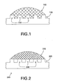
- Figure 1 demonstrates the situation where a drop 100 has struck a surface 120 having features 130 that make up a texture on surface 120, where the pressure associated with the surface 120 to resist wetting is much lower than the pressure exerted by drop 100 at impact.
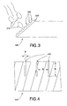
- drop 100 is able to penetrate into the spaces between features 130 and to wet a significant portion of the surface area of textured surface 120. This extensive contact serves to pin drop 100 to surface 120, which can lead to undesirable results such as icing, fouling, etc. Contrast this situation with that depicted in Figure 2, where the pressure generated by surface 200 is comparable to, or higher than, the pressure generated by drop 220 upon impact.
- the drop is unable to penetrate into the spaces between features 230, and only contacts the tops of features 230.
- the comparatively low contact area relative to the Figure 1 scenario suggests that removal of drop 220 from surface 200 will be desirably easier than removing drop 100 from surface 120. This ease of removal may promote shedding of the drop 220 from the surface 200 prior to freezing of the drop 220, thereby reducing or preventing the accumulation of ice, for example; or in another example, the drop 220 is shed prior to agglomeration with one or more other drops on the surface 200, maintaining a low mean drop size in a steam turbine fluid path and reducing the erosive effect of droplet impingement on turbine blades.
- a drop of liquid impacting a textured surface exerts pressure on the surface, and this pressure tends to promote drop wetting.
- the magnitude and nature of this pressure is time dependent.
- the pressure exerted is primarily due to the so-called "water hammer pressure,” which is proportional to the product of the velocity of the drop and the velocity of sound in the liquid medium.
- the pressure exerted by the drop is primarily due to the Bernoulli pressure of the drop, which is proportional to the square of the velocity of the drop. It will be appreciated that the water hammer pressure is generally much higher than the Bernoulli pressure.
- the textured surface upon which the drop strikes causes generation of pressure (also referred to herein as "back pressure") on the drop, and this back pressure tends to resist drop wetting.
- the back pressure may have one or multiple components.
- Capillary pressure exists because there is an energy barrier associated with wetting progressively larger quantities of a surface area. Because capillary pressure depends on the extent of interaction between fluid and surfaces, it is typically a function in part of the geometry of the system.
- the capillary pressure may thus be predicted by carefully describing the geometry of the surface texture and incorporating this description into the force balance analysis used to derive the capillary pressure equation.
- the geometry of a surface may be designed to provide a predicted capillary pressure of a desired value.
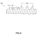
- an article 300 ( Figure 3) resistant to wetting by liquid droplets 310 impinging upon the article 300 thus comprises a surface portion 320 oriented to intercept the droplets 310, and this surface portion 320 comprises a plurality of surface features 330 designed to facilitate the generation of a back pressure that is equal to or greater than the wetting-promoting pressure generated by an impacting drop 310.
- a surface "oriented" to intercept droplets is not limited to a surface oriented normal to droplet motion relative to the surface; an interception of a droplet at any angle of impact is contemplated in various embodiments of the present invention.
- the wetting-promoting pressure is time-dependent and comprises water hammer pressure and/or Bernoulli pressure, depending on the time elapsed after drop impact.
- water hammer pressure which generally is greater than the Bernoulli pressure, as described above
- the drop is expected to be completely repelled from the spaces between the surface features making up the texture, and the drop will simply contact the top of the surface features as depicted in Figure 2.
- the configuration of the surface features 330 is selected to generate, in response to a droplet of liquid 310 impinging on the surface portion 320 at a relative velocity ( v ), a back pressure that is greater than a Bernoulli pressure generated by the droplet 310 upon impact on the surface portion 320.
- Surface feature 330 configuration may be selected to generate the appropriate level of back pressure based on knowledge of the above analysis (which determines the back pressure generated in response to drop impact), coupled with a knowledge of the expected value of droplet velocity and other droplet parameters for a given application (which determines the Bernoulli pressure of the drop).
- the mean velocity of water droplets and other drop parameters such as size may be known based on the nominal operating conditions of the turbine.
- This mean velocity may be used as v in the above analysis to calculate an expected value for the Bernoulli pressure of the droplets impinging upon components of the turbine, and, employing the above analysis, a configuration of surface features 330 may be designed for a surface portion 320 of the component article 300 where the back pressure generated upon impact of these drops meets or exceeds the Bernoulli pressure exerted by the drops.
- the surface features 330 may be elevations, such as cylindrical posts, rectangular prisms, pyramidal prisms, dendrites, nanorods, nanotubes, particle fragments, abrasion marks, or any other protrusion above the surface of the article 300.
- features 330 may be depressions disposed to some depth below the surface, such as holes, wells, and the like.
- the term "pore” is used herein to denote all such open spaces disposed to some depth below the surface of an article; this term should not be construed to limit the type of feature according to the method or process that disposed the pore. For example, a hole drilled into a surface is considered a "pore" for the purposes of this description.
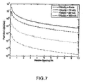
- surface portion 400 comprises a plurality of pores 410, and the plurality of pores 410 has a median pore size, a, a median pore depth, h, and a median pore spacing, b.
- the quantities a, b, and h are selected to generate back pressure in excess of an impacting droplet's Bernoulli pressure, as described more generally, above.
- a majority of the pores are isolated from each other; that is, there is little to no interconnection among pores.
- substantially all of the pores in the plurality are isolated from each other. Isolated pores, which have comparatively less volume than networks of connected pores, may facilitate the exertion of increased back pressure due to the rapid compression of vapor trapped inside the pore 410, as described above.
- Various configuration parameters may be defined to describe the configuration of the plurality of pores 410. These parameters, and the selected ranges defined herein, have been chosen based on the analysis set forth above.
- a parameter found to be of high significance in the generation of back pressure is the pore size, a.
- the magnitude of the back pressure generated upon drop impact is reduced as a is increased, and so pores having relatively large pore sizes may be selected for use in applications where drop impact velocity is expected to be relatively low, while smaller pore sizes may be selected for applications where impact velocities are expected to be high.
- Figure 5 illustrates the effect of pore size on the ability of a pore to facilitate the generation of back pressure.
- the inherent wettability that is, the wettability of an untextured, smooth surface
- droplet impact was assumed to occur for drops traveling in a line perpendicular to the surface. It should be noted here and throughout that assuming perpendicular (normal) impact results in a conservative design, as normal impact is the worst-case scenario with respect to pressure exerted by the drop on the surface. Impacts occurring at different angles than right angles with the surface result in a lower pressure being exerted by the drop.
- the plotted curve denotes values for pore radius (i.e., a /2) and drop velocity, where the Bernoulli pressure of the drop is expected to equal the back pressure generated at impact, taking into account both the capillary pressure and the resistance due to gas compression within the pore.
- the pressure resulting due to the gas compression in the pores was calculated using a penetration depth of three-quarters of the pore height. This depth was chosen to illustrate the effect of gas compression pressure. Pore sizes in the regions of the plot that fall beneath the curve are expected to provide very good resistance to drop wetting, while significant wetting is expected for situations above the curve. It will be apparent to those skilled in the art that embodiments of the present invention include any point that resides in the area on or beneath the curve shown in Figure 5.
- a is up to about 100 micrometers, such as up to 10 micrometers or up to 1 micrometer; these values of a, according to Figure 5, are expected to provide suitable back pressure for lower velocity applications, those where drop velocities are not expected to exceed about 40 m/s.
- a is up to about 100 nanometers (nm), which according to Figure 5 may provide suitable resistance to wetting for drop velocities up to about 60 m/s.
- a is up to about 20 nm. It will be appreciated that a is intended to have some non-zero value, but that very small values of a, as low as 1 nm or even less if practicable, are desirable to provide the highest levels of wetting resistance in very high velocity applications.
- Another parameter of interest in these embodiments is the aspect ratio of the pores, defined by the ratio h / a.
- aspect ratio appears to have little effect on the generation of back pressure.
- this ratio is significant where the surface may be subject to erosive or mechanical wear over time.
- a suitably high h / a is desirable to ensure that the pores will persist in spite of wear at the surface.
- the thickness of surface portion 400, and thus h, are selected based on the expected rate of wear and the desired useful lifetime of surface portion 400.
- the relative pore spacing may also be a parameter of interest in certain embodiments. Generally, as b / a decreases, the number of pores increases and the amount of solid surface available for the impinging drops to cling to decreases. Therefore, comparatively low relative pore spacings may facilitate fast roll-off of the impinging liquid, reduced ice adhesion, or both, due to the lower available surface contact area. In some embodiments, b / a is up to about 10. Where even further enhancements in roll-off promotion, ice adhesion reduction, or both, are desirable, this ratio is up to about 6, and in particular embodiments b / a is up to about 4.
- more than one parameter may be constrained in any combination of the embodiments described above.
- a is up to about 10 micrometers, and the ratio of b / a is up to about 4; while in other embodiments a is up to about 10 micrometers, and the ratio of b / a is up to about 6.
- article 420 comprises a component of an aircraft, such as, for example, a wing, tail, fuselage, or an aircraft engine component.
- article 420 is a component of a turbine assembly, such as a wind turbine assembly, a gas turbine assembly, or a steam turbine assembly.
- Non-limiting examples of aircraft engine components that are suitable as articles in embodiments of the present invention include the nacelle inlet lip, splitter leading edge, booster inlet guide vanes, fan outlet guide vanes, sensors and/or their shields, and fan blades. Certain components, such as fan blades, while sometimes made of metal, are often made of carbon-based composite materials.
- surface portion 400 may be a thin metallic foil attached to the composite, where features, such as the pores 410 described above, are disposed on the foil.
- features 410 may be disposed directly onto the composite article via a coating method as described above, or the composite article itself may be machined or otherwise formed to have integral features at its surface.
- article 420 is a component, such as a turbine blade, anemometer, gearbox, or other component, of a wind turbine assembly.
- Features 410 may be disposed on such components in a manner similar to that described above for composite fan blades in jet engines.
- article 420 As other components exposed to the weather are also adversely affected by ice and/or water accumulation, other embodiments of article 420 include, for instance, components of other items exposed to the weather, such as power lines, antennas, and solar cells. The ability to resist wetting by impacting precipitation may benefit a host of components that are so exposed, and the examples presented herein should not be read as limiting embodiments of the present invention to only those named applications.
- article 420 is a component of a turbine assembly, such as a wind turbine assembly, a gas turbine assembly, or a steam turbine assembly.
- Suitable components for gas and/or steam turbine assembly applications include a turbine blade, a low-pressure steam turbine blade, a high-pressure steam turbine blade, a compressor blade, a condenser, and a stator component.
- surface portion 500 comprises a plurality of elevations 510, and the plurality of elevations 510 has a median size, a ; a median height, h ; and a median spacing, b.
- the quantities a, b, and h are selected to generate, in response to a droplet of the liquid having a droplet size of at least about 1 micrometer impinging upon the surface portion at a relative velocity of at least 5 meters per second, a back pressure that is greater than a Bernoulli pressure generated by the drop upon impact on the surface portion.
- the drop size is at least about 10 micrometers
- the velocity is at least about 50 meters per second.
- the ability to resist wetting by drops of this size and having this speed may enable surface portion 510 to be used in applications such as wind turbine assembly components, aircraft components, and other components exposed to the weather, as described above, where resistance to icing and the ability quickly to shed droplets of liquid are desirable characteristics.
- certain ranges for certain feature configuration parameters may be particularly effective in resisting wetting under these conditions.
- the surface features are pores
- the relative feature spacing b / a significantly affects back pressure.
- a reduction in b / a generally results in a higher back pressure, but at the same time the surface area available for drop contact becomes increased.
- a tradeoff thus may exist between the need for high back pressure and the need to reduce drop adhesion to the surface.
- Figure 7 illustrates the effect of relative feature spacing and feature size on the generation of back pressure. As shown in this figure, the effect is also a function of the velocity of the incoming drop, in contrast to embodiments employing pores, described above.
- surface feature designs characterized by size and relative spacing lying below the curve plotted for a given drop velocity are expected to provide significant wetting resistance for drops having that given velocity.
- the effective "design space" denoted by the area under the curve becomes smaller as the expected velocity becomes higher, pushing the allowable feature sizes to lower values and reducing the allowable spacing.
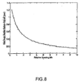
- Figure 8 illustrates the effect of relative spacing ( b / a ) on roll-off behavior.
- the drop size prior to roll-off of a vertical surface is plotted against b / a, and clearly roll-off is facilitated more easily at comparatively high relative spacing values.
- the feature aspect ratio, h / a can play an important role in the wetting resistance of the surface from the consideration of the kinetics of droplet penetration into the texture.
- the effect is still relatively small compared to the effects for size and relative spacing as described above. Again, a significant consideration in selecting h in these embodiments the expected wear rate and the desired life of the surface portion 510.
- Elevation feature parameters are thus selected while taking the tradeoff described above and the effects of wear into consideration.
- a is up to about 300 micrometers, and b / a is up to about 10.
- a is up to about 50 micrometers, and b / a is up to about 10.
- the plurality of elevations 510 comprises an ordered (that is, a non-random) array disposed on surface portion 500, though random distributions of features 510 may be effective under certain circumstances.
- Ordered arrays in some embodiments, comprise features such as cylindrical posts, rectangular prisms, and pyramidal prisms. Random distributions may comprise these features, and in some embodiments they may comprise such features as dendrites, nanorods, nanotubes, particle fragments, and abrasion marks. It should be noted that whether the plurality of features 510 is randomly or non-randomly distributed has no bearing on the specific type of feature or features making up the plurality.
- Component 600 comprises a surface portion 610 oriented to intercept incoming droplets 620 of a liquid entrained in a fluid flow path 630 of the steam turbine assembly.
- Surface portion 610 comprises a plurality of elevations 640, and this plurality has a median feature size, a ; a median feature height, h ; and a median feature spacing, b as these parameters are depicted in Figure 6.
- a, b , and h are selected to generate, in response to a droplet 620 of the liquid impinging upon the surface portion 610 at a relative velocity v, a back pressure that is greater than a Bernoulli pressure generated by the drop upon impact on the surface portion.
- the distribution and shape of elevations 640 in this embodiment are the same as those described for the embodiment depicted in Figure 6.
- a is up to about 5 micrometers
- b / a is up to about 10.
- FIG. 3 Further embodiments of the present invention include a method for resisting wetting of an article 300 ( Figure 3) by impinging droplets 310 of liquid.
- the method comprises providing article 300 with a surface portion 320 that is oriented to intercept incoming droplets 310 of liquid.
- Surface portion 320 comprises a plurality of features 330 so disposed on the surface portion 320 to generate, in response to a drop of liquid impinging upon surface portion 320 at a relative velocity within a given relative velocity range, a back pressure that is greater than the wetting-promoting pressure, such as, for example, the Bernoulli pressure, generated by an impacting drop 310.
- the surface portion 320 is then exposed to droplets 310 of liquid moving at relative velocities within the given relative velocity range so that the droplets 310 impinge upon surface portion 320.
- the relative velocity range is encompasses velocities of at least about 5 m/s.
- features 310 may be characterized by parameters such as a median size, a, a median height displacement, h , and a median spacing, b .
- the method described above further comprises specifying a back pressure minimum requirement based on expected operating conditions for the article; calculating back pressure as a function of the feature characterization parameters (for example, a, b, h ); and selecting appropriate values of these parameters so that the surface portion 320 is expected to generate a back pressure greater than or equal to the back pressure minimum requirement.
- the calculation of back pressure as a function of pore size shown in Figure 5 specifies a median pore size of up to about 100 nm.
- the article would be provided with pores having a median pore size of up to about 100 nm.
- surface portion 320 and features 330 are common across the various embodiments described above, regardless of the type of surface features 330 being used.
- surface portion 320 comprises a ceramic, a metal, a semi-metal, or a polymer.
- surface portion 320 comprises a porous material, such as, for example, an anodized metal oxide.
- Anodized aluminum oxide is a particular example of a porous material that may be suitable for use in some embodiments.
- Anodized aluminum oxide typically comprises columnar pores, and pore parameters such as diameter and aspect ratio may be closely controlled by the anodization process.
- service conditions are conducive to the use of polymeric coatings, fluorinated materials, and other traditional low-wettability materials.
- these materials may be applied to surface portion 320 to provide enhanced resistance to wetting.
- many applications including, for instance, certain medical devices, heat exchangers, aircraft components, and turbomachinery such as aircraft engines, which would benefit from the use of articles having low wettability in accordance with embodiments of the present invention, are subject to harsh chemical, thermal, and/or tribological conditions that preclude the use of traditional polymer-based low-wettability materials and coatings.
- the surface portion 320 and its features 330 are free of any polymeric coatings; in some embodiments, they consist essentially of metallic, intermetallic, semi-metallic, or ceramic materials.
- features 330 comprise a material selected from the group consisting of a metal, an intermetallic compound, and a semi-metal. Although these materials have moderate to high inherent wettability for many important liquids, such as water and oil, altering article surfaces in accordance with embodiments of the present invention may significantly reduce the wettability of articles made from such materials.
- suitable metals from which surface portion 320 and features 330 can be made include, but are not limited to, aluminum, copper, iron, nickel, cobalt, gold, platinum, titanium, zinc, tin, and alloys comprising at least one of these elements, such as steel, high-temperature superalloys, and aluminum alloys.
- intermetallic compounds include, but are not limited to, compounds containing at least one of the elements listed above, such as aluminides and silicides. Silicon is one non-limiting example of a suitable semi-metal.
- surface portion 320 comprises the same material as the features 130.
- surface portion 320 and features 330 are integral and, in particular embodiments, comprise the same metal composition.
- Metals, ceramics, semi-metals, and intermetallic materials generally have moderate to high wettability, and thus the effect of surface texturing by providing features 330 as described herein may not always suffice to provide desired levels of wettability, absent some means of lowering the inherent wettability of the features 330.
- the inherent wettability of the material used for surface portion 320 that will actually contact the liquid in some embodiments, is sufficiently low to generate, with a static drop of the liquid, a contact angle of at least about 70 degrees; in some embodiments this angle is at least about 90 degrees, and in particular embodiments, the angle is at least about 110 degrees.
- surface portion 320 further comprises a surface energy modification material (not shown).
- This material is formed, in one embodiment, by overlaying a layer of material at surface portion 320, resulting in a coating disposed over features 330.
- Hydrophobic hardcoatings are one suitable option.
- Diamond-like carbon (DLC) coatings which typically have high wear resistance, have been applied to metallic articles to improve resistance to wetting (see, for example, US6623241 ).
- Other hard coatings such as nitrides or oxides, such as tantalum oxide, may also serve this purpose. These hardcoatings, and methods for applying them (CVD, PVD, etc.), are known in the art, and may be of particular use in harsh environments.
- Fluorinated materials such as fluorosilanes
- coating materials that exhibit low wettability for certain liquids, including water.
- the coating may comprise a polymeric material.
- polymeric materials known to have advantageous resistance to wetting by certain liquids include silicones, fluoropolymers, urethanes, acrylates, epoxies, polysilazanes, aliphatic hydrocarbons, polyimides, polycarbonates, polyether imides, polystyrenes, polyolefins, polypropylenes, polyethylenes or mixtures thereof.
- the surface modification layer may be formed by diffusing or implanting molecular, atomic, or ionic species into the surface portion 320 to form a layer of material having altered surface properties compared to material underneath the surface modification layer.
- the surface energy modifying material comprises ion-implanted material, for example, ion-implanted metal. Ion implantation of metallic materials with ions of boron (B), nitrogen (N), fluorine (F), carbon (C), oxygen (O), helium (He), argon (Ar), or hydrogen (H) may lower the surface energy (and hence the wettability) of the implanted material. See, for example, A.
- a diffusion hardening processes such as a nitriding process or a carburizing process is used to dispose the surface modification material, and thus the surface modification material comprises a nitrided material or a carburized material.
- Nitriding and carburizing processes are known in the art to harden the surface of metals by diffusing nitrogen or carbon into the surface of the metal and allowing strong nitride-forming or carbide-forming elements contained within the metal to react to form a layer of nitride material or a dispersion of nitride particles, depending on the metal composition and processing parameters.
- nitriding processes usually take place in a temperature range of about 500°C - 550°C.
- Nitriding processes known in the art include ion nitriding, gas nitriding, and salt-bath nitriding, so named based upon the state of the nitrogen source used in the process. These processes have shown a remarkable potential for lowering metal surface energy.
- the contact angle (measured using water as reference liquid) of 403 steel having a surface finish of 32 microinches was increased from about 60 degrees to about 115 degrees by ion nitriding.
- a preliminary observation of the surface of the nitrided surface applied to mirror-finish specimens ( ⁇ 2 microinches) suggests that the nitriding process may deposit nano-scale features at the surface in addition to reducing the inherent surface energy of the metal.
- the surface modification layer may be applied after features 330 have been provided on surface portion 320.
- features 330 may be formed after applying surface modification layer to surface portion 320. The choice of order will depend on the particular processing methods being employed and the materials being used for features 330 and surface portion 320.
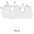
- At least one feature 800 comprises a plurality of secondary features 810 disposed on the feature 800.
- the example depicted in Figure 10 shows an ordered array of identical secondary features 810, such an arrangement is not a general requirement; random arrangements and other distributions in size, shape, and orientation may be appropriate for specific applications.
- Secondary features 810 may be characterized by a height dimension h' referenced to a feature baseline plane 820 (whether the secondary feature protrudes above plane 820 or is a pore disposed in feature 800 to a depth h' below plane 820), a width dimension a', and a spacing dimension b', all parameters defined analogously to a, b, and h described above.
- the parameters a', b', and h' will often be selected based on the conditions particular to the desired application. In some embodiments a', b', and h' are all within the range from about 1 nm to about 1000nm.
- pores 900 are cavity features disposed on surface portion 910.
- pore walls 915 comprise secondary features 920 disposed at pore walls 915.
- Secondary features 920 may be structures protruding above pore walls 915 or depressions disposed in the walls 915.
- the secondary features 920 have a characteristic dimension, such as, for example, the aforementioned height h', width a', or spacing b', of less than 1 micrometer.
- features 330 can be fabricated and provided to article 300 by a number of methods.
- features 330 are fabricated directly on surface portion 320 of article 300.
- features 330 are fabricated separately and then disposed onto article 300 at surface portion 320.
- Disposition of features 330 onto article 300 can be done by individually attaching features 330, or the features 330 may be disposed on a sheet, foil or other suitable medium that is then attached to article 300. Attachment in either case may be accomplished through any appropriate method, such as, but not limited to, welding, brazing, mechanically attaching, or adhesively attaching via epoxy or other adhesive.
- the disposition of features 330 may be accomplished by disposing material onto the surface of the article, by removing material from the surface, or a combination of both depositing and removing.
- Many methods are known in the art for adding or removing material from a surface. For example, simple roughening of the surface by mechanical operations such as grinding, grit blasting, or shot peening may be suitable if appropriate media/tooling and surface materials are selected. Such operations will generally result in a distribution of randomly oriented features on the surface, while the size-scale of the features will depend significantly on the size of the media and/or tooling used for the material removal operation. Lithographic methods are commonly used to create surface features on etchable surfaces, including metal surfaces.
- Ordered arrays of features can be provided by these methods easily; the lower limit of feature size available through these techniques is limited by the resolution of the particular lithographic process being applied.
- electroplating methods are also commonly used to add features to surfaces.
- An electrically conductive surface may be masked in a patterned array to expose areas upon which features are to be disposed, and the features may be built up on these exposed regions by plating. This method allows the creation of features having higher aspect ratios than those commonly achieved by etching techniques.
- the masking is accomplished by the use of an anodized aluminum oxide (AAO) template having a well-controlled pore size.
- AAO anodized aluminum oxide
- Nanorods of metal and metal oxides may be deposited using commonly known processing, and these materials may be further processed (by carburization, for example) to form various ceramic materials such as carbides. Coatings may be applied to the features to provide even better wettability properties as described above.
- Micromachining techniques such as laser micromachining (commonly used for silicon and stainless steels, for example) and etching techniques (commonly used for silicon) are suitable methods as well. Such techniques may be used to form cavities (as in laser drilling) as well as protruding features. In short, any of a number of deposition processes or material removal processes commonly known in the art may be used to apply features to a surface. As described above, the features may be applied directly onto article 300, or applied to a substrate that is then attached to article 300.
- Example 1 Three specimens having unique textured surfaces were fabricated from silicon using standard photolithography techniques followed by deep reactive ion etching. Specimen A had rectangular prism post features of width 15 micrometers and spacing 150 micrometers. Specimen B had rectangular prism post features of width 15 micrometers and spacing 5 micrometers. Specimen C had rectangular prism post features of width 3 micrometers, spacing 30 micrometers, and further had silicon-rich dendrites attached to the posts as secondary features (described above).
- the dendrites were spaced apart by a mean distance of about 100 nm, and were grown on the posts by preferential etching and re-deposition during the reactive ion etching process.
- Each specimen was coated with tridecafluoro-1,1,2,2-tetrahydrooctyl-trichlorosilane (hereinafter "fluorosilane”) via vapor deposition
- fluorosilane tridecafluoro-1,1,2,2-tetrahydrooctyl-trichlorosilane
- the droplet therefore had a water hammer pressure of about 1500 kiloPascals (kPa) and a Bernoulli pressure of about 5 kPa at impact, and specimens A, B, and C were expected to generate respective back pressures of about 0.08 kPa, 12 kPa, and 1200 kPa based on their feature size, shape, and spacing.
- the impacting droplets initially exhibited similar spreading behavior immediately following impact, but subsequently exhibited strikingly different retracting behavior.
- the droplet impacting specimen A did not retract appreciably and maintained substantial contact with the specimen.
- the droplet impacting specimen B retracted nearly entirely, maintaining only a contact area that was a small fraction of the diameter of the pre-impact droplet.
- Example 2 Specimen B was also subject to impact by droplets with 350 micrometer diameters moving at 10 m/s relative to the specimen. Droplets therefore had a water hammer pressure of about 5,000 kPa and a Bernoulli pressure of about 50 kPa. As described in Example 1, Specimen B is expected to provide 1,200 kPa of back pressure. Impacting droplets retracted nearly entirely.
- Example 3 A specimen of silicon coated with carbon nanotube (CNT) nanostructures was fabricated by a chemical vapor deposition process, using ethylene and methane as carbon sources and a 4-to-1 nickel-iron alloy as a catalyst.
- CNT carbon nanotube
- Example 2 This specimen was then coated with fluorosilane via vapor deposition as in Example 1. CNT diameters were roughly 100 nanometers, but because CNTs coil and are arrayed randomly, an average effective spacing is difficult to estimate.
- the specimen was subject to impact by droplets moving at 3 m/s and 10 m/s, similar to those in Examples 1 and 2, respectively. Droplets moving at 3 m/s retracted completely, while those moving at 10 m/s retracted nearly entirely.
- Example 4 A specimen of nanoporous aluminum oxide was fabricated by immersing aluminum-coated silicon in a 0.3-molar solution of oxalic acid at room temperature (constant 40 volts DC for 6min), yielding a porous anodized aluminum oxide (AAO) layer about 1 micrometer in thickness. These pores were then widened with a solution of 0.2-molar phosphoric acid at room temperature for 120min to yield an average pore size of about 90 nanometers that have a typical edge-to-edge spacing of about 10 nanometers. This specimen was then coated with fluorosilane via vapor deposition as in Example 1. The specimen was subject to impact by droplets moving at 10 m/s and 20 m/s.
- AAO anodized aluminum oxide
- Droplets therefore had water hammer pressures of about 5,000 and 10,000 kPa and Bernoulli pressures of about 50 and 200 kPa, respectively. This specimen is expected to provide a back pressure of about 1,000 kPa, based on the feature size and shape. All droplets moving at 20 m/s retracted nearly entirely. Droplets moving at 10 m/s exhibited mixed behavior: some drops showed similar to the 20 m/s droplets, while others retracted completely.
- Example 5 A vane from a CF6 aircraft engine (stage 1) was coated with CNTs using the parameters discussed in Example 3. The leading edge of the vane was subjected to impact by 1-millimeter radius droplets moving about 3 m/s.
- Example 6 A pipe composed of 6061 aluminum with a diameter of about one inch was first polished with fine sandpaper and then coated with AAO via an anodization process similar to the one described in Example 4. This curved surface was subjected to impact by 1-millimeter radius droplets moving about 3 m/s. Droplets retracted completely.
Landscapes
- Engineering & Computer Science (AREA)
- Mechanical Engineering (AREA)
- General Engineering & Computer Science (AREA)
- Chemical & Material Sciences (AREA)
- Materials Engineering (AREA)
- Physics & Mathematics (AREA)
- Fluid Mechanics (AREA)
- Turbine Rotor Nozzle Sealing (AREA)
- Physical Or Chemical Processes And Apparatus (AREA)
- Perforating, Stamping-Out Or Severing By Means Other Than Cutting (AREA)
- Application Of Or Painting With Fluid Materials (AREA)
- Silicon Compounds (AREA)
Applications Claiming Priority (2)
| Application Number | Priority Date | Filing Date | Title |
|---|---|---|---|
| US70523905P | 2005-08-03 | 2005-08-03 | |
| US48702306A | 2006-07-17 | 2006-07-17 |
Publications (2)
| Publication Number | Publication Date |
|---|---|
| EP1750018A2 true EP1750018A2 (fr) | 2007-02-07 |
| EP1750018A3 EP1750018A3 (fr) | 2011-12-14 |
Family
ID=37310749
Family Applications (1)
| Application Number | Title | Priority Date | Filing Date |
|---|---|---|---|
| EP06254002A Withdrawn EP1750018A3 (fr) | 2005-08-03 | 2006-07-31 | Surfaces et articles resistants à l'impacte de liquides |
Country Status (2)
| Country | Link |
|---|---|
| EP (1) | EP1750018A3 (fr) |
| JP (1) | JP2007130747A (fr) |
Cited By (16)
| Publication number | Priority date | Publication date | Assignee | Title |
|---|---|---|---|---|
| EP2251482A1 (fr) * | 2009-05-14 | 2010-11-17 | Koninklijke Philips Electronics N.V. | Unité de décharge de vapeur pour une utilisation dans la semelle d'un fer à repasser |
| EP2343400A1 (fr) * | 2009-12-22 | 2011-07-13 | Rolls-Royce plc | Surface hydrophobe |
| WO2011147416A3 (fr) * | 2010-05-26 | 2012-03-22 | Vestas Wind Systems A/S | Composant de turbine éolienne comprenant une couche de surface pour empêcher l'adhésion de glace |
| EP2256452A4 (fr) * | 2008-03-24 | 2013-07-31 | Mitsubishi Electric Corp | Échangeur de chaleur et dispositif à cycle de réfrigération le comportant |
| EP2472064A3 (fr) * | 2010-12-30 | 2013-10-30 | Rolls-Royce Corporation | Aube pour moteur de turbine à gaz |
| RU2547829C2 (ru) * | 2010-05-07 | 2015-04-10 | Айсис Инновейшен Лимитед | Способ и устройство создания локализованной концентрации энергии |
| RU2554094C2 (ru) * | 2009-11-27 | 2015-06-27 | Айсис Инновейшен Лимитед | Способ и устройство для фокусировки энергии |
| DE102014215082A1 (de) * | 2014-07-31 | 2016-02-04 | Siemens Aktiengesellschaft | Laufschaufel für eine Dampfturbine |
| WO2016147190A1 (fr) * | 2015-03-19 | 2016-09-22 | Palram Industries (1990) Ltd. | Surface autonettoyante et procédé de formation de cette dernière |
| BE1024829B1 (fr) * | 2016-12-15 | 2018-07-17 | Safran Aero Boosters S.A. | Aube rugueuse pour compresseur de turbomachine axiale |
| EP3916135A1 (fr) * | 2020-05-26 | 2021-12-01 | Airbus (S.A.S.) | Procédé de modification d'une surface métallique, telle qu'une partie de bord d'attaque d'une surface portante |
| US11492500B2 (en) | 2012-11-19 | 2022-11-08 | Massachusetts Institute Of Technology | Apparatus and methods employing liquid-impregnated surfaces |
| WO2023012214A1 (fr) * | 2021-08-05 | 2023-02-09 | Irt Antoine De Saint Exupéry | Article pour une application antigivre |
| US11933551B2 (en) * | 2011-08-05 | 2024-03-19 | Massachusetts Institute Of Technology | Liquid-impregnated surfaces, methods of making, and devices incorporating the same |
| US12005161B2 (en) | 2012-05-24 | 2024-06-11 | Massachusetts Institute Of Technology | Medical devices and implements with liquid-impregnated surfaces |
| US12103051B2 (en) | 2012-11-19 | 2024-10-01 | Massachusetts Institute Of Technology | Apparatus and methods employing liquid-impregnated surfaces |
Families Citing this family (8)
| Publication number | Priority date | Publication date | Assignee | Title |
|---|---|---|---|---|
| US7892660B2 (en) * | 2007-12-18 | 2011-02-22 | General Electric Company | Wetting resistant materials and articles made therewith |
| US8245981B2 (en) * | 2008-04-30 | 2012-08-21 | General Electric Company | Ice shed reduction for leading edge structures |
| JP2010175131A (ja) * | 2009-01-29 | 2010-08-12 | Mitsubishi Electric Corp | 熱交換装置、冷凍・空調装置、熱交換器製造方法 |
| CA2847545A1 (fr) * | 2011-08-03 | 2013-02-07 | Massachusetts Institute Of Technology | Articles destines a la manipulation de liquides d'impact et leurs procedes de fabrication |
| US8945254B2 (en) * | 2011-12-21 | 2015-02-03 | General Electric Company | Gas turbine engine particle separator |
| JP6331222B2 (ja) * | 2013-09-26 | 2018-05-30 | Toto株式会社 | 水まわり用金属部材 |
| JP6600809B2 (ja) * | 2015-07-07 | 2019-11-06 | パナソニックIpマネジメント株式会社 | 基材およびその基材を用いた機器 |
| KR102632739B1 (ko) * | 2022-01-27 | 2024-02-01 | 가천대학교 산학협력단 | 마이크로 채널 및 이를 포함하는 표면체 |
Citations (1)
| Publication number | Priority date | Publication date | Assignee | Title |
|---|---|---|---|---|
| US6623241B2 (en) | 2000-11-14 | 2003-09-23 | Alstom (Switzerland) Ltd | Low-pressure steam turbine |
Family Cites Families (5)
| Publication number | Priority date | Publication date | Assignee | Title |
|---|---|---|---|---|
| US3354022A (en) * | 1964-03-31 | 1967-11-21 | Du Pont | Water-repellant surface |
| AU2640099A (en) * | 1999-02-25 | 2000-09-14 | Seiko Epson Corporation | Structure member excellent in water-repellency and manufacturing method thereof |
| EP1186749A1 (fr) * | 2000-09-07 | 2002-03-13 | Siemens Aktiengesellschaft | Turbomachine et aube de turbine |
| JP4315717B2 (ja) * | 2003-03-24 | 2009-08-19 | 財団法人神奈川科学技術アカデミー | 金属モールド及びその製造方法並びに陽極酸化ポーラスアルミナとその製造方法 |
| US6852390B2 (en) * | 2003-04-15 | 2005-02-08 | Entegris, Inc. | Ultraphobic surface for high pressure liquids |
-
2006
- 2006-07-31 EP EP06254002A patent/EP1750018A3/fr not_active Withdrawn
- 2006-08-02 JP JP2006210635A patent/JP2007130747A/ja active Pending
Patent Citations (1)
| Publication number | Priority date | Publication date | Assignee | Title |
|---|---|---|---|---|
| US6623241B2 (en) | 2000-11-14 | 2003-09-23 | Alstom (Switzerland) Ltd | Low-pressure steam turbine |
Non-Patent Citations (2)
| Title |
|---|
| A. LEIPERTZ, DROPWISE CONDENSATION HEAT TRANSFER ON ION IMPLANTED METALLIC SURFACES, Retrieved from the Internet <URL:http://www.ltt.uni-erlangen.de/inhalt/pdfs/tk_gren.pdf> |
| XUEHU MA: "Advances in Dropwise Condensation Heat Transfer: Chinese Research", CHEMICAL ENGINEERING JOURNAL, vol. 78, 2000, pages 87 - 93 |
Cited By (20)
| Publication number | Priority date | Publication date | Assignee | Title |
|---|---|---|---|---|
| EP2256452A4 (fr) * | 2008-03-24 | 2013-07-31 | Mitsubishi Electric Corp | Échangeur de chaleur et dispositif à cycle de réfrigération le comportant |
| WO2010131148A1 (fr) * | 2009-05-14 | 2010-11-18 | Koninklijke Philips Electronics N.V. | Unité de décharge de vapeur pour utilisation dans une semelle d'un fer à vapeur |
| EP2251482A1 (fr) * | 2009-05-14 | 2010-11-17 | Koninklijke Philips Electronics N.V. | Unité de décharge de vapeur pour une utilisation dans la semelle d'un fer à repasser |
| US8615909B2 (en) | 2009-05-14 | 2013-12-31 | Koninklijke Philips N.V. | Steam discharge unit for use in a soleplate of a steam iron |
| RU2554094C2 (ru) * | 2009-11-27 | 2015-06-27 | Айсис Инновейшен Лимитед | Способ и устройство для фокусировки энергии |
| EP2343400A1 (fr) * | 2009-12-22 | 2011-07-13 | Rolls-Royce plc | Surface hydrophobe |
| RU2547829C2 (ru) * | 2010-05-07 | 2015-04-10 | Айсис Инновейшен Лимитед | Способ и устройство создания локализованной концентрации энергии |
| WO2011147416A3 (fr) * | 2010-05-26 | 2012-03-22 | Vestas Wind Systems A/S | Composant de turbine éolienne comprenant une couche de surface pour empêcher l'adhésion de glace |
| EP2472064A3 (fr) * | 2010-12-30 | 2013-10-30 | Rolls-Royce Corporation | Aube pour moteur de turbine à gaz |
| US11933551B2 (en) * | 2011-08-05 | 2024-03-19 | Massachusetts Institute Of Technology | Liquid-impregnated surfaces, methods of making, and devices incorporating the same |
| US12005161B2 (en) | 2012-05-24 | 2024-06-11 | Massachusetts Institute Of Technology | Medical devices and implements with liquid-impregnated surfaces |
| US12103051B2 (en) | 2012-11-19 | 2024-10-01 | Massachusetts Institute Of Technology | Apparatus and methods employing liquid-impregnated surfaces |
| US11492500B2 (en) | 2012-11-19 | 2022-11-08 | Massachusetts Institute Of Technology | Apparatus and methods employing liquid-impregnated surfaces |
| EP2985420A1 (fr) * | 2014-07-31 | 2016-02-17 | Siemens Aktiengesellschaft | Aube de turbine à vapeur |
| DE102014215082A1 (de) * | 2014-07-31 | 2016-02-04 | Siemens Aktiengesellschaft | Laufschaufel für eine Dampfturbine |
| WO2016147190A1 (fr) * | 2015-03-19 | 2016-09-22 | Palram Industries (1990) Ltd. | Surface autonettoyante et procédé de formation de cette dernière |
| BE1024829B1 (fr) * | 2016-12-15 | 2018-07-17 | Safran Aero Boosters S.A. | Aube rugueuse pour compresseur de turbomachine axiale |
| EP3916135A1 (fr) * | 2020-05-26 | 2021-12-01 | Airbus (S.A.S.) | Procédé de modification d'une surface métallique, telle qu'une partie de bord d'attaque d'une surface portante |
| WO2023012214A1 (fr) * | 2021-08-05 | 2023-02-09 | Irt Antoine De Saint Exupéry | Article pour une application antigivre |
| FR3125981A1 (fr) * | 2021-08-05 | 2023-02-10 | Irt Antoine De Saint Exupéry | Article pour une application antigivre |
Also Published As
| Publication number | Publication date |
|---|---|
| JP2007130747A (ja) | 2007-05-31 |
| EP1750018A3 (fr) | 2011-12-14 |
Similar Documents
| Publication | Publication Date | Title |
|---|---|---|
| EP1750018A2 (fr) | Surfaces et articles resistants à l'impacte de liquides | |
| US20070031639A1 (en) | Articles having low wettability and methods for making | |
| JP5143735B2 (ja) | 伝熱装置及び該装置を含むシステム | |
| EP1935509A1 (fr) | Articles dotés de surfaces antisalissure et leurs procédés de fabrication | |
| Talari et al. | Leidenfrost drops on micro/nanostructured surfaces | |
| Tian et al. | Superhard self-lubricating AlMgB 14 films for microelectromechanical devices | |
| Attinger et al. | Surface engineering for phase change heat transfer: A review | |
| US10814580B2 (en) | Erosion resistant and hydrophobic article | |
| EP2739410B1 (fr) | Article comprenant une surface imprégnée de liquide | |
| JP4092099B2 (ja) | 低圧蒸気タービン | |
| US8334031B2 (en) | Wetting resistant material and articles made therewith | |
| GB2568063B (en) | Water droplet erosion resistant coatings for turbine blades and other components | |
| EP2992288A1 (fr) | Revêtements fonctionnels améliorant l'efficacité de condenseur | |
| Zhu et al. | Air cushion storing energy promoting droplets retraction and flow on engineering porous bionic lotus surfaces | |
| Kuzma-Kichta et al. | Studying the wetting of a surface with combined structure | |
| EP3343164A1 (fr) | Revêtements fonctionnels, améliorant les performances de condenseur | |
| Khalid et al. | The effect of NI-TIO2 and NI-TIO2-graphene coatings and heat treatment hardening on solid particles erosion resistance of grade 410 stainless steel | |
| RU2795437C2 (ru) | Устойчивые к каплеударной эрозии покрытия для турбинных лопаток и других компонентов | |
| Attinger et al. | How to Engineer Surfaces to Control and Optimize Boiling, Condensation and Frost Formation? | |
| Cui et al. | Robust superhydrophobic Ti–6Al–4V surface via laser-electrodeposition with microstructure enhancement | |
| Rao et al. | Effect of surface configuration during solid particle impingement erosion | |
| Jang et al. | Effect of Improved Surface Wetability and Adhesion of Undulated Diamond-like Carbon Structure with rf PE-CVD | |
| CN120776294A (zh) | 一种强化低温预冷换热的复合微纳结构表面及加工方法 | |
| Ramanathana | Cecílio Alvares da Cunhaa, Olandir Vercino Correaa, Isaac Jamil Sayegb | |
| Peng et al. | The Heat Transfer Performance of the Superhydrophobic Surfaces with Wear Resistance |
Legal Events
| Date | Code | Title | Description |
|---|---|---|---|
| PUAI | Public reference made under article 153(3) epc to a published international application that has entered the european phase |
Free format text: ORIGINAL CODE: 0009012 |
|
| AK | Designated contracting states |
Kind code of ref document: A2 Designated state(s): AT BE BG CH CY CZ DE DK EE ES FI FR GB GR HU IE IS IT LI LT LU LV MC NL PL PT RO SE SI SK TR |
|
| AX | Request for extension of the european patent |
Extension state: AL BA HR MK YU |
|
| PUAL | Search report despatched |
Free format text: ORIGINAL CODE: 0009013 |
|
| AK | Designated contracting states |
Kind code of ref document: A3 Designated state(s): AT BE BG CH CY CZ DE DK EE ES FI FR GB GR HU IE IS IT LI LT LU LV MC NL PL PT RO SE SI SK TR |
|
| AX | Request for extension of the european patent |
Extension state: AL BA HR MK RS |
|
| RIC1 | Information provided on ipc code assigned before grant |
Ipc: F01D 5/28 20060101ALI20111108BHEP Ipc: F15D 1/06 20060101AFI20111108BHEP |
|
| 17P | Request for examination filed |
Effective date: 20120614 |
|
| 17Q | First examination report despatched |
Effective date: 20120713 |
|
| AKX | Designation fees paid |
Designated state(s): DE FR GB |
|
| STAA | Information on the status of an ep patent application or granted ep patent |
Free format text: STATUS: THE APPLICATION IS DEEMED TO BE WITHDRAWN |
|
| 18D | Application deemed to be withdrawn |
Effective date: 20130124 |