EP1750104A2 - Dispositif et procédé destinés à l'enregistrement d'un niveau seuil de remplissage à vibrations - Google Patents
Dispositif et procédé destinés à l'enregistrement d'un niveau seuil de remplissage à vibrations Download PDFInfo
- Publication number
- EP1750104A2 EP1750104A2 EP06010806A EP06010806A EP1750104A2 EP 1750104 A2 EP1750104 A2 EP 1750104A2 EP 06010806 A EP06010806 A EP 06010806A EP 06010806 A EP06010806 A EP 06010806A EP 1750104 A2 EP1750104 A2 EP 1750104A2
- Authority
- EP
- European Patent Office
- Prior art keywords
- vibration
- compensation
- piezoelectric element
- capacitance
- compensation capacitor
- Prior art date
- Legal status (The legal status is an assumption and is not a legal conclusion. Google has not performed a legal analysis and makes no representation as to the accuracy of the status listed.)
- Granted
Links
- 238000000034 method Methods 0.000 title claims abstract 10
- 239000003990 capacitor Substances 0.000 claims abstract 13
- 230000001419 dependent effect Effects 0.000 claims abstract 4
- 238000001514 detection method Methods 0.000 claims abstract 3
- 230000001105 regulatory effect Effects 0.000 claims 3
- 230000001360 synchronised effect Effects 0.000 claims 3
- 239000004020 conductor Substances 0.000 claims 1
- 238000010079 rubber tapping Methods 0.000 claims 1
- 230000005611 electricity Effects 0.000 abstract 1
Images


Classifications
-
- G—PHYSICS
- G01—MEASURING; TESTING
- G01F—MEASURING VOLUME, VOLUME FLOW, MASS FLOW OR LIQUID LEVEL; METERING BY VOLUME
- G01F23/00—Indicating or measuring liquid level or level of fluent solid material, e.g. indicating in terms of volume or indicating by means of an alarm
- G01F23/22—Indicating or measuring liquid level or level of fluent solid material, e.g. indicating in terms of volume or indicating by means of an alarm by measuring physical variables, other than linear dimensions, pressure or weight, dependent on the level to be measured, e.g. by difference of heat transfer of steam or water
- G01F23/28—Indicating or measuring liquid level or level of fluent solid material, e.g. indicating in terms of volume or indicating by means of an alarm by measuring physical variables, other than linear dimensions, pressure or weight, dependent on the level to be measured, e.g. by difference of heat transfer of steam or water by measuring the variations of parameters of electromagnetic or acoustic waves applied directly to the liquid or fluent solid material
- G01F23/296—Acoustic waves
- G01F23/2968—Transducers specially adapted for acoustic level indicators
-
- G—PHYSICS
- G01—MEASURING; TESTING
- G01F—MEASURING VOLUME, VOLUME FLOW, MASS FLOW OR LIQUID LEVEL; METERING BY VOLUME
- G01F23/00—Indicating or measuring liquid level or level of fluent solid material, e.g. indicating in terms of volume or indicating by means of an alarm
- G01F23/22—Indicating or measuring liquid level or level of fluent solid material, e.g. indicating in terms of volume or indicating by means of an alarm by measuring physical variables, other than linear dimensions, pressure or weight, dependent on the level to be measured, e.g. by difference of heat transfer of steam or water
- G01F23/28—Indicating or measuring liquid level or level of fluent solid material, e.g. indicating in terms of volume or indicating by means of an alarm by measuring physical variables, other than linear dimensions, pressure or weight, dependent on the level to be measured, e.g. by difference of heat transfer of steam or water by measuring the variations of parameters of electromagnetic or acoustic waves applied directly to the liquid or fluent solid material
- G01F23/296—Acoustic waves
- G01F23/2961—Acoustic waves for discrete levels
-
- G—PHYSICS
- G01—MEASURING; TESTING
- G01F—MEASURING VOLUME, VOLUME FLOW, MASS FLOW OR LIQUID LEVEL; METERING BY VOLUME
- G01F23/00—Indicating or measuring liquid level or level of fluent solid material, e.g. indicating in terms of volume or indicating by means of an alarm
- G01F23/22—Indicating or measuring liquid level or level of fluent solid material, e.g. indicating in terms of volume or indicating by means of an alarm by measuring physical variables, other than linear dimensions, pressure or weight, dependent on the level to be measured, e.g. by difference of heat transfer of steam or water
- G01F23/28—Indicating or measuring liquid level or level of fluent solid material, e.g. indicating in terms of volume or indicating by means of an alarm by measuring physical variables, other than linear dimensions, pressure or weight, dependent on the level to be measured, e.g. by difference of heat transfer of steam or water by measuring the variations of parameters of electromagnetic or acoustic waves applied directly to the liquid or fluent solid material
- G01F23/296—Acoustic waves
- G01F23/2966—Acoustic waves making use of acoustical resonance or standing waves
- G01F23/2967—Acoustic waves making use of acoustical resonance or standing waves for discrete levels
Definitions
- the invention relates to a device for vibration level detection of liquids with the preamble features of claim 1 and to a method for operating such a device.
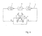
- Vibration level level switch 1 which are used as a device for detecting liquids, are vibration resonators, usually fork-type vibrator with piezoelectric drive systems, as shown in Fig. 6. These usually contain a transmitting piezoelectric element 3, which excites a designed as a fork 10 mechanical vibrating element to vibrate, and another, receiving piezoelectric element 4, which detects a vibration of the fork 10.
- a circuit which usually has an amplifier 5, a filter 6 and a comparator 7, the detected signal is amplified and the phase position of the signal is shifted so that the oscillation condition for the system is satisfied.
- the object of the invention is to provide a device or circuit in a device that also works with only one piezo element and a two-wire line, but in contrast to the previous method operates independently of both the piezoelectric capacity and the line capacity.
- a vibration level detecting device having a vibration resonator, a piezoelectric element having a piezoelectric capacitance, for exciting the vibration resonator at a driving frequency to vibrate and detecting a vibration of the vibrating resonator, two connecting conductors of the piezoelectric element, and circuit components is preferred for evaluating a vibration of the vibration resonator detected by the piezoelectric element, wherein a branch with a compensation capacitor is connected in parallel to a branch with the piezoelectric element for compensating a charge-reversal current of the piezoelectric element which is dependent on the piezoelectric capacitance.
- a piezoelectric element which has a piezoelectric capacity, excites a vibration resonator with a drive frequency to a vibration and detects a vibration of the vibration resonator, wherein connected by means of a parallel to the branch with the piezoelectric element Zweig is compensated with a compensation capacity dependent on the piezoelectric capacity Umladestroms the piezoelectric element.
- the object is thus achieved in particular by the fact that the charge-reversal current, which is dependent on the piezocapacity and the line capacitance, is compensated, in particular completely compensated.
- the compensation capacitor is designed to compensate for the charging current that is dependent on the piezocapacitance and, in addition, a line capacitance of the piezoelectric element.
- an inverter applies a signal, which is derived from the drive voltage for the piezoelectric element, to the compensation capacitor.
- a device in which a capacity of exactly or almost exactly the same size as a piezoelectric capacitance or a piezoelectric and line capacitance is switched on as a compensation capacitor.
- a device in which a tap between the piezoelectric element and the compensation capacitor is arranged for picking up a compensated signal which only contains the proportion of the mechanical vibration of the vibration resonator.
- a device is preferred in which the compensation capacitor or the electronic circuit simulating the compensation capacitor has a control input for setting the capacitance.
- a device with a compensation control is preferably used.
- the compensation control takes place by means of a compensation capacitor or by means of a compensation capacitor simulating electronic circuit to which a regulated voltage is applied.
- such a device is preferred in which a synchronous rectifier, depending on the signal or a voltage of a point directly between the piezoelectric element and the compensation capacitor controls an input signal for the compensation control provides and a frequency divider for dividing the drive frequency provides a control signal for the synchronous rectifier.
- a method is preferred in which, in addition to the piezocapacity, a line capacitance of the piezoelement is compensated.
- an inverted signal which is derived from the drive voltage for the piezoelement, is applied to a compensation capacitor with the Kompersationskapaztician.
- a method is preferred in which a compensation capacity of exactly or almost exactly the same size as the piezocapacitance or a piezoelectric and line capacitance is switched on as a compensation capacitor.
- a compensated signal is tapped between the piezoelectric element and a compensation capacitor with the compensation capacitance, which only contains the portion of the mechanical oscillation of the vibration resonator.
- a method is preferred in which a capacitance of a compensation capacitor or an electronic circuit simulating the compensation capacitor can be variably adjusted and regulated.
- a method is preferred in which a regulated voltage is applied to a compensation capacitor or its replica.
- Particularly preferred is a method in which by means of a synchronous rectifier depending on the signal or a voltage of a point directly between the piezoelectric element and the compensation capacitor an input signal for the compensation control is provided controlled and a control signal for the synchronous rectifier is provided by means of a frequency divider for dividing the drive frequency.
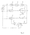
- Fig. 1 shows schematically a vibration level limit switch 1 with circuit components for its control as a device for vibration level detection of liquids.
- a vibration resonator 10 for driving a vibration resonator 10 in a vibration and for detecting a Vibration of the vibration resonator 10 is at least one piezoelectric element 11 uses, which is connected via a two-wire line 12, 13 to components of the circuit.
- the mechanical vibration of the vibrating resonator 10 can be tapped directly.
- the piezoelectric element 11 is connected via the first of its lines 12 to a buffer 14.
- the input of the buffer 14 is applied to a first node A.
- the second conductor 13 leads from the piezoelectric element 11 to a second node G.
- an inverter 15 and a capacitive device 2 are connected in series between the first node A and the second node G as a compensation capacitance.
- the compensation capacity is in principle designed here as an adjustable capacitor which has a control input for setting its effective capacity.
- the second node G is thus connected between on the one hand the piezo and, if necessary, line capacitance and on the other hand the compensation capacitance of the compensation capacitor 2.
- a measuring device 17 is connected, which is set up for the determination of the piezoelectric capacitance. From the measuring device 17, a line leads to the control input of the compensation capacitor 2 in order to control this.
- an arrangement of an amplifier 18, a filter 19 and a comparator 20 connected in series.
- the compensation of a piezoelectric and line capacitance is effected by the branch parallel to the branch with the piezoelectric element 11, in which the drive signal at the first point A is inverted to a compensation capacitance of exactly the same size as the piezoelectric and line capacitance becomes.
- a compensated signal can then be tapped off at the second point G, which signal contains only a portion of the mechanical oscillation in the form of a sinusoidal oscillation.
- the voltage resulting from the reloading of the piezoelectric element 11 is thus compensated.
- a difficulty is to measure the piezoelectric capacitance without interrupting the vibration of the vibration resonator 10.
- the compensation capacity should be stirred as exactly as possible.
- the adjustable compensation capacity 2 is to be replaced by a replica electronic circuit.
- a first adder 21 is connected whose output forms a fourth point.
- a frequency divider 22 is connected between the first point A and a further input of the first adder 21.
- the output of the frequency divider 22 forms a third point B, to which an input of a second adder 23 is also connected.
- the first node A is applied.
- the second adder 23 has a control input.
- An inverted output of the second adder 23 is applied to the input of the compensation capacitor 16.
- the output of the second adder 23 forms a fifth point F.
- a switching device 25 Connected to the second point G via a resistive and another capacitive device 24 is a switching device 25 which, as a synchronous rectifier, applies the signal of the second point G to either a ground connection or a negative input of a compensation voltage regulation 27.
- the negative input of the compensation voltage control 27 via a further capacitive device 26th connected to the ground terminal or a base voltage.
- the positive input of the compensation voltage regulator 27 is also applied to the ground terminal.
- An output of the compensation voltage control 27 is applied to the second adder 23 as a control signal.
- At a switching input of the switching device 25 is a signal of the third point B at.
- a second voltage is generated from the drive voltage of the first point A as a capacitance measurement voltage at the third point B.
- a divider ratio of one quarter of the frequency f / 4 is selected.
- the capacitance measuring voltage at the third point B is superimposed by adding the drive voltage at the first point A, so that a superimposed voltage at the fourth point E is formed.
- an inverted voltage is generated at the fifth point F in a second pointer.
- This voltage is adjustable in amplitude, whereby an adjustable compensation capacity can be simulated.
- the compensation capacitor 16 itself remains constant, wherein the quantity of charge which the compensation capacitor 16 can store is changed via the magnitude of the voltage.
- the piezoelectric element 11 and the series-connected compensation capacitor are driven.
- the charge-reversal voltages at the second point G compensate each other between the two capacities.
- the frequency of the capacitance measuring voltage at the third point B is outside the mechanical resonance of the vibration resonator 10.
- the piezoelectric capacitance is compared with the compensation capacity.
- the voltage for this frequency at the second point G between capacitances is zero. In the case of a fault compensation, an error voltage arises at this second point G.
- This error voltage can be evaluated by means of the synchronous rectifier, which is formed by the switching device 25 as a measuring device. Since the mechanical resonance vibration of the vibration resonator 10 is a multiple of the capacitance measuring voltage B with which the synchronous rectifier is driven, a voltage is obtained after the rectification, which depends only on the piezo and compensation capacitance.
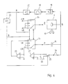
- FIG. 3 A practical embodiment with waveforms at various points of the circuit when carrying out the preferred method is shown in FIG. 3.
- the first point A with the drive voltage and the output of the frequency divider 22, i. the third point B, are connected to inputs of an EXOR gate 28 (E-XOR: exclusive-or). Its output forms a sixth point D, which applies a switching signal to a second and third switching devices 29, 30.
- E-XOR exclusive-or
- the signal at the third point B is applied to the synchronous rectifier 25 as a switching signal.
- This and other components are connected as in Fig. 2 between the second point G and the compensation voltage control 27.
- the output of the compensation voltage control 27 is applied as a positive compensation voltage + UK to a switching input of a fourth switching device 31.
- the output of the compensation voltage regulator 27 is also applied to a negative input of a compensation voltage inversion 33, whose second negative input is connected to the ground connection.
- the output of the compensation voltage inversion 33 is applied to the fourth switching device 31 as the negative compensation voltage -UK.
- the switched output of the fourth switching device 31 is applied to the first switching input of the third switching device 30.
- the output of the third switching device 30 is applied to the fifth node F, which forms the input for the compensation capacitor 16. This is in turn connected via the second point G to the piezoelectric element 11.
- the input of the piezoelectric element 11 forms the fourth point E, which is applied to the output of the second switching device 29.
- a first input of the second switching device 29 is correspondingly switched equal to the switching input of the third switching device 30, which rests against the fourth switching device 31.
- the other two switching inputs of the second and third switching means 29, 30 are applied to the ground terminal.
- the first switching input of the second switching device 29 forms a seventh point and is applied to an output of a fifth switching device 32.
- Their switching inputs are connected to a positive or negative operating voltage + UB, -UB.
- the signal of the third point B is applied.
- the voltages at the fourth point E and the fifth point F are respectively generated via the second to fifth switching devices 29-32 as switches and the EXOR gate 28.
- 4 shows a further expedient embodiment of the circuit arrangement, wherein only the components and functions that are different from the embodiment according to FIG. 3 are described below.
- a first and a second multiplexer 34, 35 used in the circuit.
- the signal forms at the fourth point E and at the fifth point F are thus generated via analog multiplex components.
- the first point A with the drive voltage is connected to a switching input of the first multiplexer 34 and to a switching input of the second multiplexer 35.
- the third point B is connected to the signal of the frequency divider 22 to a further switching input of the first multiplexer 34 and to a further switching input of the second multiplexer 35.
- the output of the compensation voltage regulator 27 is applied as a positive compensation voltage + UK to a signal input of the first multiplexer 34.
- the output of the compensation voltage regulator 27 is also applied to a negative input of the compensation voltage inverter 33 whose second negative input is applied to the ground terminal.
- the output of the compensation voltage conversion 33 is applied as a negative compensation voltage -UK to a further signal input of the first multiplexer 34.
- Two further signal inputs of the first multiplexer 34 are connected to the ground terminal.
- the switched output of the first multiplexer 34 is connected to the fifth point F, which forms the input for the compensation capacitor 16. This is in turn connected via the second point G to the piezoelectric element 11.
- the input of the piezoelectric element 11 again forms the fourth point E, which abuts the output of the second multiplexer 35 in this embodiment.
- a first and a fourth signal input of the second multiplexer 35 are applied to a positive or, at a negative operating voltage + UB, -UB.
- a second and a third signal input of the second multiplexer 35 are connected to the ground terminal.
- the ability to measure the piezo capacitance very accurately results in further advantages.
- a line break and a short circuit of the cables to the vibration sensor can be reliably detected.
- a change in the piezoelectric capacitance may indicate damage to the piezoelectric element 11.
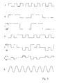
- Fig. 5 shows voltage and signal waveforms at the different points to each other in an exemplary time sequence.
- first point A is applied as a drive voltage to a simple clocked signal whose frequency corresponds in normal operation to the mechanical resonance vibration of the vibration resonator.
- third point B is a clock having a period of the duration of four periods of the drive signal at the point A.
- seventh point C is a clocked voltage equal to the operating voltage + UB, -UB, the clock corresponds to that of the signal at the third point B.
- the sixth point D is a clocked switched signal, which is obtained by an EXOR operation of the signals A and B of FIG.
- Waveforms at the fourth and fifth points E, F are inversely to each other and depend on the level of the operating voltage + UB, -UB and the compensation voltage -UK, + UK. These signals change the clocked state parallel to the state of the signal at the sixth point D and in addition to the end of a period of the signal at the third point B.
- At the second point G is a sinusoidal output signal of the piezoelectric element 11, which forms a compensated measurement signal of the piezoelectric element 11 and the resonance vibration of the vibration resonator corresponds.
- the capacitance measuring voltage it is also possible not to generate the capacitance measuring voltage by frequency division from the drive voltage, but to feed a fixed frequency, which comes for example from a microprocessor.
- the oscillation on the mechanical resonance should be interrupted for the time of the capacitance measurement, since otherwise beats with very low frequencies may occur. An interruption of the mechanical vibration would increase the reaction time of the device.
Landscapes
- Physics & Mathematics (AREA)
- Acoustics & Sound (AREA)
- Electromagnetism (AREA)
- Thermal Sciences (AREA)
- Fluid Mechanics (AREA)
- General Physics & Mathematics (AREA)
- Oscillators With Electromechanical Resonators (AREA)
- Dc-Dc Converters (AREA)
- General Electrical Machinery Utilizing Piezoelectricity, Electrostriction Or Magnetostriction (AREA)
- Gyroscopes (AREA)
- Measurement Of Levels Of Liquids Or Fluent Solid Materials (AREA)
Applications Claiming Priority (1)
| Application Number | Priority Date | Filing Date | Title |
|---|---|---|---|
| DE102005036872.7A DE102005036872B4 (de) | 2005-08-02 | 2005-08-02 | Vorrichtung zur Vibrations-Füllstand-Grenzstanderfassung und Verfahren zur Vibrations-Füllstand-Grenzstanderfassung |
Publications (3)
| Publication Number | Publication Date |
|---|---|
| EP1750104A2 true EP1750104A2 (fr) | 2007-02-07 |
| EP1750104A3 EP1750104A3 (fr) | 2008-08-06 |
| EP1750104B1 EP1750104B1 (fr) | 2011-12-28 |
Family
ID=37420829
Family Applications (1)
| Application Number | Title | Priority Date | Filing Date |
|---|---|---|---|
| EP06010806A Ceased EP1750104B1 (fr) | 2005-08-02 | 2006-05-26 | Dispositif et procédé destinés à l'enregistrement d'un niveau seuil de remplissage à vibrations |
Country Status (4)
| Country | Link |
|---|---|
| US (1) | US7723898B2 (fr) |
| EP (1) | EP1750104B1 (fr) |
| CN (1) | CN100472186C (fr) |
| DE (1) | DE102005036872B4 (fr) |
Cited By (3)
| Publication number | Priority date | Publication date | Assignee | Title |
|---|---|---|---|---|
| WO2010006896A1 (fr) * | 2008-07-14 | 2010-01-21 | Endress+Hauser Gmbh+Co.Kg | Dispositif pour déterminer et/ou transmettre une grandeur de processus et procédé pour contrôler un dispositif |
| WO2012000814A1 (fr) | 2010-07-01 | 2012-01-05 | Endress+Hauser Gmbh+Co.Kg | Dispositif pour déterminer et/ou surveiller une grandeur de processus d'un milieu |
| WO2012022542A1 (fr) * | 2010-08-20 | 2012-02-23 | Endress+Hauser Gmbh+Co.Kg | Dispositif de détermination et/ou de contrôle d'au moins un niveau de remplissage prédéfini |
Families Citing this family (7)
| Publication number | Priority date | Publication date | Assignee | Title |
|---|---|---|---|---|
| KR100934222B1 (ko) * | 2007-08-29 | 2009-12-29 | 한국전자통신연구원 | 고해상도의 정전용량-시간 변환 회로 |
| DE102008050266A1 (de) * | 2008-10-07 | 2010-04-08 | Endress + Hauser Gmbh + Co. Kg | Vorrichtung zur Bestimmung und/oder Überwachung einer Prozessgröße eines Mediums |
| DE102013114045A1 (de) * | 2013-12-13 | 2015-06-18 | Endress + Hauser Gmbh + Co. Kg | System zur Bestimmung und/oder Überwachung einer Prozessgröße eines Mediums |
| DE102014107927A1 (de) * | 2014-06-05 | 2015-12-17 | Endress + Hauser Gmbh + Co. Kg | Verfahren und Vorrichtung zur Überwachung des Füllstandes eines Mediums in einem Behälter |
| US10451467B2 (en) * | 2014-10-08 | 2019-10-22 | Semiconductor Components Industries, Llc | Level sensor and method |
| DE102015121621B4 (de) * | 2015-12-11 | 2018-03-01 | Endress+Hauser Gmbh+Co. Kg | Vorrichtung zur sicheren Bestimmung und/oder Überwachung einer Prozessgröße |
| US11217392B2 (en) | 2019-01-17 | 2022-01-04 | Samsung Electronics Co., Ltd. | Composite piezoelectric capacitor |
Citations (1)
| Publication number | Priority date | Publication date | Assignee | Title |
|---|---|---|---|---|
| DE19621449C2 (de) | 1996-05-29 | 2000-11-30 | Grieshaber Vega Kg | Vibrationsresonator, Verfahren zum Betreiben eines solchen Vibrationsresonators und Vibrations-Füllstand-Grenzschalter mit einem solchen Vibrationsresonator |
Family Cites Families (15)
| Publication number | Priority date | Publication date | Assignee | Title |
|---|---|---|---|---|
| GB1095436A (fr) * | ||||
| CN87101629A (zh) * | 1987-03-04 | 1987-10-07 | 中国矿业学院 | 料位智能测量及控制系统 |
| CN2121020U (zh) * | 1992-04-17 | 1992-11-04 | 卢亮 | 数字电容式料位计 |
| JPH08233581A (ja) * | 1994-12-28 | 1996-09-13 | Yoshiro Tomikawa | 静電型変換手段の駆動装置 |
| DE10023306C2 (de) * | 2000-05-15 | 2002-07-11 | Grieshaber Vega Kg | Verfahren zur Ansteuerung von piezoelektrischen Antrieben in Füllstandmessgeräten |
| DE10056353A1 (de) * | 2000-11-14 | 2002-05-23 | Grieshaber Vega Kg | Verfahren und Anordnung zur Füllstandsmessung |
| JP3998233B2 (ja) * | 2001-11-09 | 2007-10-24 | セイコーNpc株式会社 | 発振回路および発振用集積回路 |
| US6919689B2 (en) * | 2002-09-26 | 2005-07-19 | Lam Research Corporation | Method for toolmatching and troubleshooting a plasma processing system |
| DE10328113B4 (de) * | 2002-12-13 | 2006-07-20 | Endress + Hauser Gmbh + Co. Kg | Vorrichtung zum Betreiben einer schwingfähigen Einheit eines Vibrationsresonators |
| DE10331428B4 (de) * | 2003-07-10 | 2005-07-28 | Endress + Hauser Gmbh + Co. Kg | Feldgerät zur Bestimmung und/oder Überwachung einer Prozessgröße |
| US6867729B2 (en) * | 2003-07-30 | 2005-03-15 | Magnetrol International | Guided wave radar level transmitter with automatic velocity compensation |
| JP2005137071A (ja) * | 2003-10-29 | 2005-05-26 | Hitachi Ltd | 振動発電装置 |
| US7323805B2 (en) * | 2004-01-28 | 2008-01-29 | Kabushiki Kaisha Toshiba | Piezoelectric thin film device and method for manufacturing the same |
| US7146845B2 (en) * | 2004-03-24 | 2006-12-12 | Vega Grieshaber Kg | Method for operating tests of vibration level switch sensors and corresponding vibration level switch |
| CN1282866C (zh) * | 2004-12-23 | 2006-11-01 | 太原理工大学 | 数字化雷达物位计 |
-
2005
- 2005-08-02 DE DE102005036872.7A patent/DE102005036872B4/de not_active Expired - Fee Related
-
2006
- 2006-05-26 EP EP06010806A patent/EP1750104B1/fr not_active Ceased
- 2006-07-11 CN CNB2006101019231A patent/CN100472186C/zh not_active Expired - Fee Related
- 2006-08-01 US US11/496,584 patent/US7723898B2/en active Active
Patent Citations (1)
| Publication number | Priority date | Publication date | Assignee | Title |
|---|---|---|---|---|
| DE19621449C2 (de) | 1996-05-29 | 2000-11-30 | Grieshaber Vega Kg | Vibrationsresonator, Verfahren zum Betreiben eines solchen Vibrationsresonators und Vibrations-Füllstand-Grenzschalter mit einem solchen Vibrationsresonator |
Cited By (6)
| Publication number | Priority date | Publication date | Assignee | Title |
|---|---|---|---|---|
| WO2010006896A1 (fr) * | 2008-07-14 | 2010-01-21 | Endress+Hauser Gmbh+Co.Kg | Dispositif pour déterminer et/ou transmettre une grandeur de processus et procédé pour contrôler un dispositif |
| WO2012000814A1 (fr) | 2010-07-01 | 2012-01-05 | Endress+Hauser Gmbh+Co.Kg | Dispositif pour déterminer et/ou surveiller une grandeur de processus d'un milieu |
| DE102010030791A1 (de) | 2010-07-01 | 2012-01-05 | Endress + Hauser Gmbh + Co. Kg | Vorrichtung zur Bestimmung und/oder Überwachung einer Prozessgröße eines Mediums |
| US9448097B2 (en) | 2010-07-01 | 2016-09-20 | Endress + Hauser Gmbh + Co. Kg | Apparatus for determining and/or monitoring a process variable of a medium |
| WO2012022542A1 (fr) * | 2010-08-20 | 2012-02-23 | Endress+Hauser Gmbh+Co.Kg | Dispositif de détermination et/ou de contrôle d'au moins un niveau de remplissage prédéfini |
| US9989398B2 (en) | 2010-08-20 | 2018-06-05 | Endress + Hauser Gmbh + Co. Kg | Device for determining and/or monitoring at least one predetermined fill level |
Also Published As
| Publication number | Publication date |
|---|---|
| DE102005036872A1 (de) | 2007-02-08 |
| EP1750104A3 (fr) | 2008-08-06 |
| DE102005036872B4 (de) | 2016-03-24 |
| CN100472186C (zh) | 2009-03-25 |
| US20070029897A1 (en) | 2007-02-08 |
| EP1750104B1 (fr) | 2011-12-28 |
| US7723898B2 (en) | 2010-05-25 |
| CN1908597A (zh) | 2007-02-07 |
Similar Documents
| Publication | Publication Date | Title |
|---|---|---|
| EP2588842B1 (fr) | Dispositif pour déterminer et/ou surveiller une grandeur de processus d'un milieu | |
| DE102013218973B4 (de) | Verfahren und Schaltung zur zeitkontinuierlichen Detektion der Position der Sensormasse bei gleichzeitiger Rückkopplung für kapazitive Sensoren | |
| EP2798319B1 (fr) | Dispositif de détermination et/ou de surveillance d'au moins une grandeur de processus | |
| EP3329246B1 (fr) | Déphaseur pour capteur vibronique | |
| EP0503272B1 (fr) | Agencement de circuits pour mesurer le quotient de capacitances de deux condensateurs | |
| WO2003071233A1 (fr) | Dispositif et procede de lecture d'un condensateur differentiel comportant un premier et un deuxieme condensateur partiel | |
| EP0813306A1 (fr) | Oscillateur stabilisé en température et commutateur de proximité en faisant usage | |
| EP1750104B1 (fr) | Dispositif et procédé destinés à l'enregistrement d'un niveau seuil de remplissage à vibrations | |
| DE4135624A1 (de) | Verfahren zur lagesteuerung eines sensorbauteils, sowie kraftbalanciertes sensorinstrument mit elektrostatischer ladungssteuerung | |
| CH657457A5 (de) | Pruefeinrichtung zur bestimmung von schwingungseigenschaften mindestens eines messwertaufnehmers. | |
| EP1470408B1 (fr) | Dispositif de mesure de viscosite et/ou de densite | |
| EP3513152B1 (fr) | Compensation d'un changement de phase d'au moins un composant électronique d'un capteur vibronique | |
| CH634922A5 (de) | Einrichtung zum messen der akustischen eigenschaften und deren aenderungen einer probe. | |
| DE3642771C2 (fr) | ||
| EP1836458B1 (fr) | Circuit oscillant | |
| EP2233890A2 (fr) | Capteur capacitif et procédé de détection capacitive de l'écartement d'un objet | |
| EP3117182B1 (fr) | Procédé pour optimer le temps de démarrage d'un gyroscope coriolis et gyroscope coriolis à cet effet | |
| EP2390634B1 (fr) | Dispositif de fonctionnement d'une unité pivotante d'un résonateur à vibrations | |
| EP0343403B1 (fr) | Circuit pour l'auto-excitation d'un oscillateur mécanique jusqu'à sa fréquence de résonance propre | |
| EP4122100B1 (fr) | Capteur de proximité capacitif | |
| EP2876412B1 (fr) | Capteur inertiel ainsi que dispositif et procédé de fonctionnement d'un capteur inertiel | |
| DE102019202326B3 (de) | Verfahren zum Betreiben eines kapazitiven MEMS-Sensors sowie kapazitiver MEMS-Sensor | |
| DE102019102204B4 (de) | Verfahren und Schaltungsanordnung zum Betreiben eines Vibrationssensors mit integrierter Temperaturerfassung | |
| EP1693663A2 (fr) | Procédé et dispositif de determination de deux paramètres d'un fluide | |
| EP4602376A1 (fr) | Procédé et dispositif de mesure de tension |
Legal Events
| Date | Code | Title | Description |
|---|---|---|---|
| PUAI | Public reference made under article 153(3) epc to a published international application that has entered the european phase |
Free format text: ORIGINAL CODE: 0009012 |
|
| AK | Designated contracting states |
Kind code of ref document: A2 Designated state(s): AT BE BG CH CY CZ DE DK EE ES FI FR GB GR HU IE IS IT LI LT LU LV MC NL PL PT RO SE SI SK TR |
|
| AX | Request for extension of the european patent |
Extension state: AL BA HR MK YU |
|
| PUAL | Search report despatched |
Free format text: ORIGINAL CODE: 0009013 |
|
| AK | Designated contracting states |
Kind code of ref document: A3 Designated state(s): AT BE BG CH CY CZ DE DK EE ES FI FR GB GR HU IE IS IT LI LT LU LV MC NL PL PT RO SE SI SK TR |
|
| AX | Request for extension of the european patent |
Extension state: AL BA HR MK YU |
|
| RIC1 | Information provided on ipc code assigned before grant |
Ipc: G01F 23/296 20060101AFI20061123BHEP Ipc: B06B 1/02 20060101ALI20080630BHEP |
|
| 17P | Request for examination filed |
Effective date: 20080917 |
|
| 17Q | First examination report despatched |
Effective date: 20081015 |
|
| AKX | Designation fees paid |
Designated state(s): DE FR GB HU |
|
| GRAP | Despatch of communication of intention to grant a patent |
Free format text: ORIGINAL CODE: EPIDOSNIGR1 |
|
| GRAS | Grant fee paid |
Free format text: ORIGINAL CODE: EPIDOSNIGR3 |
|
| GRAA | (expected) grant |
Free format text: ORIGINAL CODE: 0009210 |
|
| AK | Designated contracting states |
Kind code of ref document: B1 Designated state(s): DE FR GB HU |
|
| REG | Reference to a national code |
Ref country code: GB Ref legal event code: FG4D Free format text: NOT ENGLISH |
|
| REG | Reference to a national code |
Ref country code: DE Ref legal event code: R096 Ref document number: 502006010761 Country of ref document: DE Effective date: 20120308 |
|
| PLBE | No opposition filed within time limit |
Free format text: ORIGINAL CODE: 0009261 |
|
| STAA | Information on the status of an ep patent application or granted ep patent |
Free format text: STATUS: NO OPPOSITION FILED WITHIN TIME LIMIT |
|
| 26N | No opposition filed |
Effective date: 20121001 |
|
| REG | Reference to a national code |
Ref country code: DE Ref legal event code: R097 Ref document number: 502006010761 Country of ref document: DE Effective date: 20121001 |
|
| REG | Reference to a national code |
Ref country code: HU Ref legal event code: AG4A Ref document number: E015209 Country of ref document: HU |
|
| REG | Reference to a national code |
Ref country code: FR Ref legal event code: PLFP Year of fee payment: 11 |
|
| REG | Reference to a national code |
Ref country code: FR Ref legal event code: PLFP Year of fee payment: 12 |
|
| REG | Reference to a national code |
Ref country code: FR Ref legal event code: PLFP Year of fee payment: 13 |
|
| PGFP | Annual fee paid to national office [announced via postgrant information from national office to epo] |
Ref country code: DE Payment date: 20210525 Year of fee payment: 16 Ref country code: FR Payment date: 20210525 Year of fee payment: 16 |
|
| PGFP | Annual fee paid to national office [announced via postgrant information from national office to epo] |
Ref country code: HU Payment date: 20210523 Year of fee payment: 16 Ref country code: GB Payment date: 20210526 Year of fee payment: 16 |
|
| REG | Reference to a national code |
Ref country code: DE Ref legal event code: R119 Ref document number: 502006010761 Country of ref document: DE |
|
| GBPC | Gb: european patent ceased through non-payment of renewal fee |
Effective date: 20220526 |
|
| PG25 | Lapsed in a contracting state [announced via postgrant information from national office to epo] |
Ref country code: HU Free format text: LAPSE BECAUSE OF NON-PAYMENT OF DUE FEES Effective date: 20220527 |
|
| PG25 | Lapsed in a contracting state [announced via postgrant information from national office to epo] |
Ref country code: FR Free format text: LAPSE BECAUSE OF NON-PAYMENT OF DUE FEES Effective date: 20220531 |
|
| PG25 | Lapsed in a contracting state [announced via postgrant information from national office to epo] |
Ref country code: GB Free format text: LAPSE BECAUSE OF NON-PAYMENT OF DUE FEES Effective date: 20220526 Ref country code: DE Free format text: LAPSE BECAUSE OF NON-PAYMENT OF DUE FEES Effective date: 20221201 |
|
| P01 | Opt-out of the competence of the unified patent court (upc) registered |
Effective date: 20230626 |