EP1750180B1 - Dispositif de formation d'images en couleur - Google Patents
Dispositif de formation d'images en couleur Download PDFInfo
- Publication number
- EP1750180B1 EP1750180B1 EP06254042A EP06254042A EP1750180B1 EP 1750180 B1 EP1750180 B1 EP 1750180B1 EP 06254042 A EP06254042 A EP 06254042A EP 06254042 A EP06254042 A EP 06254042A EP 1750180 B1 EP1750180 B1 EP 1750180B1
- Authority
- EP
- European Patent Office
- Prior art keywords
- image
- correction
- color
- colour
- image forming
- Prior art date
- Legal status (The legal status is an assumption and is not a legal conclusion. Google has not performed a legal analysis and makes no representation as to the accuracy of the status listed.)
- Ceased
Links
- 230000015572 biosynthetic process Effects 0.000 claims description 150
- 238000012937 correction Methods 0.000 claims description 52
- 239000003086 colorant Substances 0.000 claims description 47
- 238000000034 method Methods 0.000 claims description 25
- 238000012546 transfer Methods 0.000 claims description 20
- 238000012545 processing Methods 0.000 claims description 17
- 238000007639 printing Methods 0.000 claims description 15
- 238000011144 upstream manufacturing Methods 0.000 claims description 15
- 238000005259 measurement Methods 0.000 claims description 11
- 230000008569 process Effects 0.000 claims description 9
- 239000002131 composite material Substances 0.000 claims description 4
- 230000007246 mechanism Effects 0.000 claims 1
- 230000032258 transport Effects 0.000 description 84
- 238000001514 detection method Methods 0.000 description 56
- 230000003287 optical effect Effects 0.000 description 21
- 230000008859 change Effects 0.000 description 16
- 239000000203 mixture Substances 0.000 description 10
- 238000004886 process control Methods 0.000 description 9
- 230000003111 delayed effect Effects 0.000 description 8
- 238000011161 development Methods 0.000 description 7
- 230000018109 developmental process Effects 0.000 description 7
- 238000010586 diagram Methods 0.000 description 7
- 238000000691 measurement method Methods 0.000 description 6
- 238000004904 shortening Methods 0.000 description 6
- 238000005070 sampling Methods 0.000 description 5
- 230000006870 function Effects 0.000 description 4
- 230000009471 action Effects 0.000 description 3
- 230000015556 catabolic process Effects 0.000 description 1
- 238000006731 degradation reaction Methods 0.000 description 1
- 238000005516 engineering process Methods 0.000 description 1
- 230000006872 improvement Effects 0.000 description 1
- 230000009467 reduction Effects 0.000 description 1
- 230000007261 regionalization Effects 0.000 description 1
Images




Classifications
-
- G—PHYSICS
- G03—PHOTOGRAPHY; CINEMATOGRAPHY; ANALOGOUS TECHNIQUES USING WAVES OTHER THAN OPTICAL WAVES; ELECTROGRAPHY; HOLOGRAPHY
- G03G—ELECTROGRAPHY; ELECTROPHOTOGRAPHY; MAGNETOGRAPHY
- G03G15/00—Apparatus for electrographic processes using a charge pattern
- G03G15/50—Machine control of apparatus for electrographic processes using a charge pattern, e.g. regulating differents parts of the machine, multimode copiers, microprocessor control
- G03G15/5054—Machine control of apparatus for electrographic processes using a charge pattern, e.g. regulating differents parts of the machine, multimode copiers, microprocessor control by measuring the characteristics of an intermediate image carrying member or the characteristics of an image on an intermediate image carrying member, e.g. intermediate transfer belt or drum, conveyor belt
- G03G15/5058—Machine control of apparatus for electrographic processes using a charge pattern, e.g. regulating differents parts of the machine, multimode copiers, microprocessor control by measuring the characteristics of an intermediate image carrying member or the characteristics of an image on an intermediate image carrying member, e.g. intermediate transfer belt or drum, conveyor belt using a test patch
-
- G—PHYSICS
- G03—PHOTOGRAPHY; CINEMATOGRAPHY; ANALOGOUS TECHNIQUES USING WAVES OTHER THAN OPTICAL WAVES; ELECTROGRAPHY; HOLOGRAPHY
- G03G—ELECTROGRAPHY; ELECTROPHOTOGRAPHY; MAGNETOGRAPHY
- G03G15/00—Apparatus for electrographic processes using a charge pattern
- G03G15/01—Apparatus for electrographic processes using a charge pattern for producing multicoloured copies
- G03G15/0142—Structure of complete machines
- G03G15/0178—Structure of complete machines using more than one reusable electrographic recording member, e.g. one for every monocolour image
- G03G15/0194—Structure of complete machines using more than one reusable electrographic recording member, e.g. one for every monocolour image primary transfer to the final recording medium
-
- G—PHYSICS
- G03—PHOTOGRAPHY; CINEMATOGRAPHY; ANALOGOUS TECHNIQUES USING WAVES OTHER THAN OPTICAL WAVES; ELECTROGRAPHY; HOLOGRAPHY
- G03G—ELECTROGRAPHY; ELECTROPHOTOGRAPHY; MAGNETOGRAPHY
- G03G2215/00—Apparatus for electrophotographic processes
- G03G2215/00025—Machine control, e.g. regulating different parts of the machine
- G03G2215/00029—Image density detection
- G03G2215/00059—Image density detection on intermediate image carrying member, e.g. transfer belt
-
- G—PHYSICS
- G03—PHOTOGRAPHY; CINEMATOGRAPHY; ANALOGOUS TECHNIQUES USING WAVES OTHER THAN OPTICAL WAVES; ELECTROGRAPHY; HOLOGRAPHY
- G03G—ELECTROGRAPHY; ELECTROPHOTOGRAPHY; MAGNETOGRAPHY
- G03G2215/00—Apparatus for electrophotographic processes
- G03G2215/01—Apparatus for electrophotographic processes for producing multicoloured copies
- G03G2215/0103—Plural electrographic recording members
- G03G2215/0119—Linear arrangement adjacent plural transfer points
-
- G—PHYSICS
- G03—PHOTOGRAPHY; CINEMATOGRAPHY; ANALOGOUS TECHNIQUES USING WAVES OTHER THAN OPTICAL WAVES; ELECTROGRAPHY; HOLOGRAPHY
- G03G—ELECTROGRAPHY; ELECTROPHOTOGRAPHY; MAGNETOGRAPHY
- G03G2215/00—Apparatus for electrophotographic processes
- G03G2215/01—Apparatus for electrophotographic processes for producing multicoloured copies
- G03G2215/0151—Apparatus for electrophotographic processes for producing multicoloured copies characterised by the technical problem
- G03G2215/0158—Colour registration
- G03G2215/0161—Generation of registration marks
Definitions
- the present invention relates to a tandem-type color image forming device, such as a laser printer, a digital copier or a facsimile device, in which color component images are written to respective photoconductors through light beam scanning and a color image is formed on an image support medium through superimposing of the color component images. More particularly, the present invention relates to a color image forming device which is provided with a correction-pattern image forming unit adapted for correction of the image formation operating states for each color component.
- the light scanning method which performs the optical image writing to the photoconductor by the scanning of a light beam (e.g., laser beam) is commonly used.
- the photoconductor is periodically scanned in the main scanning direction by the scanning unit, such as a polygon mirror, through the scanning of a laser beam the light emission control of which is performed in accordance with a video signal (line image signal).
- the scanned surface of the photoconductor is moved in the sub-scanning direction (which is perpendicular to the main scanning direction). A two-dimensional image is formed on the photoconductor by performing the exposure scanning.
- the electrostatic latent image formed on the photoconductor by the exposure scanning is subjected to each of respective processes of the development using toner, the image transfer to a recording medium or copy sheet (which may include an intermediate transfer medium), and the fixing of the image to the recording medium. After these processes, the image formation processing is completed.
- a color image is formed using the light beam scanning method
- the scanning of a light beam to the photoconductor is performed for each of respective color components, and a color composite image is produced through the superimposing the color-component images.
- this processing there are known the two major methods.
- One is the single-photoconductor method in which the color superimposing is performed in the optical writing or image transfer process using the single photoconductor that is common to each color component.
- the other is the tandem type method in which the color superimposing is performed in the image transfer process using a plurality of photoconductors corresponding to the respective color components.
- the exposure scanning is performed to the photoconductor of each color component respectively, and then the color superimposing is performed. And it is necessary to manage the image formation process so as to prevent occurrence of deviations between the respective color component images. For this reason, it is necessary to output an appropriate color image by measuring or detecting the image formation state of each of the color component images and adjusting the operating conditions in accordance with a detected change of the image formation state.
- Japanese Published Application No. 07-019085 Japanese Patent No. 3644923 , and Japanese Laid-Open Patent Application No. 2004-101567 disclose examples of the operating-state measurement method according to the related art which is used for the tandem type method.
- the measurement method of Japanese Published Application No. 07-019085 is to measure a color deviation in the copy sheet transport direction by forming a pattern image of each color on the transport (transfer) belt, on the conditions that it is formed in the transport direction at predetermined intervals during operation without any error, and by detecting a change in the pattern image. That is, the pattern image of each color actually formed at the time of measurement reflects variations in the image formation operating states for each color and includes a positional deviation of the interval between the pattern images. This deviation is detected by a sensor, and the image write timing is adjusted in accordance with the detected signal from the sensor.
- the measurement method of Japanese Patent No. 3644923 is based on the above-mentioned method of Japanese Published Application No. 07-019085 wherein the pattern image of each color is formed on the transport (transfer) belt.
- this method in addition to the positional deviation between the pattern images of the respective colors, other deviations, due to errors of a sub-scanning registration (or the above-mentioned deviation in the copy sheet transport direction), an inclination (skew), a main-scanning registration and a scanning magnification, are also included. For this reason, a sequence of positioning toner marks for detecting a deviation is formed at three detection positions on the transport belt arrayed in the main scanning direction.
- the optical density detection toner mark (patch) for optical density detection of each color is also formed, and the detection unit for detecting the positional deviation is shared for detection of this optical density detection toner mark.
- the processing of the detection data which optimizes positioning is performed on the basis of detection of the positioning toner marks for detection of positional deviation between the images of each color as in the method of Japanese Patent No. 3644923 .
- the above adjustment is carried out for the exposure scanning unit by adjusting the timing of image writing, the drive of the photoconductor or the amount of light exposure. Or the above adjustment is carried out for the toner development unit by adjusting the development bias or the charging bias. Since the state of the system changes temporally, the above adjustment must be performed at appropriate timing.
- the toner marks on the transport (transfer) belt are formed in accordance with the predetermined conditions for this purpose.
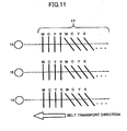
- FIG. 11 shows the arrangement of toner marks for detection of positional deviation between the respective colors according to the art related to the invention.
- a mark sequence 17' which includes four lateral lines and four slanting lines of the respective colors arranged at predetermined intervals is set up as one group, and this mark sequence 17' is formed at each of detection positions of the sensors 14, 15 and 16 which are disposed on the transport belt at three different locations in the main scanning direction.
- the mark sequence 17' shown in FIG. 11 is similar to the deviation detection toner marks as disclosed in Japanese Patent No. 3644923 or Japanese Laid-Open Patent Application No. 2004-101567 .
- the letters M, C, Y and K indicated in the mark sequence in FIG. 11 denote the respective color components (M: magenta, C: cyan, Y: yellow, K: black).
- the mark sequence 17' (or deviation detection marks) is formed on the transport belt during a special operation mode (which is called correction mode) which is performed to correct the image formation operating states, and this correction mode is different from the normal printing mode (which is also called normal printing) which is performed to form an image on a copy sheet.
- correction mode a special operation mode which is performed to correct the image formation operating states
- normal printing mode which is also called normal printing
- the toner marks are formed on the transport belt in the sequence: M-C-Y-K, as shown in FIG. 11 , along the belt transport direction.
- the photoconductor drums of the respective color components are arranged in the sequence of M-C-Y-K in the direction from the upstream to the downstream of the transport belt, and the marks of the respective colors are assigned to the image formation areas of the respective colors arranged in a sequence that is the same as the sequence of the photoconductor drums in the above-mentioned arrangement.
- FIG. 12 shows the arrangement of the image formation areas on the transport belt to which the toner marks of the respective colors are assigned according to art related to the invention.
- the uppermost position in the mark sequence upstream of the belt transport direction is set to M.
- the area "a" (where “a” denotes the length of the mark in the belt transport direction) is assigned for each of the respective colors along the sequence of M-C-Y-K, respectively, and the mark of each color is formed therein.
- the mark sequence in the belt transport direction is constituted in this manner.
- the area "a" is assigned for each of the respective colors.
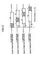
- FIG. 13 is a timing chart for explaining the image formation area signals which cause the toner marks of the respective colors to be formed in the assigned image formation areas.
- the Low period is the write-enable period in which image formation is possible
- the shaded rectangular signal portion is the period (assigned for image formation) in which the toner mark of the color concerned is formed on the transport belt.
- the pitch between two adjacent ones of the photoconductors of the respective colors is set to "b" (mm), and the timing of each image formation area signal is adjusted so that the toner marks of the respective colors are respectively formed in the assigned image formation areas on the transport belt.
- the photoconductor of M arranged in the uppermost position upstream of the belt transport direction is set in the write-enable period in which image formation is possible, and the mark of M is formed in the head-end image formation area on the transport belt.
- the period of the photoconductor pitch "b" is delayed from the start, the photoconductor of C arranged in the second uppermost position upstream of the belt transport direction is set in the write-enable period in which image formation is possible, and the mark of C is formed in the second image formation area on the transport belt.
- the mark of Y is formed in the third image formation area on the transport belt.
- the period "3b" is delayed from the start, and the final mark of K is formed in the last image formation area on the transport belt.
- the total period "4a+3b" is needed from the start of formation of the first mark of M to the end of formation of the last mark of K.
- the correction mode is automatically performed if a print request is received from the operation panel by the user and a change of the image formation operating state of the image forming device which degrades the image quality, such as a color deviation, takes place.
- a change may take place when printing documents more than a predetermined number of sheets is performed, or the image forming device starts operation from the idle state, such as power supply ON, or a temperature change arises which causes the operating state of the device, such as the exposure scanning unit, to change.
- JP-A-2004-117896 discloses a color image forming apparatus in which color registration correction patterns are formed all at the same time and is the same order as defined by the positional arrangement of the four image color units in order to decrease the time needed from start to and of correction procedure.
- an improved color image forming device in which the above-described problems are eliminated.
- tandem type color image forming device which minimizes the time needed for forming the toner marks in the toner mark formation processing in the correction mode, thereby making the fall of productivity as small as possible.
- the invention is applied to a tandem type color image forming device using the electrophotographic process which performs LD (laser diode) light writing of a two-dimensional image on a photoconductor in the main scanning direction and the sub-scanning direction.
- LD laser diode
- the photoconductors of respective colors are arranged at a constant pitch in the transport direction of the transport belt of a copy sheet.
- the color component images from the photoconductors of the respective colors are transferred to the copy sheet transported with the transport belt, so that a color composite image is formed on the copy sheet.
- the invention is not limited to the direct transfer system, and it is also applicable to the system in which the images from the photoconductors of the respective colors are transferred to the copy sheet through an intermediate transfer medium.
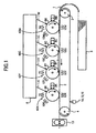
- FIG. 1 shows the composition of a color image forming device in an embodiment of the invention.
- image formation parts 40M, 40C, 40Y and 40K which form images of the respective color components (magenta: M, cyan: C, yellow: Y, black: K) which constitute a color image are arranged sequentially from the upstream side in one row along the transport direction of a transport belt 2 which transports a copy sheet 1.
- the transport belt 2 is an endless belt which is wound between a driven roller 4 which performs follower rotation and a driving roller 3 which performs drive rotation.
- the transport belt 2 is rotated by the driving roller 3 in the direction indicated by the arrow in FIG. 1 .
- the copy sheet 1 which is in the top position among the copy sheets 1 contained in the paper feed tray 5 is supplied at the time of image formation, and it is sucked by the transport belt 2 through electrostatic suction.
- the copy sheet 1 is transported to the first image formation part (magenta) 40M by the transport belt 2, and image formation of magenta is performed therein.
- the first image formation part (magenta) comprises a photoconductor drum 6M, and a charging unit 7M, an exposure unit 8, a development unit 9M, and a photoconductor cleaner 10M which are arranged around the periphery of the photoconductor drum 6M. Since the image formation parts 40C, 40Y and 40K of the other colors have the same component parts as those of the image formation part 40M (magenta) but only the toner images being formed are in different colors, a description thereof will be omitted.
- the photoconductor drum 6M After the surface of the photoconductor drum 6M is uniformly charged by the charging unit 7M, it is exposed to the laser beam 11M corresponding to the image of magenta emitted by the exposure unit 8, so that an electrostatic latent image is formed on the photoconductor surface.
- the laser light is emitted to the photoconductor surface as a scanning light at a predetermined cycle by controlling the light intensity of a LD light source (not shown) in accordance with a line image signal of the main scanning direction.
- the photoconductor drum 6M is moved (or rotated) in the sub-scanning direction which is perpendicular to the main scanning direction so that a scanning exposure of a two-dimensional image is performed by the scanning beam.
- the control of the sub-scanning is carried out based on the control of the motor which rotates the photoconductor drum 6M.
- the electrostatic latent image formed on the photoconductor surface is developed with toner by the development unit 9M, so that a toner image is formed on the photoconductor drum 6M.
- This toner image is transferred to the copy sheet carried on the transport belt 2 by the transfer unit 12M at the position (transfer position) where the transport belt 2 is in contact with the photoconductor drum 6M, so that a monochrome (magenta) image is formed on the copy sheet 1.
- the photoconductor drum 6M after the image transfer is completed is cleaned by the photoconductor cleaner 10M which removes the unnecessary toner remaining on the drum surface, and the photoconductor drum 6M is ready for a next image formation.
- the copy sheet 1 to which the monochrome (magenta) image is transferred by the first image formation part (magenta) 40M is transported to the second image formation part (cyan) 40C by the transport belt 2. Similar to the first image formation part (magenta) 40M, the toner image (cyan) formed on the photoconductor drum 6C is transferred to the copy sheet 1 in a superimposed manner.
- the copy sheet 1 is further transported to the third image formation part (yellow) 40Y and to the fourth image formation part (black) 40K, the formed toner images are similarly transferred to the copy sheet 1, so that a color composite image is formed on the copy sheet 1.
- the copy sheet 1 which is passed through the fourth image formation part 40K and carries a color image formed thereon is separated from the transport belt 2 and subjected to the image fixing by the fixing unit 13.
- the copy sheet is ejected to the outside of the color image forming device.
- the color image forming device of this embodiment is provided with a correction unit which carries out the correction mode using the toner mark detection process, in order to optimize the color image formation operating state and to obtain a high-quality color image.
- the image formation parts 40M, 40C, 40Y and 40K of the respective colors are operated, and the deviation detection toner marks and the optical density detection toner marks are formed on the transport belt 2.
- a change of each of the toner marks is measured based on a change of the characteristic of the image formation parts 40M, 40C, 40Y and 40K of the respective colors, and the image forming device operating state is monitored.
- the toner mark detection sensors 14, 15 and 16 are provided, and a positional deviation and an optical density deviation are detected by using the following detection method.
- the image formation parts 40M, 40C, 40Y and 40K of the respective colors are arranged in one row with the constant pitch "b" in the transport direction of the transport belt. Therefore, in order to superimpose the respective images of the color components formed on the photoconductors, it is necessary to adjust the image writing timing to each photoconductor so that the images of the respective color components may have consistency at the transfer positions on the transport belt 2 which are separated from each other by the pitch "b".
- the operating state is detected, and the operating state is corrected in accordance with the result of the detection. For example, such a change may arise when printing documents more than a predetermined number of sheets is performed, or the image forming device starts operation from the idle state, such as power supply ON, or a temperature change arises which causes the operating state of the device, such as the exposure scanning unit, to change.
- the positional deviation produced between the images of the respective colors is corrected by adjusting the sub-scanning registration, the inclination (skew), the main-scanning registration, and the scanning magnification, respectively.
- the measurement of the toner marks is carried out in order to obtain the correction amounts therefor.
- FIG. 2 shows the arrangement of the sequence of the deviation detection toner marks 17 formed on the transport belt 2 in an embodiment of the invention.
- the mark sequence 17 which includes four lateral lines and four slanting lines of the respective colors arranged at predetermined intervals is set up as one group, and this mark sequence 17 is formed at each of the detection positions of the toner mark detection sensors (which are called sensors) 14, 15 and 16 arranged on the transport 2 at three different positions in the main scanning direction. Namely, at each of the detection positions of the sensors 14, 15 and 16, the toner mark sequence 17 including the set of eight marks is formed, respectively.
- the reason for forming the toner mark sequence 17 including the set of eight marks is to raise the detection accuracy by matching with the position change phase due to a change of the driving speed of the transport belt running in the sub-scanning direction, forming the toner marks in consideration of the phase so that the error in the case of pattern formation and detection may be made as small as possible as shown in FIG. 2 , and computing the average of these detection results.
- the measurement of a skew to the reference color (which is usually K), the sub-scanning registration deviation, the main-scanning registration deviation, and the scanning magnification error is possible by detecting the lateral lines and slanting lines of K, Y, C and M (the set of eight marks) and by using the sensors 14, 15 and 16.
- the image is shifted in the direction opposite to the deviation direction by one half of the maximum amount of deviation detected by the respective sensors, which makes it possible to correct the deviation so that the amount of deviation due to the magnification error in the main scanning direction may not be conspicuous.
- the method of computing the correction amount may be performed by using the known method (for example, see Japanese Laid-Open Patent Application No. 2004-101567 ), and a description thereof will be omitted.
- toner is supplied from the toner cartridge (not shown) to the development units 9M, 9C, 9Y and 9K of the respective colors, respectively.
- the toner thus supplied is transported in one direction from the device back side to the front side, for example (which direction matches with the main scanning line).
- the toner may be in a state where the density of the toner on the device back side is high and the density of the toner on the device front side is low.
- the process control (or electrophotographic process control) is performed on the back side while the toner is in such a state, namely the sensor on the back side of the main scanning line performs optical density detection, then the result of detection of the optical density of an image will be comparatively low as a whole.
- the sensor 15 arranged in the center in the main scanning direction among the sensors 14, 15 and 16 in this example is used for detection shared to the process control. This is because the toner near the center on the main scanning line has a desired in-between density.
- FIG. 3 shows a toner patch sequence 18 for use in the process control which is formed on the transport belt 2 (only the toner patch sequence of K is shown in FIG. 3 ).
- the toner patch sequence 18 two or more marks with different gradations of each of the color components K, C, M and Y are formed on the transport belt 2 only at locations under the sensor 15.
- the setting of a development bias, a charging bias, a laser exposure power, etc. can be performed in the process control, and the optical density of an image can be controlled optimally.
- the sensors 14, 15 and 16 are mounted on the same chip 19 as shown in FIG. 3 . With the arrangement of the plural sensors mounted on the same chip, management of the parts and the chip becomes easy and reduction of the cost can be attained.
- optical density detection toner mark sequence of this example is also applicable to an image forming device which is provided to form a pattern for color matching control, a pattern for photoconductor drive phase control, etc. other than the toner patch for process control mentioned above.
- the correction function that performs the correction mode operation is provided in the control system of the color image forming device.
- this function is to form the above-mentioned toner mark (patch) sequences for both deviation detection and optical density detection on the transport belt 2, measure the formed toner mark (patch) sequences by using the sensors 14, 15 and 16, and perform the correction for optimizing the image formation operating states according to the result of measurement.
- FIG. 4 shows the composition of a control system of the color image forming device in an embodiment of the invention.
- the CPU 27 central processing unit 27, the RAM (random access memory) 28 and the ROM (read-only memory) 29, function as a system control unit which controls the whole image forming device.
- the CPU 27 carries out the control actions for controlling respective component parts including various I/O devices (I/O devices), by using various kinds of control programs and data for the control programs, stored in the RAM 28 or the ROM 29 if needed.
- the control action in the correction mode according to the toner mark detection system is included.
- the control action in the correction mode includes starting operation of the correction mode at predetermined execution timing, and performing operation and processing of the data required for carrying out a series of correction operations including formation of the toner marks, measurement of the toner marks, and adjustment of the setting values according to the result of the measurement.
- the CPU 27 is provided with the data bus 26 and the address bus 30 for exchanging the data, such as the image data being processed and the control data, between the RAM 28 and the ROM 29 and between the various I/O devices via the I/O port 25.
- the writing control unit 32, the laser emission control unit 31, the FIFO (first-in first-out) 24, and the sampling control unit 23 are contained in a part of the various I/O devices.
- the writing control unit 32 is a chip which controls the LD driving plate which drives the LD (laser diode) for exposure which performs the optical writing of images of the respective color components.
- the circuit for executing operation of the normal printing mode and the circuit for executing the correction mode, different from the normal printing mode, which forms the toner marks are provided.
- the sensors 14, 15 and 16 are of the type having a light emission part used for detection of toner marks.
- the laser emission control unit 31 is a device which controls the emission light intensity of each of the light emission parts of the sensors 14, 15 and 16.
- the FIFO 24 and the sampling control unit 23 are devices which are used for acquiring detection data from the sensors 14, 15 and 16.
- the outline of the correction operation which is performed by the CPU 27 of the control system of FIG. 4 in accordance with the instruction codes to the CPU 27 will be explained as follows.
- the toner mark signal detected by the sensor 14 (15, 16) is amplified by the amplifier (AMP) 20.
- the frequency components exceeding the desired frequency are cut off from the amplified toner mark signal by using the filter 21.
- the detection signal which is the analog signal output from the filter 21 is converted into digital data by the A-D converter 22.
- the sampling of data in the A-D converter 22 is controlled by the sampling control unit 23.
- the sampling frequency is 100 kHz.
- the sampled data is stored in the FIFO memory 24 one by one.
- the stored data are transferred via the I/O port 25 to the data bus 26 and further transferred to the CPU 27 and the RAM 28 via the data bus 26.
- various amounts of deviations such as deviations of the toner marks and optical density differences, are calculated, and operation processing for determining the correction amount which optimizes the image formation operating states is performed.
- the CPU 27 Based on the correction amount calculated from the measurement result of the positioning toner marks, the CPU 27 performs the setting of the writing control unit 32 in order to change the image writing frequency based on the change of the sub-scanning/main-scanning registration, the correction of the skew, and a magnification error.
- the writing control unit 32 includes components parts adapted to set up the output frequency in a very fine amount (for example, a clock generator using a voltage-controlled oscillator (VCO)), for the respective colors including the standard color.
- VCO voltage-controlled oscillator
- the process control, the color matching control, and the photoconductor drive phase control are performed, so that an optimized image output can be' obtained.
- the CPU 27 monitors the detection signal output from the sensor 14 (15, 16) at a suitable timing.
- the monitored detection signal is used in order to control the emission light intensity by the laser emission control unit 31, so that a corrected emission light intensity which can perform detection of the toner marks certainly even if degradation of the light emission part of the sensor 14 (15, 16) or the transport belt 2 takes place. Namely, the level of the emission light intensity from the light emission part is always maintained at a constant level.
- the image formation parts 40M, 40C, 40Y and 40K of the respective color components are actually operated on the current setting conditions, and the toner marks are formed on the transport (transfer) belt 2 (see FIG. 2 and FIG. 3 ).
- the toner marks on the transport belt 2 are detected by the sensors 14, 15 and 16.
- the toner marks of each color are formed according to predetermined conditions, so that the deviation (error) from the proper operating state can be obtained as the measuring result.
- the mark sequence including the four lateral lines and four slanting lines of the respective colors arranged at the predetermined intervals is set up, and the plural mark sequences are arranged on the transport belt at the detection positions where the sensors 14, 15 and 16 are provided directly above the detection positions in the main scanning direction.
- the deviation detection toner marks according to the related art are formed on the transport belt the toner marks are formed on the transport belt in the sequence: M-C-Y-K, as shown in FIG. 11 , along the belt transport direction.
- the photoconductor of M arranged in the uppermost position upstream of the belt transport direction is set in the write-enable period in which image formation is possible, and the mark of M is formed in the head-end image formation area on the transport belt.
- the period of the photoconductor pitch "b" is delayed from the start, the photoconductor of C arranged in the second uppermost position upstream of the belt transport direction is set in the write-enable period in which image formation is possible, and the mark of C is formed in the second image formation area on the transport belt.
- the mark of Y is formed in the third image formation area on the transport belt.
- the period "3b" is delayed from the start, and the final mark of K is formed in the last image formation area on the transport belt.
- the total period "4a+3b" is needed from the start of formation of the first mark of M to the end of formation of the last mark of K.
- Correction of the image formation operating states by using the formation of the toner marks is indispensable in order to obtain a quality color image, but the toner mark formation method according to the related art becomes the hindrance of quick document printing, and causes the productivity to be reduced.
- the color image forming device is aimed at improvement of the related art technology in order to shorten the time required for forming the toner marks in the toner mark formation processing at the time of the correction mode.
- One aspect of the present invention that is adopted to enable shortening of the time required for the mark formation is to make the sequence of the color components of the toner marks formed in the sub-scanning direction' different from the sequence of the color components (M-C-Y-K) of the color component images transferred to the transport belt by the transfer units 12M, 12C, 12Y, 12K.
- the color image forming device of the invention shortening the time required is made possible by forming one of the toner marks of the color components, which are in upper positions on the transport belt upstream of the belt transport direction, in the lowermost downstream one of the image formation areas on the transport belt in the belt transport direction.
- FIG. 5 shows an example of the arrangement of image formation areas (K-Y-C-M) on the transport belt to which the toner marks of the respective colors are assigned in an embodiment of the invention.
- This arrangement is a reversal of the arrangement of the image formation parts 40M, 40C, 40Y and 40K in the belt transport direction (see FIG. 1 ).
- K which corresponds to the image formation part 40K arranged in the lowermost downstream position is made into the head-end one, and the area "a" is assigned for each of the respective colors arrayed in the sequence K-Y-C-M, respectively, and the mark of each color is formed therein.
- the mark sequence in the belt transport direction is constituted in this manner.
- the area "a" is similarly assigned to each color, respectively.
- FIG. 6 is a timing chart of the image formation area signals when assigning the toner marks of the respective colors to the mark formation areas shown in FIG. 5 .
- the Low period is the write-enable period in which image formation is possible
- the shaded rectangular signal portion is the period (assigned for image formation) in which the toner mark of the color concerned is formed on the transport belt.
- the sub-scanning (belt transport) is performed at a constant speed, and the period in the timing chart is considered a linear distance (length).
- the image formation area length (or the write-enable period) is represented by "4a" (mm), and one fourth "a” (mm) of the image formation area length is assigned for each of the respective colors M, C, Y and K, as the shaded rectangular signal portion.
- the image formation area signal of M whose photoconductor is in the uppermost upstream position, is set to the write-enable period.
- any of the image formation area signals of C, Y and K, whose photoconductors are in the lower downstream positions, is set to the write-enable period sequentially one by one.
- the write-enable period of 4a for each color is secured, and the write-enable periods which are the same as those in the normal printing mode are secured.
- the write-enable period of M which corresponds to the image formation part 40M in the uppermost upstream position on the transport belt 2, arises.
- the last one-fourth part of this write-enable period of M is assigned for the mark writing area of "a", and the mark writing of M is performed last.
- the write-enable period of C arranged following M, in the transport direction of the transport belt 2, arises. And the third one-fourth part of the write-enable period of C is assigned for the mark writing area of "a", and the mark writing of C is performed.
- the period of 3b is delayed from the start, and writes the mark of K in the area of the head of the write-enable period one by one.
- the write-enable period of M is set to the head-end one, and the total period "4a+3b" is required from the start of the write-enable period of M to the end of the write-enable period of K.
- the following embodiment is adapted to deactivate the image writing of the respective colors at the end of mark formation operation when the sequence of the color components of the toner marks in the sub-scanning direction is a reversal of the sequence of the color components of the color component images transferred by the image formation parts in the sub-scanning direction, similar to the above-mentioned embodiment ( FIG. 6 ), thereby shortening the time required.
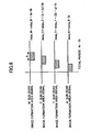
- FIG. 7 is a timing chart of the image formation area signals for explaining mark formation operation (a>b) which deactivates the image writing of the respective colors at the end of mark formation operation.
- the M mark image is formed last (when a ⁇ b, however, the C or Y mark image is formed last).
- the time required is a period between the start of the write-enable period of M and the end of the write-enable period of M, and this period is equivalent to "4a" as shown in FIG. 7 .
- the time required can be shortened by a time equivalent to 3b when compared with the related art.
- the time required can be shortened when compared with "4a+3b" in the case of the related art.
- the following embodiment is adapted to eliminate the precondition for securing the write-enable periods which are the same as those of the normal printing mode as in the previously described embodiment ( FIG. 6 ), thereby shortening the time required.
- the write-enable period of 4a is secured for each of the color components M, C, Y and K, and the write-enable periods of M, C, Y and K are delayed each other by a time equivalent to the pitch b. This is the precondition for securing the write-enable periods which are the same as those of the normal printing mode.
- the non-writing period in which writing operation of the mark image is not performed will be produced at the time of start of the mark formation operation of each color. Even if the non-writing period is deleted, the mark formation operation in the correction mode is not affected.
- FIG. 8 is a timing chart of the image formation area signals in which the non-writing periods produced at the start of mark formation operation are deleted from the timing chart of FIG. 7 .
- the color of the mark image which is formed earliest is K which is arranged at the head-end one of the mark formation areas.
- the condition a>b is satisfied and the sequence of the color components of the toner marks in the sub-scanning direction is a reversal of the sequence of the color components of the color component images transferred by the image formation parts in the sub-scanning direction.
- the mark images of other colors are not formed until the mark image of K is formed following the start of mark formation operation. That is, the period 3b (which is set up as the delay time of K in FIG. 7 ) is deleted from the total period, and the start time for mark formation of each color is brought forward by a time equivalent to 3b.
- FIG. 8 shows this result.
- the formation of the mark image of K is started immediately when the mark formation operation is started.
- the mark formation operation is completed.
- the time required is set to "4a-3b". In this embodiment, the time required can be further shortened by a time equivalent to 3b when compared with the example of FIG. 7 .
- the following embodiment is adapted to delete the non-writing periods produced at the time of start of mark formation operation, thereby shortening the time required.
- the sequence of the color components of the toner marks in the sub-scanning direction is a reversal of the sequence of the color components of the color component images transferred by the image formation parts in the sub-scanning direction, which is the same as the case in the previous embodiment ( FIG. 8 ).
- the condition a ⁇ b is satisfied, which is a reversal of the relation between "a" and "b" in the case of the previous embodiment ( FIG. 8 ).
- FIG. 9 is a timing chart of the image formation area signals for explaining the mark formation operation (a ⁇ b) which deactivates the image writing of the respective colors.
- the non-writing periods produced at the start of mark formation operation are not yet deleted.
- the M mark image is formed earliest.
- the mark images of other colors are not formed until the formation of the M mark image is completed following the start of the mark formation operation. That is, the period 3a (which is set up to assign the last mark formation area) is deleted from the total period, and the start time for mark formation of each color is brought forward by a time equivalent to 3a.
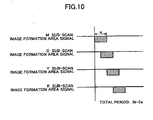
- FIG. 10 shows this result.
- the formation of the mark image of M is started immediately when the mark formation operation is started, and at the time of end of formation of the K mark image of the last timing, the mark formation operation is completed.
- the time required is set to "3b-2a". In this embodiment, the time required can be further shortened by a time equivalent to 3a when compared with the example of FIG. 9 .
Landscapes
- Physics & Mathematics (AREA)
- General Physics & Mathematics (AREA)
- Engineering & Computer Science (AREA)
- Microelectronics & Electronic Packaging (AREA)
- Color Electrophotography (AREA)
- Control Or Security For Electrophotography (AREA)
- Laser Beam Printer (AREA)
Claims (9)
- Dispositif de formation d'image en couleur comprenant :une pluralité de premiers mécanismes de support d'image (6M, 6C, 6Y, 6K) de composantes de couleur (40M, 40C, 40Y, 40K) respectives conçus chacun pour supporter une image de composante de couleur sur une surface photoconductrice, respectivement ;une unité d'exposition à balayage (8) conçue pour appliquer un faisceau lumineux de balayage, généré conformément à un signal d'image de ligne d'une direction de balayage principal, à chacune des surfaces photoconductrices des composantes de couleur des premiers moyens de support d'image selon un cycle prédéterminé alors que les surfaces photoconductrices sont déplacées dans une direction de balayage secondaire perpendiculaire à la direction de balayage principal, de sorte qu'une image de composante de couleur bidimensionnelle soit formée sur chaque surface photoconductrice par une exposition au faisceau lumineux de balayage ;un deuxième moyen de support d'image (2) conçu pour recevoir les images de composante de couleur transférées par lesdits premiers moyens de support d'image pour supporter une image composite en couleur produite par les images de composante de couleur reçues ;une unité de transport de deuxième moyen de support d'image (3, 4) conçue pour transporter le deuxième moyen de support d'image dans une direction de transport principale à travers des positions de transfert d'image des composantes de couleur (40M, 40C, 40Y, 40K) respectives en synchronisation avec le déplacement des premiers moyens de support d'image des composantes de couleur respectives dans la direction de balayage secondaire ;lesdites composantes de couleur (40M, 40C, 40Y, 40K) sont agencées le long de ladite direction de transport principale dudit deuxième moyen de support d'image dans un ordre spécifique, moyennant quoi la composante de couleur à la position la plus en amont le long de la direction de transport principale est désignée par (40M) et la composante de couleur à la position la plus en aval le long de la direction de transport principale est désignée par (40K) ;une unité de transfert (12M, 12C, 12Y, 12K) conçue pour transférer les images de composante de couleur des premiers moyens de support d'image des composantes de couleur au deuxième moyen de support d'image ;une unité de formation d'image de motif de correction conçue pour commander l'unité d'exposition à balayage pour former des images de motif de correction, chacune étant conçue pour corriger des états d'opération de formation d'image pour la composante de couleur concernée, dans des zones prédéterminées (M, C, Y, K) attribuées à chacune des couleurs respectives et disposées sur le deuxième moyen de support d'image le long de ladite direction de transport principale ;lesdites zones prédéterminées (M, C, Y, K) sont agencées sur ledit deuxième moyen de support d'image le long de ladite direction de transport principale dans un ordre spécifique, moyennant quoi la zone prédéterminée à la position la plus en amont le long de la direction de transport principale est désignée par (M) et la zone prédéterminée à la position la plus en aval le long de la direction de transport principale est désignée par (K) ;une unité de mesure de motif (14, 15, 16) conçue pour mesurer les images de motif de correction formées sur le deuxième moyen de support d'image par l'unité de formation d'image de motif de correction ;une unité de commande conçue pour corriger les états d'opération de formation d'image pour les composantes de couleur respectives conformément à un résultat de la mesure de l'unité de mesure de motif pour commander une opération de formation d'image du dispositif de formation d'image en couleur,ledit dispositif de formation d'image en couleur étant caractérisé en ce que l'unité de formation d'image de motif de correction est agencée de sorte que, lorsqu'une longueur a de chacune des images de motif de correction est supérieure à un pas b entre deux moyens adjacents parmi la pluralité de premiers moyens de support d'image, à une extrémité de formation d'une image de motif de correction sur le premier moyen de support d'image de la composante de couleur à la position la plus en amont le long de la direction de transport principale et désignée par (40M), des signaux de validation d'écriture pour former des images de motif de correction sur les premiers moyens de support d'image des autres composantes de couleur désignées par (40C), (40Y), (40K) soient désactivés, et, lorsqu'une longueur a de chacune des images de motif de correction est inférieure à un pas b entre deux moyens adjacents parmi la pluralité de premiers moyens de support d'image, à une extrémité de formation d'une image de motif de correction sur le premier moyen de support d'image de la composante de couleur à la position la plus en aval le long de la direction de transport principale et désignée par (40K), des signaux de validation d'écriture pour former des images de motif de correction sur les premiers moyens de support d'image des autres composantes de couleur désignées par (40M), (40C), (40Y) soient désactivés.
- Dispositif de formation d'image en couleur selon la revendication 1, dans lequel l'unité de formation d'image de motif de correction est configurée pour débuter un traitement de formation des images de motif de correction sur le deuxième moyen de support d'image immédiatement lorsque la première image parmi les images de composante de couleur correspondant aux images de motif de correction est formée sur l'un correspondant des premiers moyens de support d'image.
- Dispositif de formation d'image en couleur selon la revendication 1 ou 2, dans lequel l'unité de formation d'image de motif de correction est configurée de sorte qu'une séquence des composantes de couleur des images de motif de correction formées par l'unité de formation d'image de motif de correction dans la direction de balayage secondaire soit l'inverse d'une séquence des composantes de couleur des images de composante de couleur transférées par l'unité de transfert dans la direction de balayage secondaire.
- Dispositif de formation d'image en couleur selon la revendication 3, dans lequel, lorsqu'une longueur a de chacune des images de motif de correction est supérieure à un pas b entre deux moyens adjacents parmi la pluralité de premiers moyens de support d'image, un traitement de formation des images de motif de correction pour chacune des composantes de couleur est débuté plus tôt que dans un mode d'impression normal d'un temps équivalent à

- Dispositif de formation d'image en couleur selon la revendication 3, dans lequel, lorsqu'une longueur de chacune des images de motif de correction est inférieure à un pas b entre deux moyens adjacents parmi la pluralité de premiers moyens de support d'image, le traitement de formation des images de motif de correction pour chacune des composantes de couleur est débuté plus tôt que dans un mode d'impression normal d'un temps équivalent à

- Dispositif de formation d'image en couleur selon l'une quelconque des revendications 1 à 5, dans lequel l'unité de formation d'image de motif de correction est configurée pour terminer un traitement de formation des images de motif de correction immédiatement lorsqu'une image finale parmi les images de motif de correction est formée sur le deuxième moyen de support d'image.
- Dispositif de formation d'image en couleur selon l'une quelconque des revendications 1 à 6, dans lequel les images de motif de correction sont utilisées pour la correction de conditions de processus de formation d'image.
- Dispositif de formation d'image en couleur selon l'une quelconque des revendications 1 à 7, dans lequel les images de motif de correction sont utilisées pour la correction de conditions de correspondance de couleurs de chaque composante de couleur.
- Dispositif de formation d'image en couleur selon l'une quelconque des revendications 1 à 8, dans lequel les images de motif de correction sont utilisées pour une correction des conditions de phase de commande du premier moyen de support d'image de chaque composante de couleur.
Applications Claiming Priority (1)
| Application Number | Priority Date | Filing Date | Title |
|---|---|---|---|
| JP2005222813A JP2007041128A (ja) | 2005-08-01 | 2005-08-01 | カラー画像形成装置 |
Publications (2)
| Publication Number | Publication Date |
|---|---|
| EP1750180A1 EP1750180A1 (fr) | 2007-02-07 |
| EP1750180B1 true EP1750180B1 (fr) | 2012-10-17 |
Family
ID=37405361
Family Applications (1)
| Application Number | Title | Priority Date | Filing Date |
|---|---|---|---|
| EP06254042A Ceased EP1750180B1 (fr) | 2005-08-01 | 2006-08-01 | Dispositif de formation d'images en couleur |
Country Status (3)
| Country | Link |
|---|---|
| US (1) | US7715768B2 (fr) |
| EP (1) | EP1750180B1 (fr) |
| JP (1) | JP2007041128A (fr) |
Families Citing this family (6)
| Publication number | Priority date | Publication date | Assignee | Title |
|---|---|---|---|---|
| JP4591517B2 (ja) * | 2008-01-30 | 2010-12-01 | ブラザー工業株式会社 | 画像形成装置 |
| JP5181753B2 (ja) * | 2008-03-18 | 2013-04-10 | 株式会社リコー | カラー画像形成装置、位置ずれ補正方法、位置ずれ補正プログラム、及び記録媒体 |
| JP5750850B2 (ja) * | 2010-09-21 | 2015-07-22 | 富士ゼロックス株式会社 | 画像読み取り装置および画像形成装置 |
| JP2014056188A (ja) | 2012-09-13 | 2014-03-27 | Ricoh Co Ltd | 画像形成装置、画像調整方法、プログラム、およびコンピュータ読み取り可能な記憶媒体 |
| JP6015311B2 (ja) * | 2012-09-28 | 2016-10-26 | 富士ゼロックス株式会社 | 画像形成装置およびプログラム |
| JP6335639B2 (ja) | 2014-05-21 | 2018-05-30 | キヤノン株式会社 | 画像形成装置及び画像形成方法 |
Family Cites Families (23)
| Publication number | Priority date | Publication date | Assignee | Title |
|---|---|---|---|---|
| JPH0719085B2 (ja) | 1986-09-17 | 1995-03-06 | 株式会社リコー | デジタルカラ−画像形成装置 |
| JP3530551B2 (ja) | 1993-07-01 | 2004-05-24 | 富士重工業株式会社 | 多気筒エンジンの燃料噴射制御方法 |
| JPH07219303A (ja) | 1994-02-07 | 1995-08-18 | Konica Corp | カラー画像形成装置 |
| JP3514398B2 (ja) * | 1994-12-07 | 2004-03-31 | 株式会社リコー | 画像形成装置 |
| JP3527352B2 (ja) * | 1996-02-26 | 2004-05-17 | 株式会社リコー | カラ−画像形成装置 |
| JPH10198110A (ja) * | 1996-11-18 | 1998-07-31 | Ricoh Co Ltd | カラー画像形成方法 |
| JP3661328B2 (ja) | 1997-01-29 | 2005-06-15 | 富士ゼロックス株式会社 | 画像形成装置 |
| JP2000318221A (ja) * | 1999-05-14 | 2000-11-21 | Ricoh Co Ltd | 画像形成装置 |
| JP4149627B2 (ja) * | 1999-10-18 | 2008-09-10 | 株式会社リコー | カラー画像形成装置 |
| JP2001166553A (ja) * | 1999-12-13 | 2001-06-22 | Ricoh Co Ltd | カラー画像形成装置 |
| US6573918B2 (en) * | 2000-08-22 | 2003-06-03 | Ricoh Company, Ltd. | Image forming apparatus having a plurality of image data interfaces |
| JP2003084530A (ja) * | 2001-09-14 | 2003-03-19 | Ricoh Co Ltd | カラー画像形成装置 |
| JP3640629B2 (ja) * | 2001-09-21 | 2005-04-20 | 株式会社リコー | カラー画像形成装置 |
| JP3644923B2 (ja) * | 2001-12-18 | 2005-05-11 | 株式会社リコー | カラー画像形成方法及びカラー画像形成装置 |
| JP2004069909A (ja) | 2002-08-05 | 2004-03-04 | Canon Inc | カラー画像形成装置 |
| JP3773884B2 (ja) * | 2002-09-04 | 2006-05-10 | 株式会社リコー | 画像形成装置 |
| JP2004117896A (ja) | 2002-09-26 | 2004-04-15 | Konica Minolta Holdings Inc | 画像形成装置及び画像形成方法 |
| JP2005031263A (ja) * | 2003-07-09 | 2005-02-03 | Ricoh Co Ltd | 画像形成装置 |
| JP2005077469A (ja) * | 2003-08-28 | 2005-03-24 | Ricoh Co Ltd | 画像形成装置 |
| EP1575258A3 (fr) * | 2004-03-09 | 2007-12-05 | Ricoh Company, Ltd. | Appareil de formation d'image, méthode pour le contrôler, ordinateur, et cartouche de traitement |
| JP2005300953A (ja) * | 2004-04-13 | 2005-10-27 | Ricoh Co Ltd | カラー画像形成装置、その駆動制御方法及び駆動制御用プログラム |
| JP2006208639A (ja) * | 2005-01-27 | 2006-08-10 | Ricoh Co Ltd | 画像形成装置、プリンタ装置、ファクシミリ装置及び複写機 |
| US7609987B2 (en) * | 2005-05-17 | 2009-10-27 | Canon Kabushiki Kaisha | Image forming apparatus and control method of image forming apparatus |
-
2005
- 2005-08-01 JP JP2005222813A patent/JP2007041128A/ja active Pending
-
2006
- 2006-08-01 US US11/496,510 patent/US7715768B2/en not_active Expired - Fee Related
- 2006-08-01 EP EP06254042A patent/EP1750180B1/fr not_active Ceased
Also Published As
| Publication number | Publication date |
|---|---|
| EP1750180A1 (fr) | 2007-02-07 |
| US20070025779A1 (en) | 2007-02-01 |
| JP2007041128A (ja) | 2007-02-15 |
| US7715768B2 (en) | 2010-05-11 |
Similar Documents
| Publication | Publication Date | Title |
|---|---|---|
| US8848238B2 (en) | Optical writing control device, image forming apparatus, and optical writing control method for controlling the light emitting timing of a light source | |
| US7952774B2 (en) | Image forming apparatus, image formation control method, and computer program product | |
| US7817947B2 (en) | Image forming apparatus and correction method of color-misregistration in an image | |
| EP1496403B1 (fr) | Appareil de formation d'images en couleur avec un procédé de correction d'erreur de position | |
| JP3606029B2 (ja) | 画像形成装置 | |
| US20090080915A1 (en) | Color image forming apparatus and color misregistration correction method therefor | |
| JP3489595B2 (ja) | 多重画像形成装置の画像サンプリング及び色ずれ補正方式 | |
| CN101196714A (zh) | 图像形成装置 | |
| JP5712971B2 (ja) | 画像処理装置、画像処理方法および印刷システム | |
| US8862002B2 (en) | Image forming apparatus and method | |
| JP2007286176A (ja) | 画像形成装置、画像形成制御方法及びプログラム | |
| JP4869692B2 (ja) | 画像形成装置、色ずれ補正方法および色ずれ補正プログラム | |
| US7382390B2 (en) | Image forming apparatus and control method thereof having main scan length correcting feature | |
| EP1750180B1 (fr) | Dispositif de formation d'images en couleur | |
| JP5005221B2 (ja) | 画像形成装置、画像形成方法、プログラム及びコンピュータ読取可能な記録媒体 | |
| JP4131313B2 (ja) | 画像出力装置の制御装置及びこれを用いた画像形成装置 | |
| JP6750863B2 (ja) | 画像形成装置 | |
| JP2004188665A (ja) | 画像形成装置、補正データ生成装置および光プリントヘッドの光量補正方法 | |
| US9201331B2 (en) | Image forming apparatus, image correcting method, computer readable storage medium, image correction unit and image forming system | |
| US20090225342A1 (en) | Image forming apparatus | |
| JP2012053190A (ja) | 光書き込み装置、画像形成装置、および光書き込み制御方法 | |
| JP2014021242A (ja) | 画像形成装置及び画像形成方法 | |
| JP2002267970A (ja) | 画像形成装置 | |
| JP2007108283A (ja) | 画像形成装置及び色ずれ補正方法 | |
| JP4849878B2 (ja) | 位置ずれ補正方法及びカラー画像形成装置 |
Legal Events
| Date | Code | Title | Description |
|---|---|---|---|
| PUAI | Public reference made under article 153(3) epc to a published international application that has entered the european phase |
Free format text: ORIGINAL CODE: 0009012 |
|
| 17P | Request for examination filed |
Effective date: 20060807 |
|
| AK | Designated contracting states |
Kind code of ref document: A1 Designated state(s): AT BE BG CH CY CZ DE DK EE ES FI FR GB GR HU IE IS IT LI LT LU LV MC NL PL PT RO SE SI SK TR |
|
| AX | Request for extension of the european patent |
Extension state: AL BA HR MK YU |
|
| 17Q | First examination report despatched |
Effective date: 20070420 |
|
| AKX | Designation fees paid |
Designated state(s): DE ES FR GB IT NL |
|
| GRAP | Despatch of communication of intention to grant a patent |
Free format text: ORIGINAL CODE: EPIDOSNIGR1 |
|
| GRAJ | Information related to disapproval of communication of intention to grant by the applicant or resumption of examination proceedings by the epo deleted |
Free format text: ORIGINAL CODE: EPIDOSDIGR1 |
|
| GRAP | Despatch of communication of intention to grant a patent |
Free format text: ORIGINAL CODE: EPIDOSNIGR1 |
|
| GRAS | Grant fee paid |
Free format text: ORIGINAL CODE: EPIDOSNIGR3 |
|
| GRAA | (expected) grant |
Free format text: ORIGINAL CODE: 0009210 |
|
| AK | Designated contracting states |
Kind code of ref document: B1 Designated state(s): DE ES FR GB IT NL |
|
| REG | Reference to a national code |
Ref country code: GB Ref legal event code: FG4D |
|
| REG | Reference to a national code |
Ref country code: DE Ref legal event code: R096 Ref document number: 602006032484 Country of ref document: DE Effective date: 20121213 |
|
| REG | Reference to a national code |
Ref country code: NL Ref legal event code: VDEP Effective date: 20121017 |
|
| PG25 | Lapsed in a contracting state [announced via postgrant information from national office to epo] |
Ref country code: NL Free format text: LAPSE BECAUSE OF FAILURE TO SUBMIT A TRANSLATION OF THE DESCRIPTION OR TO PAY THE FEE WITHIN THE PRESCRIBED TIME-LIMIT Effective date: 20121017 Ref country code: ES Free format text: LAPSE BECAUSE OF FAILURE TO SUBMIT A TRANSLATION OF THE DESCRIPTION OR TO PAY THE FEE WITHIN THE PRESCRIBED TIME-LIMIT Effective date: 20130128 |
|
| PLBE | No opposition filed within time limit |
Free format text: ORIGINAL CODE: 0009261 |
|
| STAA | Information on the status of an ep patent application or granted ep patent |
Free format text: STATUS: NO OPPOSITION FILED WITHIN TIME LIMIT |
|
| PG25 | Lapsed in a contracting state [announced via postgrant information from national office to epo] |
Ref country code: IT Free format text: LAPSE BECAUSE OF FAILURE TO SUBMIT A TRANSLATION OF THE DESCRIPTION OR TO PAY THE FEE WITHIN THE PRESCRIBED TIME-LIMIT Effective date: 20121017 |
|
| 26N | No opposition filed |
Effective date: 20130718 |
|
| REG | Reference to a national code |
Ref country code: DE Ref legal event code: R097 Ref document number: 602006032484 Country of ref document: DE Effective date: 20130718 |
|
| REG | Reference to a national code |
Ref country code: FR Ref legal event code: PLFP Year of fee payment: 11 |
|
| REG | Reference to a national code |
Ref country code: FR Ref legal event code: PLFP Year of fee payment: 12 |
|
| REG | Reference to a national code |
Ref country code: FR Ref legal event code: PLFP Year of fee payment: 13 |
|
| PGFP | Annual fee paid to national office [announced via postgrant information from national office to epo] |
Ref country code: FR Payment date: 20180827 Year of fee payment: 13 Ref country code: DE Payment date: 20180823 Year of fee payment: 13 |
|
| PGFP | Annual fee paid to national office [announced via postgrant information from national office to epo] |
Ref country code: GB Payment date: 20180822 Year of fee payment: 13 |
|
| REG | Reference to a national code |
Ref country code: DE Ref legal event code: R119 Ref document number: 602006032484 Country of ref document: DE |
|
| GBPC | Gb: european patent ceased through non-payment of renewal fee |
Effective date: 20190801 |
|
| PG25 | Lapsed in a contracting state [announced via postgrant information from national office to epo] |
Ref country code: FR Free format text: LAPSE BECAUSE OF NON-PAYMENT OF DUE FEES Effective date: 20190831 Ref country code: DE Free format text: LAPSE BECAUSE OF NON-PAYMENT OF DUE FEES Effective date: 20200303 |
|
| PG25 | Lapsed in a contracting state [announced via postgrant information from national office to epo] |
Ref country code: GB Free format text: LAPSE BECAUSE OF NON-PAYMENT OF DUE FEES Effective date: 20190801 |