EP1750192A1 - Steuerung eines aktiven Schwingungsisolationssystems - Google Patents
Steuerung eines aktiven Schwingungsisolationssystems Download PDFInfo
- Publication number
- EP1750192A1 EP1750192A1 EP05017138A EP05017138A EP1750192A1 EP 1750192 A1 EP1750192 A1 EP 1750192A1 EP 05017138 A EP05017138 A EP 05017138A EP 05017138 A EP05017138 A EP 05017138A EP 1750192 A1 EP1750192 A1 EP 1750192A1
- Authority
- EP
- European Patent Office
- Prior art keywords
- control
- digital
- signals
- vibration isolation
- sensor
- Prior art date
- Legal status (The legal status is an assumption and is not a legal conclusion. Google has not performed a legal analysis and makes no representation as to the accuracy of the status listed.)
- Granted
Links
- 238000002955 isolation Methods 0.000 title claims abstract description 31
- 239000011159 matrix material Substances 0.000 claims abstract description 14
- 238000003491 array Methods 0.000 claims abstract description 4
- 230000035945 sensitivity Effects 0.000 claims abstract description 3
- 238000004364 calculation method Methods 0.000 claims description 13
- 230000001629 suppression Effects 0.000 claims description 3
- 230000008859 change Effects 0.000 claims description 2
- 230000033228 biological regulation Effects 0.000 abstract description 6
- 238000005070 sampling Methods 0.000 description 10
- 230000006870 function Effects 0.000 description 7
- 230000008901 benefit Effects 0.000 description 4
- 235000019800 disodium phosphate Nutrition 0.000 description 4
- 230000005284 excitation Effects 0.000 description 3
- 230000001419 dependent effect Effects 0.000 description 2
- 229910000831 Steel Inorganic materials 0.000 description 1
- 238000007792 addition Methods 0.000 description 1
- 230000005540 biological transmission Effects 0.000 description 1
- 238000006243 chemical reaction Methods 0.000 description 1
- 230000001276 controlling effect Effects 0.000 description 1
- 238000010586 diagram Methods 0.000 description 1
- 239000000284 extract Substances 0.000 description 1
- 238000001914 filtration Methods 0.000 description 1
- 238000000034 method Methods 0.000 description 1
- 239000002243 precursor Substances 0.000 description 1
- 230000008569 process Effects 0.000 description 1
- 230000001105 regulatory effect Effects 0.000 description 1
- 230000003252 repetitive effect Effects 0.000 description 1
- 230000004044 response Effects 0.000 description 1
- 238000001228 spectrum Methods 0.000 description 1
- 239000010959 steel Substances 0.000 description 1
- 238000011144 upstream manufacturing Methods 0.000 description 1
Images
Classifications
-
- F—MECHANICAL ENGINEERING; LIGHTING; HEATING; WEAPONS; BLASTING
- F16—ENGINEERING ELEMENTS AND UNITS; GENERAL MEASURES FOR PRODUCING AND MAINTAINING EFFECTIVE FUNCTIONING OF MACHINES OR INSTALLATIONS; THERMAL INSULATION IN GENERAL
- F16F—SPRINGS; SHOCK-ABSORBERS; MEANS FOR DAMPING VIBRATION
- F16F15/00—Suppression of vibrations in systems; Means or arrangements for avoiding or reducing out-of-balance forces, e.g. due to motion
- F16F15/002—Suppression of vibrations in systems; Means or arrangements for avoiding or reducing out-of-balance forces, e.g. due to motion characterised by the control method or circuitry
Definitions
- the invention relates to a control of an active vibration isolation system comprising a number of vibration transducers for providing analog sensor signals, a number of vibration suppression actuators and a control unit for processing the sensor signals into actuator control signals.
- Such controllers are constructed in the form of a control loop ( EP-A 0 621 418 . US Pat. No. 5,423,523 . US Pat. No. 5,734,246 ), where the control unit operates either on the analog or on the digital level.
- the advantage of signal processing on an analogue level is the achievable faster response time to disturbances acting on the vibration isolation system compared to signal processing in a digital control unit. This is caused by the double conversion analog-digital as well as digital-analogue and by the sampling rate and the computing time within the sampling rate, which leads to an additional signal propagation time.
- the sampling rate can only be increased to the extent that all control algorithms can be processed within a sampling period. In practice, therefore, the complexity of the control algorithm together with the computing power of the digital signal processor (DSP) determines the maximum possible sampling rate and thus the shortest possible signal propagation time.
- DSP digital signal processor
- a digitally operating control unit again has significant advantages in terms of good configurability, control options by means of a PC computer and adaptability to changing system conditions.
- the invention is therefore based on the object to provide a control of an active vibration isolation system using a control unit that operates on a digital level, but in which the additional signal propagation time remains moderate.
- an FPGA system made up of "Field Programmable Gate Arrays" is used as the control unit, which is preceded by an analog-to-digital converter and connected downstream of a digital-to-analog converter.
- the FPGA system is a subsystem.
- the FPGA system contains a sensor control matrix, which uses the sensor signals to form the axis signals assigned to the six degrees of freedom.
- the axis signals are each further processed in control cascades to provide axis output signals.
- actuator setting signals are obtained from the axis output signals.
- the initially digital actuator actuator signals are converted by an output-side digital-to-analog converter into analog actuator control signals.
- axis signals there are six degrees of freedom to consider, that is, six axis signals are to be calculated, and for this purpose the sensor control matrix multiplies 6 sensor values with a 6x6 matrix.
- the axis signals thus generated generally have to be further processed by filtering in order to generate actuating signals at the actuator. Therefore, six independent control cascades are provided for the six axis signals.
- the control cascades preferably each contain five biquad filters in each row. This high- or low-pass or other filter properties can be realized.
- control device is mainly a digital signal processor DSP into consideration, as it is similar already used in known regulations of active vibration isolation systems.
- DSP digital signal processors
- the DSP control device is expediently located both at the sensor buffer and at the actuator buffer connected to access the control system.
- the sampling rate of the DSP controller will be lower than the clock rate encountered in the FPGA system. This opens up the possibility of running regulations with a high requirement for the lowest possible phase loss on the FPGA system, but allowing other regulations to be calculated on the DSP control device. Because of the connection to the actuator buffer, signal summation can occur in this actuator buffer, regardless of how fast the data comes in from the DSP controller side. In particular, the closed-loop system of the FPGA subsystem is not affected by the additional data of the DSP control device.
- the digital signal processor DSP or another such digital signal processor DSP can also be connected to at least one of the biquad filters in order to be able to change its coefficients if necessary. In this way, the vibration isolation system can quickly adapt to changing basic conditions.
- Each control cascade may have multiple biquad filters, it being convenient to assign an output buffer to each biquad filter from which a subsequent biquad filter may serve.
- another signal processor DSP can be connected for diagnostic purposes.
- the digital signal processor is connected to the actuator buffer, it can also contribute additional digital actuator control signals.
- the digital signal processor can also contribute additional digital actuator control signals.
- This vibration isolation system supports a mass to be insulated from a footprint and includes a set of passive isolation elements (spring / damper combinations of rubber, air springs, steel springs, and the like) and active elements , for example, controlled in push-pull to the vibrational excitation of the mass
- Such active vibration isolation systems include a number of Vibration sensor or sensors 2 for the supply of analog sensor signals and a number of actuators 3 for vibration suppression of the mass.
- the vibration signal transmitters or sensors 2 are arranged in a specific manner adapted to the intended use around the mass to be insulated, also with regard to their directional sensitivity.
- the actuators 3 are also suitably arranged to the mass to support them and to isolate the vibration of the mass from the environment or to counteract such vibrations.
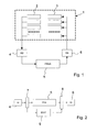
- the sensors 2 and the actuators 3 are connected via a controller which contains a FPGA subsystem 5 of freely programmable gate arrays as a control unit.
- the FPGA subsystem operates purely digitally, which is why it has its input side an analog-to-digital converter 4 for converting the analog sensor signals into digital sensor signals and the output side a digital-to-analog converter for converting the digital into analog actuator control signals are switched on.
- the components 2, 4, 5, 6, 3 thus form a feedback loop of the controller.
- FPGAs are programmable memory devices that have a matrix of calculation elements and whose functionality is determined by configuration bits. These calculation elements, also referred to as logic blocks, are linked together via a plurality of wiring channels. In addition, all internal resources are surrounded by programmable I / O blocks. This allows specific circuits to be implemented in FPGAs, whose logical functions are mapped in the logic blocks and whose results, linked together, realize the entire circuit.
- FIG. 2 shows an extension of the scheme of FIG. 1 omitting the sensors 2 and the actuators 3.
- a sensor buffer 7 is connected and connected between the output of the FPGA subsystem.
- Subsystem and the digital-to-analog converter 6 an actuator buffer 8 connected.
- a digital signal processor DSP 9 is arranged parallel to the FPGA subsystem.
- Digital signal processors are microprocessors that are tailored to the tasks in the field of digital signal processing.
- the code for DSPs includes many arithmetic operations, especially multiplications and additions. There are few branches, if you have, then very well predictable jump targets.
- DSPs have a high concurrency and process very large amounts of data.
- the C programming language has also become standard in DSPs, but time-critical subprograms are to be programmed in assembler. Because most signal processing systems use complex mathematical operations on time-critical (real-time) signals, DSPs have adapted architectures to accelerate repetitive, numerically-complex calculations.
- the FPGA subsystem is used to form the control signals for vibration isolation, while other controls are handled by the DSP system.
- This can access the data of the control system via the sensor buffer 7 and the actuator buffer 8, but is not dependent on the clocking of the FPGA subsystem in the choice of the sampling rate.
- Regulations with high demands the least possible phase loss (control delay) is computed on the FPGA subsystem, while other controls, such as those that occur after shifting the isolatable mass of the vibration isolation system from one location to another on a machine bed or the like, are calculated by the DSP system , At the actuator buffer 8, a summation of the calculated values of the two systems takes place.
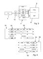
- Fig. 3 shows the structure of the sensor buffer 7.
- a RAM memory is used with areas 71, 72, 73, 730 for individual sensors.
- an FPGA module 10 is expediently used.
- the individual sensor memory areas 71, 72, 73, 730 can be accessed both by the FPGA subsystem 5 and by the DSP system 9. As already explained, this is done independently of each other with a different sampling rate.
- Fig. 4 shows the internal structure of the FPGA subsystem.
- the axis signals are processed in the control cascade block 53 to axis output signals, namely for each axis signal 521 to 526 each a control cascade with five biquad filters 531, 532, 533, 534 and 535 are provided, which are connected in series and IIR- Represent second-order filters.
- a fixed calculation rule is implemented with coefficients that are freely adjustable via an FPGA memory, not shown.
- the result of the first biquad 531 in the series is fed to the next biquad 532 as an input.
- biquad is a two-pole zeroing filter and consists of five coefficients. There are several implementations for this filter. The embodiment presented here corresponds to the so-called direct-form-I representation.
- H z b 0 + b 1 ⁇ z - 1 + b 2 ⁇ z - 2 1 + a 1 ⁇ z - 1 + a 2 ⁇ z - 2
- y (n) a 1 y (n-1) + a 2 y (n-2) + b 0 x (n) + b 1 x (n-1) + b 2 x (n-2)
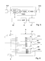
- FIG. 5 shows a schematic overview of a biquad 532 and the data access by a DSP system 9.
- a biquad is connected to a computation precursor, which is here assumed to be the biquad 531.
- a computational successor is connected to the biquad 532, here the biquad 533.
- the biquad 532 contains an input sample stage 5321 for input samples x and an excitation sample stage 5322 for excitation signals n.
- the stage 5322 forms a summation input and provides an additional input bin for each biquad and allows diagnostic signals, e.g. As noise or sine, feed into the biquad.
- the input sample x for each biquad is thus composed of the applied input sample and an optional additional diagnostic sample.
- the diagnostic sample is provided by the DSP system 9, but it is possible that the diagnostic sample is a noise / sine signal sample generated by the FPGA system itself.
- the stages 5321 and 5322 are summed in a summation stage 5323 and supplied to the biquad calculation stage 5324.
- the output sample of the stage 5325 contains the output sample y, which is supplied to the subsequent calculation stage 533 and can also be read out by the DSP system 9 in a diagnostic stage 91.
- the DSP system 9 evaluates the diagnostic signal.
- 9 targeted signals can be fed into the summation stage 5322 by means of the DSP system 9 to be supplied to the calculation in stage 5324 within the FPGA system in stage 5323 together with the contents of stage 5321.
- the result is signal Y at stage 5325, which is tapped and fed to the DSP system.
- the transmission characteristic of the biquad filter can be measured by feeding a noise signal at 5322 and checking it for 5325 the spectrum of the Y signal.
- the transfer function between the output stage 5325 and the input stage 5322 represents the transfer function of the biquad filter.
- the transfer function of the vibration isolation system can be determined with the DSP system 9 as follows: A noise signal is written in the output buffer 55 [A]. At the sensor control matrix 51, a signal [B] is tapped. The transfer function of the connected vibration isolation system is characterized by [B] [A].
- the DSP system also has read and write access to the coefficients a1, a2, b0, b1 and b2 of each biquad filter. Thereby, the characteristics of the filter cascade can be changed by the DSP system 9.
- an output signal calculation block 55 for calculating actuator actuating signals.
- the axis output signals from the memory area 54 which represent a vector having six values, are converted into a plurality of at least six individual actuator signals.
- a matrix of 8x6 is used so that eight actuator control signals are generated.
- FIG. 6 shows a schematic structure of the actuator buffer 8 for an arrangement according to FIG. 2.
- Each division contains four lines each, which are indicated for the division 81 with 811, 812, 813 and 814.
- Line 811 contains the actuator set signal of the FPGA system, while lines 812, 813, and 814 contain contributions from the DSP system (s).
- the divisions 82 to 88 are like the division 81, but constructed for a different actuator.
- Each division is followed by an adder 815, 825..885 in order to sum up the contributions from the different lines of the actuator buffer and to arrive at the actual actuator setting signal.
- the new control of an active vibration isolation system includes a controller whose core is an FPGA system.
- This FPGA controller calculates axis signals in six degrees of freedom.
- the controller has the great advantage that it works purely digitally, without, however, having to accept the disadvantage of excessive phase loss of the control path. There are obtained the advantages of good configurability and control by PC computer.
Landscapes
- Engineering & Computer Science (AREA)
- General Engineering & Computer Science (AREA)
- Physics & Mathematics (AREA)
- Acoustics & Sound (AREA)
- Aviation & Aerospace Engineering (AREA)
- Mechanical Engineering (AREA)
- Vibration Prevention Devices (AREA)
- Soundproofing, Sound Blocking, And Sound Damping (AREA)
Abstract
ein FPGA-System (5) als Steuereinheit umfasst. Das FPGA-System (5) ist aus frei programmierbaren Gate-Arrays aufgebaut mit einer Sensorsteuermatrix (51), welche Achsensignale in gewünschten Freiheitsgraden berechnet, mit einem Regelungskaskadenblock (53) für die Achsensignale, enthaltend mehrere Biquad-Filter (531, 532, 533, 534, 535) und mit einem Ausgangssignal-Berechnungsblock (55) zur Berechnung von digitalen Aktor-Stellsignalen. Parallel zu dem FPGA-System (5) ist ein digitaler Signalprozessor (9) angeschlossen, um Regelungen mit niedrigen Anforderungen an Phasenverlust zu berechnen.
Description
- Die Erfindung bezieht sich auf eine Steuerung eines aktiven Schwingungsisolationssystems, umfassend eine Anzahl von Schwingungssignalgebern zur Lieferung von analogen Sensorsignalen, eine Anzahl von Aktoren zur Schwingungsunterdrückung und eine Steuereinheit zur Verarbeitung der Sensorsignale in Aktor-Stellsignale.
- Derartige Steuerungen sind in Form einer Regelschleife aufgebaut (
EP-A 0 621 418 ,US-A 5 423 523 ,US-A 5 734 246 ), wobei die Steuereinheit entweder auf der analogen oder auf der digitalen Ebene arbeitet. Vorteil der Signalverarbeitung auf analoger Ebene ist die erzielbare raschere Reaktionszeit auf Störungen hin, die auf das Schwingungsisolationssystem einwirken, und zwar im Vergleich zur Signalverarbeitung in einer digitalen Steuereinheit. Dies wird einmal durch die doppelte Umwandlung analog-digital sowie digital-analog und zum anderen durch die Abtastrate und die Rechenzeit innerhalb der Abtastrate bedingt, was zu einer zusätzlichen Signallaufzeit führt. Die Abtastrate kann nur in dem Maß erhöht werden, wie innerhalb einer Abtastperiode alle Regelungsalgorithmen abgearbeitet werden können. In der Praxis bestimmt daher die Komplexität des Regelungsalgorithmus zusammen mit der Rechenleistung des digitalen Signalprozessors (DSP) die maximal mögliche Abtastrate und damit die kürzest mögliche Signallaufzeit. - Gegenüber analog arbeitenden Steuereinheiten hat eine digital arbeitende Steuereinheit wiederum bedeutende Vorteile hinsichtlich guter Konfigurierbarkeit, Steuerungsmöglichkeiten mittels PC-Computer und Anpassungsmöglichkeit an sich ändernde Systembedingungen.
- Der Erfindung liegt deshalb die Aufgabe zugrunde, eine Steuerung eines aktiven Schwingungsisolationssystems unter Verwendung einer Steuereinheit zu schaffen, die auf digitaler Ebene arbeitet, bei der jedoch die zusätzliche Signallaufzeit moderat bleibt.
- Die gestellte Aufgabe wird aufgrund der Lehre des Anspruches 1 gelöst und durch die in abhängigen Ansprüchen gekennzeichneten Maßnahmen ausgestaltet und weiterentwickelt.
- Im einzelnen wird ein aus "Field Programmable Gate-Arrays" aufgebautes FPGA-System als Steuereinheit verwendet, der ein Analog-Digital-Wandler vorgeschaltet und ein Digital-Analog-Wandler nachgeschaltet sind. (Im Hinblick auf das Gesamtsystem stellt das FPGA-System ein Untersystem dar). Das FPGA-System enthält eingangsseitig eine Sensorsteuermatrix, die aus den Sensorsignalen den sechs Freiheitsgraden zugeordnete Achsensignale bildet. Die Achsensignale werden jeweils in Regelungskaskaden weiterverarbeitet, um Achsen-Ausgangssignale zu liefern. In einer Ausgangssteuer-Berechnungsschaltung werden Aktor-Stellsignale von den Achsen-Ausgangssignalen gewonnen. Die zunächst digital vorliegenden Aktor-Stellsignale werden durch einen ausgangsseitigen Digital-Analog-Wandler in analoge Aktor-Stellsignale umgewandelt.
- Zur Optimierung der Betriebsweise des FPGA-Untersystems ist es zweckmäßig, dem FPGA-System einen Sensor-Puffer eingangsseitig vorzuschalten und ausgangsseitig einen Aktor-Puffer nachzuschalten. Auf diese Weise können hohe Abtastraten des FPGA-Systems unabhängig von Taktraten von vor- oder nachgeschalteten Stufen der Steuerung verwendet werden. In diesem Zusammenhang kann es von Vorteil sein, zwischen dem Digital-Analog-Wandler und dem Sensor-Puffer einen eingangsseitigen FPGA-Baustein und zwischen Aktor-Puffer und Digital-Analog-Wandler einen ausgangsseitigen FPGA-Baustein einzufügen.
- Im Allgemeinen gibt es sechs Freiheitsgrade zu beachten, das heißt es sind sechs Achsensignale zu berechnen, und die Sensorsteuermatrix multipliziert zu diesem Zweck 6 Sensorwerte mit einer 6x6-Matrix. Die so erzeugten Achsensignale müssen im Allgemeinen durch Filterung noch weiter verarbeitet werden, um Stellsignale am Aktor zu erzeugen. Es sind deshalb sechs unabhängige Regelungskaskaden für die sechs Achsensignale vorgesehen. Die Regelungskaskaden enthalten vorzugsweise jeweils fünf Biquad-Filter in jeder Reihe. Damit können Hoch- oder Tiefpass- oder sonstige Filtereigenschaften verwirklicht werden.
- Als eine solche andere Steuervorrichtung kommt vor allem ein digitaler Signalprozessor DSP in Betracht, wie er ähnlich bereits in bekannten Regelungen von aktiven Schwingungsisolationssystemen verwendet wird. Diese digitalen Signalprozessoren DSP können nicht mit der hohen Abtastrate des FPGA-Systems betrieben werden.
- Die DSP-Steuervorrichtung ist zweckmäßigerweise sowohl an dem Sensor-Puffer als auch an dem Aktor-Puffer angeschlossen, um auf das Regelsystem zugreifen zu können. Die Abtastrate der DSP-Steuervorrichtung wird niedriger sein als die bei dem FPGA-System anzutreffende Taktung. Dies eröffnet die Möglichkeit, Regelungen mit hoher Anforderung an möglichst niedrigem Phasenverlust auf dem FPGA-System laufen zu lassen, andere Regelungen aber auf der DSP-Steuervorrichtung rechnen zu lassen. Wegen der Verbindung mit dem Aktor-Puffer kann eine Signalsummation in diesem Aktor-Puffer erfolgen, wobei es nicht darauf ankommt, wie schnell die Daten von Seiten der DSP-Steuervorrichtung eintreffen. Insbesondere wird die Regelstrecke des FPGA-Untersystems nicht durch die zusätzlichen Daten der DSP-Steuervorrichtung beeinträchtigt.
- Der digitale Signalprozessor DSP oder ein weiterer solcher digitaler Signalprozessor DSP kann außerdem an mindestens einem der Biquad-Filter angeschlossen sein, um dessen Koeffizienten gegebenenfalls ändern zu können. Auf diese Weise kann das Schwingungsisolationssystem sich wechselnden Grundbedingungen rasch anpassen.
- Jede Regelungskaskade kann mehrere Biquad-Filter aufweisen, wobei es zweckmäßig ist, jedem Biquad-Filter ein Ausgangspuffer zuzuordnen, aus dem sich ein nachfolgendes Biquad-Filter bedienen kann. Gleichzeitig kann auch ein weiterer Signalprozessor DSP zu Diagnosezwecken angeschlossen sein.
- Im Falle dass der digitale Signalprozessor mit dem Aktor-Puffer verbunden ist, kann er auch zusätzliche digitale Aktor-Stellsignale beisteuern. In dem Zusammenhang ist es möglich, im Aktor-Puffer mehr als sechs digitale Aktor-Stellsignale bereitzustellen, wenn dies zur Steuerung des aktiven Schwingungsisolationssystems zweckmäßig oder erforderlich ist.
- Ausführungsbeispiele der Erfindung werden anhand der Zeichnung beschrieben. Dabei zeigt:
- Fig. 1
- eine Grundform der Steuerung eines aktiven Schwingungsisolationssystems,
- Fig. 2
- eine erweiterte Ausführungsform der Steuerung des aktiven Schwingungsisolationssystems,
- Fig. 3
- eine Einzelheit des Schaltschemas der Fig. 2,
- Fig. 4
- eine schematische Darstellung einer Regelungskaskade als Teil der Schaltung nach Fig. 1 oder 2,
- Fig. 5
- eine Einzelheit einer möglichen Zusatzschaltung zu Fig. 4, und
- Fig. 6
- eine Ausführungsform zu einer Teilschaltung der Fig. 2.
- Fig. 1 stellt das Grundschema der Steuerung eines aktiven Schwingungsisolationssystems 1 dar. Dieses Schwingungsisolationssystem stützt eine zu isolierende Masse gegenüber einer Standfläche und umfasst einen Satz von passiven Isolationselementen (Feder/Dämpfer-Kombinationen aus Gummi, Luftfedern, Stahlfedern und dergleichen) und von aktiven Elementen, die beispielsweise im Gegentakt zu der Schwingungsanregung der Masse gesteuert
- werden, um die Masse beispielsweise gegen Bodenvibrationen zu isolieren. Derartige aktive Schwingungsisolationssysteme sind bekannt und werden deshalb hier nicht näher dargestellt. Im einzelnen enthalten diese aktiven Schwingungsisolationssysteme eine Anzahl von Schwingungssignalgeber oder Sensoren 2 zur Lieferung von analogen Sensorsignalen und eine Anzahl von Aktoren 3 zur Schwingungsunterdrückung der Masse. Die Schwingungssignalgeber oder Sensoren 2 sind in bestimmter, für den Anwendungszweck angepasster Weise um die zu isolierende Masse angeordnet, auch hinsichtlich ihrer Richtungsempfindlichkeit. Die Aktoren 3 sind ebenfalls in geeigneter Weise zu der Masse angeordnet, um diese zu stützen und die Schwingung der Masse gegenüber der Umgebung zu isolieren oder solchen Schwingungen entgegenzuwirken.
- Die Sensoren 2 und die Aktoren 3 sind über einen Regler verbunden, der als Steuereinheit ein FPGA-Untersystem 5 aus frei programmierbaren Gate-Arrays enthält. Das FPGA-Untersystem arbeitet rein digital, weswegen ihm eingangsseitig ein Analog-Digital-Wandler 4 zur Umwandlung der analogen Sensorsignale in digitale Sensorsignale und ausgangsseitig ein Digital-Analog-Wandler zur Umwandlung der digitalen in analoge Aktor-Steuersignale zugeschaltet sind. Die Komponenten 2, 4, 5, 6, 3 bilden so eine Rückkopplungsschleife des Reglers.
- FPGAs sind programmierbare Speicherbausteine, die eine Matrix aus Berechnungselementen besitzen und deren Funktionalität durch Konfigurationsbits bestimmt wird. Diese Berechnungselemente, auch als Logikblöcke bezeichnet, sind über eine Vielzahl von Verdrahtungkanälen miteinander verknüpft. Außerdem sind alle internen Ressourcen von programmierbaren I/O-Blocks umgeben. Damit können spezifische Schaltungen in FPGA implementiert werden, deren logische Funktionen in den Logikblöcken abgebildet sind und deren Ergebnisse miteinander verknüpft die gesamte Schaltung realisieren.
- Fig. 2 zeigt eine Erweiterung des Schemas der Fig. 1 unter Fortlassung der Sensoren 2 und der Aktoren 3. Zwischen Analog-Digital-Wandler 4 und dem Eingang des FPGA-Untersystems ist ein Sensor-Puffer 7 geschaltet und zwischen dem Ausgang des FPGA-Untersystems und dem Digital-Analog-Wandler 6 ein Aktor-Puffer 8 geschaltet. Parallel zu dem FPGA-Untersystem ist ein digitaler Signalprozessor DSP 9 angeordnet.
- Digitale Signalprozessoren sind Mikroprozessoren, die auf die Aufgaben im Bereich der digitalen Signalverarbeitung zugeschnitten sind. Der Code für DSPs umfasst viele arithmetische Operationen, vor allem Multiplikationen und Additionen. Es kommen wenige Verzweigungen vor, wenn doch, dann mit sehr gut vorhersagbaren Sprungzielen. DSPs weisen eine hohe Nebenläufigkeit auf und verarbeiten dabei sehr große Datenmengen. Die Programmiersprache C ist auch bei DSPs zum Standard geworden, jedoch sind zeitkritische Teilprogramme in Assembler zu programmieren. Weil in den meisten signalverarbeitenden System komplexe mathematische Operationen auf zeitkritische Signale (Echtzeit) angewandt werden, besitzen DSPs angepasste Architekturen, um sich wiederholende, numerisch aufwendige Berechnungen zu beschleunigen.
- Bei dieser Anordnung der Systeme nach Fig. 2 wird das FPGA-Untersystem zur Bildung der Steuersignale für die Schwingungsisolation eingesetzt, während andere Regelungen von dem DSP-System bewältigt werden. Dieses kann über den Sensor-Puffer 7 und den Aktor-Puffer 8 auf die Daten des Regelsystems zugreifen, ist aber bei der Wahl der Abtastrate nicht von der Taktung des FPGA-Untersystems abhängig. Regelungen mit hoher Anforderung an möglichst geringem Phasenverlust (Regelungsverzögerung) werden auf dem FPGA-Untersystem berechnet, während andere Regelungen, beispielsweise wie sie nach Verschiebung der zu isolierenden Masse des Schwingungsisolationssystems von einer Stelle zu einer anderen Stelle auf einem Maschinenbett oder dergleichen auftreten, von dem DSP-System berechnet werden. Am Aktor-Puffer 8 erfolgt eine Summation der berechneten Werte der beiden Systeme.
- Fig. 3 zeigt die Struktur des Sensor-Puffers 7. Es wird ein RAM-Speicher verwendet mit Bereichen 71, 72, 73, 730 für einzelne Sensoren. Zur Ansteuerung dieser Bereiche wird zweckmäßig ein FPGA-Baustein 10 verwendet. Auf die einzelnen Sensorspeicherbereiche 71, 72, 73, 730 kann sowohl von dem FPGA-Untersystem 5 als auch von dem DSP-System 9 zugegriffen werden. Wie bereits erläutert, erfolgt dies unabhängig voneinander auch mit unterschiedlicher Abtastrate.
- Fig. 4 zeigt den inneren Aufbau des FPGA-Untersystems. Es ist eine Sensorsteuermatrix 51, ein Speicherbereich 52 für Achsensignale 521, 522, 523, 524, 525 und 526, ein Regelungskaskadenblock 53, ein Speicherbereich 54 für Achsenausgangssignale 541, 542, 543, 544, 545 und 546 sowie ein Ausgangssignal-Berechnungsblock 55 vorgesehen. Die Sensorsteuermatrix 51 entnimmt die einzelnen Sensorsignale aus den zugeordneten Speicherbereichen des Sensor-Puffers 7 und multipliziert diese mit einer 6x6-Matrix, um zu den Achsensignalen 521 bis 526 für die sechs Freiheitsgrade (i=1..6) zu gelangen.

- Das Biquad ("bi-quadradic") ist ein Zweipol-Nullstellen Filter und besteht aus fünf Koeffizienten. Für dieses Filter gibt es mehrere Implementationen. Die hier vorgestellte Ausführungsform entspricht der sogenannten Direct-Form-I Repräsentation.
- Die Übertragungsfunktion eines Biquad ist gegeben durch die folgende Formel:
-

(y ist das Ausgangs-Sample, x ist das Eingangs-Sample):
y(n)=a1y(n-1)+a2y(n-2)+b0x(n)+b1x(n-1)+b2x(n-2) (3) - Diese Summenformel lässt sich wie folgt umschreiben, wobei die Biquad-Berechnung auf Eingangs-Sample x[], akkumulierte Ergebnisse d[] und Koeffizienten b und a beruht.

- Es wird das momentane Eingangs-Sample x zusammen mit den akkumulierten Ergebnissen d[], den Koeffizienten a und b verwendet, um das Ausgangs-Sample y zu berechnen.
- Für jedes Biquad muss ein Array mit drei Werten d[] gehalten werden, zusammen mit den Koeffizienten des Filters a, b. Zusätzlich muss das Ausgangs-Sample y gehalten werden, weil es den Eingang für das nächste Biquad in einer Reihe darstellt.
- Fig. 5 zeigt eine schematische Übersicht über ein Biquad 532 und den Datenzugriff durch ein DSP-System 9. Ein solches Biquad ist an einen Berechnungsvorläufer angeschlossen, der hier als das Biquad 531 angenommen ist. Ausgangsseitig ist an das Biquad 532 ein Berechnungsnachfolger angeschlossen, hier das Biquad 533. Eingangsseitig enthält das Biquad 532 eine Eingangs-Sample-Stufe 5321 für Eingangs-Samples x und eine Erregungs-Sample-Stufe 5322 für Erregungssignale n. Die Stufe 5322 bildet einen Summationseinggang und stellt ein zusätzliches Input-Bin für das jeweilige Biquad dar und ermöglicht es, Diagnosesignale, z. B. Rauschen oder Sinus, in das Biquad einzuspeisen. Das Eingangs-Sample x für jedes Biquad setzt sich also zusammen aus dem anliegenden Input-Sample und einem optionalen zusätzlichen Diagnose-Sample. In der Darstellung der Fig. 4 wird das Diagnose-Sample von dem DSP-System 9 zur Verfügung gestellt, es ist aber auch möglich, dass das Diagnose-Sample ein vom FPGA-System selbst erzeugtes Rausch-/Sinus-Signal-Sample ist.
- Die Stufen 5321 und 5322 werden in einer Summierstufe 5323 summiert und der Biquad-Berechnungsstufe 5324 zugeführt. Die Ausgangs-Sample der Stufe 5325 enthält das Ausgangs-Sample y, das der nachfolgenden Berechnungsstufe 533 zugeführt wird und auch von dem DSP-System 9 in eine Diagnosestufe 91 ausgelesen werden kann. Das DSP-System 9 wertet das Diagnosesignal aus.
- Zu Diagnosezwecken können somit mittels des DSP-Systems 9 gezielte Signale in der Summationsstufe 5322 eingespeist werden, um innerhalb des FPGA-Systems in Stufe 5323 zusammen mit dem Inhalt der Stufe 5321 der Berechnung in der Stufe 5324 zugeführt zu werden. Das Ergebnis ist das Signal Y in der Stufe 5325, das abgegriffen und dem DSP-System zugeführt wird. Auf diese Weise kann die Übertragungscharakteristik des Biquad-Filters durchgemessen werden, indem ein Rauschen-Signal bei 5322 eingespeist und an 5325 des Spektrums des Y-Signals überprüft wird. Die Übertragungsfunktion zwischen der Ausgangsstufe 5325 und der Eingangsstufe 5322 stellt die Übertragungsfunktion des Biquad-Filters dar.
- Die Übertragungsfunktion des Schwingungsisolationssystems kann mit dem DSP-System 9 wie folgt ermittelt werden: Ein Rauschen-Signal wird in den Ausgangspuffer 55 geschrieben [A]. An der Sensorsteuermatrix 51 wird ein Signal [B] abgegriffen. Die Übertragungsfunktion des angeschlossenen Schwingungsisolationssystems wird durch [B] [A] charakterisiert.
- Das DSP-System hat außerdem Lese- und Schreibzugriff zu den Koeffizienten a1, a2, b0, b1 und b2 eines jeden Biquad-Filters. Dadurch können die Eigenschaften der Filterkaskade durch das DSP-System 9 geändert werden.
- Zurückkommend auf Fig. 4 ist dort ein Ausgangssignal-Berechnungsblock 55 gezeigt, der zur Berechnung von Aktor-Stellsignalen dient. Hierzu werden die Achsen-Ausgangssignale aus dem Speicherbereich 54, die einen Vektor mit sechs Werten darstellen, in eine Mehrzahl von wenigstens sechs individuelle Aktorsignale umgerechnet. Hier wird eine Matrix von 8x6 benutzt, so dass acht Aktor-Stellsignale erzeugt werden.
- Berechnung von Achsen-Ausgangssignalen zum Aktor-Stellsignalen (i=1..8).

- Die neue Steuerung eines aktiven Schwingungsisolationssystems enthält einen Regler, dessen Herzstück ein FPGA-System darstellt. Dieser FPGA-Regler berechnet Achsensignale in sechs Freiheitsgraden. Der Regler hat den großen Vorteil, dass er rein digital arbeitet, ohne jedoch den Nachteil eines zu großen Phasenverlustes der Regelungsstrecke in Kauf nehmen zu müssen. Es werden die Vorteile einer guten Konfigurierbarkeit und der Steuerungsmöglichkeit mittels PC-Computer erhalten.
Claims (10)
- Steuerung eines aktiven Schwingungsisolationssystems umfassend:eine Anzahl von Schwingungssignalgeber (2) zur Lieferung von analogen Sensorsignalen,eine Anzahl von Aktoren (3) zur Schwingungsunterdrückung,
eine Steuereinheit zur Verarbeitung der Sensorsignale in Aktor-Stellsignale,ein Analog-Digital-Wandler (4) zur Verwandlung der analogen in digitale Sensorsignale, undein Digital-Analog-Wandler (6) zur Umwandlung der digitalen in analoge Aktor-Stellsignale, gekennzeichnet durch folgende Merkmale:ein FPGA-System (5) als Steuereinheit, das aus frei programmierbaren Gate-Arrays aufgebaut ist und umfasst:a) eine Sensorsteuermatrix (51), welche Achsensignale in gewünschten Freiheitsgraden berechnet, und zwar mittels der digitalen Sensorsignale in Abhängigkeit von der räumlichen Anordnung der Schwingungssignalgeber (2) und ihrer Richtungsempfindlichkeit,b) ein Regelungskaskadenblock (53) für die Achsensignale, enthaltend mehrere Biquad-Filter (531, 532, 533, 534, 535) in je einer Reihe pro Freiheitsgrad, die jeweils eine Berechnungsvorschrift mit frei einstellbaren Koeffizienten darstellen, um Achsen-Ausgangssignale zu liefern, undc) ein Ausgangssignal-Berechnungsblock (55) zur Berechnung von digitalen Aktor-Stellsignalen, ausgehend von den Achsen-Ausgangssignalen. - Steuerung eines aktiven Schwingungsisolationssystems nach Anspruch 1,
dadurch gekennzeichnet,
dass zwischen Analog-Digital-Wandler (4) und FPGA-System (5) ein Sensor-Puffer (7) zur Bereitstellung der digitalen Sensorsignale und zwischen FPGA-System (5) und Digital-Analog-Wandler (6) ein Aktor-Puffer (8) zur Bereitstellung der digitalen Aktor-Stellsignale angeordnet sind. - Steuerung eines aktiven Schwingungsisolationssystems nach Anspruch 2,
dadurch gekennzeichnet,
dass zwischen Analog-Digital-Wandler (4) und Sensor-Puffer (7) ein eingangsseitiger FPGA-Baustein (10) und zwischen Digital-Analog-Wandler (6) und Aktor-Puffer (8) ein ausgangsseitiger FPGA-Baustein eingefügt sind. - Steuerung eines aktiven Schwingungsisolationssystems nach einem der Ansprüche 1 bis 3,
dadurch gekennzeichnet,
dass die Sensorsteuermatrix (7) sechs Sensorwerte mit einer 6x6 Matrix multipliziert. - Steuerung eines aktiven Schwingungsisolationssystems nach Anspruch 4,
dadurch gekennzeichnet,
dass der Regelungskaskadenblock (53) sechs unabhängige Regelungskaskaden mit jeweils fünf Biquad-Filtern (531 bis 535) in jeder Reihe enthält. - Steuerung eines aktiven Schwingungsisolationssystems nach einem der Ansprüche 1 bis 5,
dadurch gekennzeichnet,
dass ein digitaler Signalprozessor (9) parallel zu dem FPGA-System (5) angeschlossen ist,
um Regelungen mit niedrigen Anforderungen an Phasenverlust zu berechnen und in die Steuerung einzugeben. - Steuerung eines aktiven Schwingungsisolationssystems nach einem der Ansprüche 1 bis 6,
dadurch gekennzeichnet,
dass der oder ein weiterer digitaler Signalprozessor (9) an mindestens einem Biquad-Filter (532) angeschlossen ist, um Koeffizienten des Biquad-Filters einzustellen oder zu ändern. - Steuerung eines aktiven Schwingungsisolationssystems nach einem der Ansprüche 1 bis 7,
dadurch gekennzeichnet,
dass jedes Biquad-Filter (531 bis 535) einen Ausgangspuffer (5325) aufweist, um einen nachfolgenden Biquad-Filter oder einen digitalen Diagnose-Signalprozessor (9) zu beliefern. - Steuerung eines aktiven Schwingungsisolationssystems nach einem der Ansprüche 6 bis 8,
dadurch gekennzeichnet,
dass der digitale Signalprozessor (9) zur Ermittlung der Übertragungsfunktion von Teilen der Steuerung oder des Schwingungsisolationssystems an die Signalverarbeitungskette des Systems angeschlossen ist. - Steuerung eines aktiven Schwingungsisolationssystems nach Anspruch 9,
dadurch gekennzeichnet,
dass im Aktor-Puffer (8) mehr als sechs digitale Aktor-Stellsignale bereitgestellt werden.
Priority Applications (4)
| Application Number | Priority Date | Filing Date | Title |
|---|---|---|---|
| EP05017138A EP1750192B1 (de) | 2005-08-05 | 2005-08-05 | Steuerung eines aktiven Schwingungsisolationssystems |
| DE502005010976T DE502005010976D1 (de) | 2005-08-05 | 2005-08-05 | Steuerung eines aktiven Schwingungsisolationssystems |
| JP2006207620A JP4949762B2 (ja) | 2005-08-05 | 2006-07-31 | 能動防振システムの制御 |
| US11/462,134 US7489987B2 (en) | 2005-08-05 | 2006-08-03 | Control of an active vibration isolation system |
Applications Claiming Priority (1)
| Application Number | Priority Date | Filing Date | Title |
|---|---|---|---|
| EP05017138A EP1750192B1 (de) | 2005-08-05 | 2005-08-05 | Steuerung eines aktiven Schwingungsisolationssystems |
Publications (2)
| Publication Number | Publication Date |
|---|---|
| EP1750192A1 true EP1750192A1 (de) | 2007-02-07 |
| EP1750192B1 EP1750192B1 (de) | 2011-02-16 |
Family
ID=35685725
Family Applications (1)
| Application Number | Title | Priority Date | Filing Date |
|---|---|---|---|
| EP05017138A Expired - Lifetime EP1750192B1 (de) | 2005-08-05 | 2005-08-05 | Steuerung eines aktiven Schwingungsisolationssystems |
Country Status (4)
| Country | Link |
|---|---|
| US (1) | US7489987B2 (de) |
| EP (1) | EP1750192B1 (de) |
| JP (1) | JP4949762B2 (de) |
| DE (1) | DE502005010976D1 (de) |
Families Citing this family (7)
| Publication number | Priority date | Publication date | Assignee | Title |
|---|---|---|---|---|
| CN102412486A (zh) * | 2010-09-23 | 2012-04-11 | 鸿富锦精密工业(深圳)有限公司 | 转接器及其转接方法 |
| CN105745843B (zh) * | 2013-09-20 | 2019-06-14 | 阿尔特拉公司 | 用于信号处理的混合架构 |
| US10268605B1 (en) | 2014-04-30 | 2019-04-23 | Altera Corporation | Hybrid architecture for signal processing and signal processing accelerator |
| US9846426B2 (en) * | 2014-07-28 | 2017-12-19 | Computational Systems, Inc. | Parallel digital signal processing of machine vibration data |
| CN107153381B (zh) * | 2017-06-15 | 2019-09-17 | 北京航空航天大学 | 一种集成化核磁共振陀螺磁场闭环数字控制系统 |
| US11685303B2 (en) | 2018-08-31 | 2023-06-27 | Daniel R. Brettschneider | Berth apparatus and methods using physiological parameters for controlling berth motion to promote relaxation and to induce sleep |
| US11820275B2 (en) | 2020-10-30 | 2023-11-21 | Daniel R. Brettschneider | Carrier platform with suspension mechanism for supporting a vibration-sensitive load on a vehicle |
Citations (7)
| Publication number | Priority date | Publication date | Assignee | Title |
|---|---|---|---|---|
| US4999534A (en) * | 1990-01-19 | 1991-03-12 | Contraves Goerz Corporation | Active vibration reduction in apparatus with cross-coupling between control axes |
| EP0621418A2 (de) | 1993-04-08 | 1994-10-26 | Lord Corporation | Einrichtung zur Regelung von aktiven Lagern |
| US5423523A (en) | 1990-04-09 | 1995-06-13 | Noise Cancellation Technologies, Inc. | Integrated hydraulic mount for active vibration control system |
| US5638304A (en) * | 1993-02-18 | 1997-06-10 | Matra Cap Systemes | Method and apparatus for active damping of vibration |
| US5734246A (en) | 1995-05-16 | 1998-03-31 | The Aerospace Corporation | Active piezo-electric vibration isolation and directional systems |
| US20010035068A1 (en) * | 2000-04-28 | 2001-11-01 | Case Wayne A. | Rotational imbalance compensator |
| EP1197824A1 (de) * | 2000-10-10 | 2002-04-17 | Ebara Corporation | Vorrichtung und Verfahren zur Schwingungsisolierung für einen Tisch zur Befestigung schwingungsempfindlicher Geräte |
Family Cites Families (7)
| Publication number | Priority date | Publication date | Assignee | Title |
|---|---|---|---|---|
| US20030216874A1 (en) * | 2002-03-29 | 2003-11-20 | Henry Manus P. | Drive techniques for a digital flowmeter |
| US6351714B1 (en) * | 1998-03-03 | 2002-02-26 | Entek Ird International Corporation | Order tracking signal sampling process |
| US6366862B1 (en) * | 2000-04-19 | 2002-04-02 | National Instruments Corporation | System and method for analyzing signals generated by rotating machines |
| AU7174700A (en) * | 2000-05-04 | 2001-11-08 | Vasu Tech Limited | Configurable electronic controller |
| US6721673B2 (en) * | 2001-06-12 | 2004-04-13 | National Instruments Corporation | Estimating a plurality of tones in an input signal |
| EP1474664B1 (de) * | 2002-01-18 | 2006-03-29 | SPM Instrument AB | Analysesystem |
| US6925879B2 (en) * | 2003-09-30 | 2005-08-09 | Spx Corporation | Vibration analyzer and method |
-
2005
- 2005-08-05 DE DE502005010976T patent/DE502005010976D1/de not_active Expired - Lifetime
- 2005-08-05 EP EP05017138A patent/EP1750192B1/de not_active Expired - Lifetime
-
2006
- 2006-07-31 JP JP2006207620A patent/JP4949762B2/ja active Active
- 2006-08-03 US US11/462,134 patent/US7489987B2/en active Active
Patent Citations (7)
| Publication number | Priority date | Publication date | Assignee | Title |
|---|---|---|---|---|
| US4999534A (en) * | 1990-01-19 | 1991-03-12 | Contraves Goerz Corporation | Active vibration reduction in apparatus with cross-coupling between control axes |
| US5423523A (en) | 1990-04-09 | 1995-06-13 | Noise Cancellation Technologies, Inc. | Integrated hydraulic mount for active vibration control system |
| US5638304A (en) * | 1993-02-18 | 1997-06-10 | Matra Cap Systemes | Method and apparatus for active damping of vibration |
| EP0621418A2 (de) | 1993-04-08 | 1994-10-26 | Lord Corporation | Einrichtung zur Regelung von aktiven Lagern |
| US5734246A (en) | 1995-05-16 | 1998-03-31 | The Aerospace Corporation | Active piezo-electric vibration isolation and directional systems |
| US20010035068A1 (en) * | 2000-04-28 | 2001-11-01 | Case Wayne A. | Rotational imbalance compensator |
| EP1197824A1 (de) * | 2000-10-10 | 2002-04-17 | Ebara Corporation | Vorrichtung und Verfahren zur Schwingungsisolierung für einen Tisch zur Befestigung schwingungsempfindlicher Geräte |
Non-Patent Citations (4)
| Title |
|---|
| DITZEN C ET AL: "A parameterizable biquad clock for IIR filters in ASICs: implementations and motivations", IEEE CONFERENCE PROCEEDINGS, 17 September 1990 (1990-09-17), pages P7 - 41, XP010093164 * |
| TUCK B: "CHOOSING FPGAS, ASICS, OR CORES FOR DSP-BASED SYSTEM DESIGN", COMPUTER DESIGN, PENNWELL PUBL. LITTLETON, MASSACHUSETTS, US, vol. 35, no. 2, February 1996 (1996-02-01), pages 85 - 86,88,92,9, XP000555484, ISSN: 0010-4566 * |
| YONGQING FU ET AL: "A marine engine torsion vibration measuring method and its implementation based on FPGA", IEEE CANADIAN CONFERENCE ON ELECTRICAL AND COMPUTER ENGINEERING. CCECE 2002. WINNIPEG, MANITOBA, CANADA, MAY 12 - 15, 2002, CANADIAN CONFERENCE ON ELECTRICAL AND COMPUTER ENGINEERING, NEW YORK, NY : IEEE, US, vol. VOL. 1 OF 3, 12 May 2002 (2002-05-12), pages 488 - 493, XP010707588, ISBN: 0-7803-7514-9 * |
| YUAN L ET AL: "DISTRIBUTED ARITHMETIC IMPLEMENTATION OF MULTIVARIABLE CONTROLLERS FOR SMART STRUCTURAL SYSTEMS", SMART MATERIALS AND STRUCTURES, IOP PUBLISHING LTD., BRISTOL, GB, vol. 9, no. 4, August 2000 (2000-08-01), pages 402 - 412, XP008059444, ISSN: 0964-1726 * |
Also Published As
| Publication number | Publication date |
|---|---|
| US20070043479A1 (en) | 2007-02-22 |
| JP4949762B2 (ja) | 2012-06-13 |
| JP2007052776A (ja) | 2007-03-01 |
| EP1750192B1 (de) | 2011-02-16 |
| DE502005010976D1 (de) | 2011-03-31 |
| US7489987B2 (en) | 2009-02-10 |
Similar Documents
| Publication | Publication Date | Title |
|---|---|---|
| DE3786594T3 (de) | Speicherverwaltungseinheit für Digitalsignalprozessor. | |
| DE69033444T2 (de) | Signalprozessor mit einer arithmetischen und logischen Einheit und einer Multiplizier-Akkumulatoreinheit, die gleichzeitig betrieben werden können | |
| DE69315423T2 (de) | Neuro-Pid Regler | |
| EP0270059B1 (de) | Numerisches Steuersystem für hochdynamische Prozesse | |
| DE602004007069T2 (de) | Modellgestütze prädiktive Regelung | |
| EP1750192B1 (de) | Steuerung eines aktiven Schwingungsisolationssystems | |
| EP3508930A1 (de) | System und verfahren zur steuerung und/oder analytik eines industriellen prozesses | |
| DE3788617T2 (de) | Vektordatenverarbeitungssystem mit einer E/A-Steuerung für jeden Vektordatenprozessor und einer anderen E/A-Steuerung für mindestens einen anderen Vektordatenprozessor. | |
| EP3438773B1 (de) | Bearbeitung von werkstücken mit modellgestützter fehlerkompensation | |
| DE60213519T2 (de) | Vorrichtung zur Steuerung eines Servomotors | |
| EP0557314A1 (de) | Schaltungsanordnung zur berechnung von matrixoperationen in der signalverarbeitung | |
| DE69030337T2 (de) | Register- und Arithmetische-Logik-Einheit | |
| DE69222626T2 (de) | Hochauflösendes Digitalfilter | |
| DE69230924T2 (de) | Multiplizierer-Schaltungen mit seriellem Eingang | |
| DE102019206541A1 (de) | Verfahren zum Durchführen von computerunterstützten XiL-Simulationen | |
| EP0629943B1 (de) | Multiplizierer für reelle und komplexe Zahlen | |
| DE69313622T2 (de) | Speicherorganisationsverfahren für eine Steuerung mit unscharfer Logik und Gerät dazu | |
| EP0700536B1 (de) | Regeleinrichtung | |
| DE4416143A1 (de) | Verfahren zum Entwerfen von Pipeline - Stufen in einem Computer-unterstützten Entwurfssystem | |
| EP0169961B1 (de) | Digitales Filter | |
| EP0433315A1 (de) | Schaltungsanordnung zur addition oder subtraktion von im bcd-code oder dual-code codierten operanden | |
| DE102019107817A1 (de) | Verfahren zur Simulation eines dynamischen Systems | |
| DE69702206T2 (de) | Parallele dezimationsvorrichtung | |
| DE10034869A1 (de) | Verfahren zum automatischen Gewinnen einer funktionsfähigen Reihenfolge von Prozessen und Werkzeug hierzu | |
| DE4020001C2 (de) | Schaltungsanordnung einer Neuronenschaltung und eines damit aufgebauten neuronalen Netzes |
Legal Events
| Date | Code | Title | Description |
|---|---|---|---|
| PUAI | Public reference made under article 153(3) epc to a published international application that has entered the european phase |
Free format text: ORIGINAL CODE: 0009012 |
|
| AK | Designated contracting states |
Kind code of ref document: A1 Designated state(s): AT BE BG CH CY CZ DE DK EE ES FI FR GB GR HU IE IS IT LI LT LU LV MC NL PL PT RO SE SI SK TR |
|
| AX | Request for extension of the european patent |
Extension state: AL BA HR MK YU |
|
| 17P | Request for examination filed |
Effective date: 20070316 |
|
| 17Q | First examination report despatched |
Effective date: 20070426 |
|
| AKX | Designation fees paid |
Designated state(s): CH DE FR GB LI NL |
|
| GRAP | Despatch of communication of intention to grant a patent |
Free format text: ORIGINAL CODE: EPIDOSNIGR1 |
|
| GRAS | Grant fee paid |
Free format text: ORIGINAL CODE: EPIDOSNIGR3 |
|
| GRAA | (expected) grant |
Free format text: ORIGINAL CODE: 0009210 |
|
| AK | Designated contracting states |
Kind code of ref document: B1 Designated state(s): CH DE FR GB LI NL |
|
| REG | Reference to a national code |
Ref country code: GB Ref legal event code: FG4D Free format text: NOT ENGLISH |
|
| REG | Reference to a national code |
Ref country code: CH Ref legal event code: NV Representative=s name: BOVARD AG PATENTANWAELTE Ref country code: CH Ref legal event code: EP |
|
| REF | Corresponds to: |
Ref document number: 502005010976 Country of ref document: DE Date of ref document: 20110331 Kind code of ref document: P |
|
| REG | Reference to a national code |
Ref country code: CH Ref legal event code: PFA Owner name: INTEGRATED DYNAMICS ENGINEERING GMBH Free format text: INTEGRATED DYNAMICS ENGINEERING GMBH#KARL-LIEBKNECHT-STRASSE 30#65479 RAUNHEIM (DE) -TRANSFER TO- INTEGRATED DYNAMICS ENGINEERING GMBH#KARL-LIEBKNECHT-STRASSE 30#65479 RAUNHEIM (DE) Ref country code: DE Ref legal event code: R096 Ref document number: 502005010976 Country of ref document: DE Effective date: 20110331 |
|
| REG | Reference to a national code |
Ref country code: NL Ref legal event code: T3 |
|
| PLBE | No opposition filed within time limit |
Free format text: ORIGINAL CODE: 0009261 |
|
| STAA | Information on the status of an ep patent application or granted ep patent |
Free format text: STATUS: NO OPPOSITION FILED WITHIN TIME LIMIT |
|
| 26N | No opposition filed |
Effective date: 20111117 |
|
| REG | Reference to a national code |
Ref country code: DE Ref legal event code: R097 Ref document number: 502005010976 Country of ref document: DE Effective date: 20111117 |
|
| REG | Reference to a national code |
Ref country code: FR Ref legal event code: PLFP Year of fee payment: 12 |
|
| REG | Reference to a national code |
Ref country code: FR Ref legal event code: PLFP Year of fee payment: 13 |
|
| REG | Reference to a national code |
Ref country code: FR Ref legal event code: PLFP Year of fee payment: 14 |
|
| PGFP | Annual fee paid to national office [announced via postgrant information from national office to epo] |
Ref country code: FR Payment date: 20190822 Year of fee payment: 15 |
|
| PGFP | Annual fee paid to national office [announced via postgrant information from national office to epo] |
Ref country code: GB Payment date: 20190827 Year of fee payment: 15 |
|
| PGFP | Annual fee paid to national office [announced via postgrant information from national office to epo] |
Ref country code: NL Payment date: 20200820 Year of fee payment: 16 |
|
| PGFP | Annual fee paid to national office [announced via postgrant information from national office to epo] |
Ref country code: DE Payment date: 20200829 Year of fee payment: 16 |
|
| PGFP | Annual fee paid to national office [announced via postgrant information from national office to epo] |
Ref country code: CH Payment date: 20200825 Year of fee payment: 16 |
|
| GBPC | Gb: european patent ceased through non-payment of renewal fee |
Effective date: 20200805 |
|
| PG25 | Lapsed in a contracting state [announced via postgrant information from national office to epo] |
Ref country code: FR Free format text: LAPSE BECAUSE OF NON-PAYMENT OF DUE FEES Effective date: 20200831 |
|
| PG25 | Lapsed in a contracting state [announced via postgrant information from national office to epo] |
Ref country code: GB Free format text: LAPSE BECAUSE OF NON-PAYMENT OF DUE FEES Effective date: 20200805 |
|
| REG | Reference to a national code |
Ref country code: DE Ref legal event code: R119 Ref document number: 502005010976 Country of ref document: DE |
|
| REG | Reference to a national code |
Ref country code: CH Ref legal event code: PL |
|
| REG | Reference to a national code |
Ref country code: NL Ref legal event code: MM Effective date: 20210901 |
|
| PG25 | Lapsed in a contracting state [announced via postgrant information from national office to epo] |
Ref country code: LI Free format text: LAPSE BECAUSE OF NON-PAYMENT OF DUE FEES Effective date: 20210831 Ref country code: CH Free format text: LAPSE BECAUSE OF NON-PAYMENT OF DUE FEES Effective date: 20210831 |
|
| PG25 | Lapsed in a contracting state [announced via postgrant information from national office to epo] |
Ref country code: NL Free format text: LAPSE BECAUSE OF NON-PAYMENT OF DUE FEES Effective date: 20210901 |
|
| PG25 | Lapsed in a contracting state [announced via postgrant information from national office to epo] |
Ref country code: DE Free format text: LAPSE BECAUSE OF NON-PAYMENT OF DUE FEES Effective date: 20220301 |